Speed Control of Three Phase Induction Motor
by Using V/F Method
Vaibhav S Yendole
1, Parag R.Jawale
2Electrical (Electronics&power) EngineerinDepartmentg
1,2,
Pankaj Laddhad Institute of Technology & Management Studies, Buldana Email: [email protected] , [email protected]
Abstract- The electric drives system used in industrial applications are increasingly required to meet the higher
performance and reliability requirement. Today about 90% of all industrial motor applications use three phase induction motor because they are simple in design, easy to maintain, and are less costly than other designs. This depends upon the batching system which is one applications of weaving machine which rolls the cloth with specific tension so that it should neither slacken the cloth nor tightened in by replacing DC system with the AC system. The motion of this loom is controlled by induction motor where in the AC drive is used to run the induction motor which rotates the drum through pulleys.
Keyword
- Driver circuit, Micro-controller circuit, Optocoupler, Induction Motor.
1. INTRODUCTION
Industrial drive applications are generally classified into constant speed and Variable speed drives. Traditionally AC machines have been used in constant speed applications, whereas DC machines were preferred for variable speed drives. DC machines have the disadvantages of higher cost and maintenance problems with commutators and brushes. Commutators and brushes do not permit a machine to operate in dirty and explosive environment. An AC machine overcomes the drawback of DC machines. Although currently, the majority of variable speed drive applications use DC machines, they are progressively being replaced by AC drives. While there are different methods of speed control of induction motor, Variable Voltage Variable Frequency (VVVF) or V/F is the most common method of speed control. This method is most suitable for applications without position control requirements or the need for high accuracy of speed control. Examples of these applications include heating, air conditioning, fans and blowers. Electrical energy already constitutes more than 30 % of all energy usage on earth. And this is set to rise in the coming years. Its massive popularity has been caused by its efficiency of use, ease of transportation, ease of generation, and environment-friendliness. Part of the total electrical energy production is used to produce heat, light, in electrolysis, arc-furnaces, domestic heating etc. Another large part of the electrical energy production is used to be converted into mechanical energy via different kinds of electric motors as DC Motors, Synchronous Motors and Induction Motors. Induction Motors are often termed the “Workhorse of the Industry”. This is because it is one of the most widely used motors in the world. It is used in
transportation and industries, and also in household appliances, and laboratories.
2. RELATED WORK 2.1. History of V/F Control
The base speed of the induction motor is directly proportional to the supply frequency and the number of poles of the motor. Since the number of poles is fixed by design, the best way to vary the speed of the induction motor is by varying the supply frequency. The torque developed by the induction motors is directly proportional to the ratio of the applied voltage and the frequency of supply. By varying the voltage and the frequency, but keeping their ratio constant, throughout the speed range. This exactly what V/F control tries to achieve, Other than the variation in speed. The torque-speed characteristics of the V/F control from reveals the following.
• The starting current requirement is lower.
• The stable operating region of the motor is increased.
• Instead of simply running at its base rated speed, the motor can be typically from 5% of the synchronous speed up to the base speed. The torque generated by the motor can be kept constant throughout this region.
• At the base speed, the voltage and frequency reach the rated values. We can drive the motor beyond the base speed by increasing the frequency further. However, the applied voltage cannot be increased beyond the rated voltage. Therefore, only the frequency can be increased, which results in the reduction of torque. Above the speed the factors governing torque become complex.
the supply frequency to the motor with respect to time.
The induction motor draws the rated current and delivers the rated torque at the base speed. While running at base speed, when the load is increased, the speed drops and slip increases. The motor can take up to 2.5 times rated torque with around 20% drop in speed. Any further increase of load on the shaft can stop the motor. The torque developed by the motor is directly proportional to the magnetic field produced by the stator. So the voltage applied to the stator is directly proportional to the product of the stator flux and angular velocity. This makes the flux produced by the stator proportional to the ratio of applied voltage and frequency of supply. By varying the frequency, the speed of the motor can be varied. Therefore, by varying the voltage and frequency by the same ratio, flux and hence the torque can be kept constant throughout the speed range. This makes constant V/F the most common speed control of the induction motor.
V=Φ2πf (1) Φ = V/f (2)
The Eq. (1) and Eq. (2) show the relationship between the voltage and torque versus frequency. The voltage and frequency being increased up to the base speed. At the base speed, the voltage and frequency reach the rated values. We can drive the motor beyond base speed by increasing the frequency further. However, the voltage applied cannot be increased the rated voltage.
2.2. Methods for Speed Control of an Induction Motor
There are various methods for the speed controls of an Induction Motor. They are:
• Pole Changing
• Variable Supply Frequency Control • Variable Supply Voltage Control • Variable Rotor Resistance Control • V/F Control
• Slip Recovery
•
Vector Control2.3. V/F Method for Speed Control
Of the above mentioned methods, V/F Control is the most popular and has found wide spread use in industrial and domestic applications because of its easy-of-implementation. However, it has inferior dynamic performance compared to vector control. Thus in areas where precision is required, V/F Control are not used. The various advantages of V/F Control are as follows:
• It provides good range of speed.
• It gives good running and transient performance.
• It has low starting current requirement. • It has a wider stable operating region. • Voltage and frequencies reach rated values
at base speed.
•
It is cheap and easy to implement.3. INTRODUCTION TO AN INDUCTION MOTOR
The seeds for the development of the Induction Motor were sown with Faraday’s discovery of the Laws of Electromagnetic Induction in 1831 and with Maxwell’s formulation of the laws of electricity in 1860. The Induction Machine was independently developed by Galileo Ferrari in 1885 and by Nikola Tesla in 1886. Ferrari’s model had a rotor made up of a copper cylinder. Tesla used a ferromagnetic cylinder with a short-circuited winding. However, the underlying principles and basic design philosophies of both models were similar. George Westinghouse licensed Tesla’s patents and developed a practical Induction Motor in 1892. To this date, apart from the vast improvements in performance and refinements in design, the basics of the Induction Machine remain the same. In 1896, General Electric and Westinghouse signed a cross-licensing agreement for the Squirrel-Cage design of the Induction Motor, and by 1900, it was all set to become the industrial staple. By 1910, locomotives in Europe were fitted with Induction Motors and were able to attain speeds in excess of 200 km/hr.
However, faster strides in the development of DC Motors made it overtake Induction Motors when it came to usage in the industry or in transportation. The latter again made a comeback in 1985 with the development of Power Electronics-based drives, especially IGBT-Electronics-based PWM Inverters for efficient frequency-changing. The following are some of the recent developments in Induction Motor drives:
• Better analytical models for design and research purposes.
• Better magnetic and insulation materials and cooling systems.
• Availability of design optimization tools. • IGBT-based PWM Inverters for efficient
frequency changing with low losses and high power density.
• New and better methods for manufacturing and testing.
• High speed and high power applications. With a widespread presence in all kinds of industries, households and in transportation, the Induction Motor is now called the “Racehorse of the Industry”.
methods for DC motors. However, DC Motors require commutators and brushes which are hazardous and require maintenance. Thus Induction Motors are preferred.
4. MICROCONTROLLER IC 89C52
4.1. Features:
• Compatible with MCS-51 • Products
• 8K Bytes of In-System Reprogrammable Flash Memory
• Endurance: 1,000 Write/Erase Cycles • Fully Static Operation: 0 Hz to 24 MHz • Three-level Program Memory Lock • 256 x 8-bit Internal RAM
• 32 Programmable I/O Lines • Three 16-bit Timer/Counters • Eight Interrupt Sources • Programmable Serial Channel
• Low-power Idle and Power-down Modes
4.2
Description:
The AT89C52 is a low-power, high-performance CMOS 8-bit microcomputer with 8K bytes of Flash programmable and erasable read only memory (PEROM). The device is manufactured using Atmel’s high-density non-volatile memory technology and is compatible with the industry-standard 80C51 and 80C52 instruction set and pin out. The on-chip Flash allows the program memory to be reprogrammed in-system or by a conventional non-volatile memory programmer. By combining a versatile 8-bit CPU with Flash on a monolithic chip, the Atmel AT89C52 is a powerful microcomputer which provides a highly-flexible and cost-effective solution to many embedded control applications.
The AT89C52 provides the following standard features: 8K bytes of Flash, 256 bytes of RAM, 32 I/O lines, three 16-bit timer/counters, a six-vector two-level interrupt architecture, a full-duplex serial port, on-chip oscillator, and clock circuitry. In addition, the AT89C52 is designed with static logic for operation down to zero frequency and supports two software selectable power saving modes. The Idle Mode stops the CPU while allowing the RAM, timer/counters, serial port, and interrupt system to continue functioning. The Power-down mode saves the RAM contents but freezes the oscillator, disabling all other chip functions until the next hardware reset.
5. DESIGN AND WORKING OF V/F DRIVE 5.1. Wiring diagram of V/F drive
Figure(1) Wiring diagram V/F drive
In the figure(1), a three phase 420V AC supply is given to the V/F drive. Indicators are connected in the series, which glows after the switch on. For the operation of microcontroller circuit a 12V DC supply is necessary, so for that adapter is provided in the circuit for providing 12V DC supply to the microcontroller circuit. A single phase supply is given to the adapter as input.
The microcontroller drive has six terminals, three terminals are of input and three terminals are of output. For controlling the speed a remote consisting of two switches are provided. These switches are used for increasing and decreasing the speed. As there is change in frequency, a change in speed occurs. The output of the microcontroller circuit is given to the motor. Three indicators are connected in the series between output of microcontroller and the motor.
5.2. Microcontroller Circuit of V/F Drive
Figure(2) Microcontroller circuit of V/F drive The V/F control of three-phase induction motor is implemented in hardware and the gating pulses for the inverter fed motor are generated through the Microcontroller. The controlling unit of the project is the microcontroller.
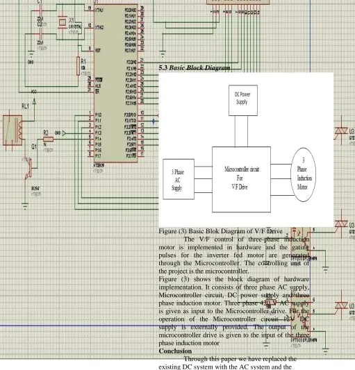
5.3 Basic Block Diagram
Figure (3) Basic Blok Diagram of V/F Drive
The V/F control of three-phase induction motor is implemented in hardware and the gating pulses for the inverter fed motor are generated through the Microcontroller. The controlling unit of the project is the microcontroller.
Figure (3) shows the block diagram of hardware implementation. It consists of three phase AC supply, Microcontroller circuit, DC power supply and three phase induction motor. Three phase 420 V AC supply is given as input to the Microcontroller drive. For the operation of the Microcontroller circuit 12V DC supply is externally provided. The output of the microcontroller drive is given to the input of the three phase induction motor
Conclusion
Through this paper we have replaced the existing DC system with the AC system and the results are as follows:
1. We are able to achieve speed which was also possible with the help of DC system. As we have used induction motor we may improve it further 2. Since we are using V/f control method we can vary voltage and frequency as per requirement of torque and speed.
3. Efficiency can be adjusted with the designed of Induction motor at required torque.
Acknowledgement
I avail this opportunity to express my deep sense of gratitude and sincere thanks to my guide Prof. S.R.Sawalakhe for giving his valuable guidance inspiration and affectionate encouragement to embark this paper.
[image:4.595.78.589.8.541.2]sincere thanks to our principal, Dr. P. M.Jawandhiya who has inspired me a lot to achieve the highest goal. My thanks also goes to Prof. P. R. Jawale, other staff members of Electrical (Electronics & Power) Engineering Department, my parents and my friends who has directly or indirectly involved in making the paper successful.
REFERENCES
[1] Power Electronics: (Convert, Application & Design) Mohan/Undeland/Rossing – John Wiley
[2] Power Electronics: M.D. Singh,
K.B.KhanChandani
[3] B. K. Bose: Modern Power Electronics and
AC Drive, Pearson Education
[4] Electrical machine volume 2 by B.L. Theraja Farzan Rashidi,” Sensorless speed sontrol of induction motor drives using robust and adaptive neuro-fuzzzy basedintelligent controller”,IEEE
[5] International conference on industrial technology (ICIT), 2004, pp. 617-627 [6] Rashidi, F., Rashidi,M.,”Design of robust
sliding mode speed control with fuzzy approach for induction motor”, IEEE international conference onindustrial technology(ICIT03),pp. 27-30.
[7] Mr. Aung Zaw Latt, Dr.Ni Ni Win,”Variable speed drive of single phase induction motor using frequency control method”,International conference on education technology and computer 2009,pp. 30-34
[8] W.I.Ibrahim, R.M.T. Raja Ismail, M.R.Ghazali,”Development of variable speed drive for single phase induction motor based on frequency control”,Proceedings of Encon 2011 4th engineering conference Kuching, Sarawak, Malaysia
[9] H.N.Hickok,” Adjustable speed a tool for saving energy losses in pumps,fan blower and compressors”, IEEE transaction industrial applications,Vol IA21, no.1,PP. 124-136,Jan.1985
[10] M.M.M. Negm,” Torque optimized speed control of a three phase induction motor”,in Proc.Int.Conf.power system technology,power con 2000,pp. 67-72. [11] R.D.Lorendz,”Tuning of field oriented
induction motor controller for high performance applications.
[12] Mrs.Deepali S. Shirke, Prof. Mrs.Haripriya, H.Kulkarni February 2013 “ Microcontroller based speed control of three phase induction
motor using v/f method”, International Journal of Scientific and Research Publications, Volume 3, Issue 2.