Ant-Colony-Based Multiuser Detection for MC DS-CDMA
Systems
Chong Xu, Lie-Liang Yang and Lajos Hanzo
School of ECS., Univ. of Southampton, SO17 1BJ, UK.
Tel: +44-23-80-593 125, Fax: +44-23-80-593 045
Email:
{cx05r, lly, lh}@ecs.soton.ac.uk, http://www-mobile.ecs.soton.ac.uk
Abstract— In this contribution we present a novel ant colony optimiza-tion (ACO) based multi-user detector (MUD) designed for synchronous multi-carrier direct sequence code division multiple access (MC DS-CDMA) systems. The operation of the ACO-based MUD is based on the behaviour of the ant colony in nature. The ACO-based MUD aims for achieving the same bit-error-rate (BER) performance as the optimum maximum likelihood (ML) MUD, without carrying out an exhaustive search of the entire MC DS-CDMA search space constituted by all possible combinations of the received multi-user vectors. We will demonstrate that the system is capable of supporting almost as many users as the number of chips in the spreading sequence, while searching only a small fraction of the entire ML search space. It will also be demonstrated that the number of floating point operations per second is a factor of108lower for the proposed ACO-based MUD than that of the ML MUD, when supportingK= 32users in a MC DS-CDMA system employing31-chip Gold codes as the T-domain spreading sequence.
I. INTRODUCTION
Multi-carrier direct sequence code division multiple access (MC DS-CDMA) is widely recognized as a high-flexibility multiple-access scheme. It is also capable of providing a high degree of freedom for system designers and for channel-adaptive reconfiguration, when compared to both single-carrier DS-CDMA and frequency (F)-domain spread multicarrier CDMA (MC-CDMA) operating without T-domain spreading [1]–[3]. In [4]–[6] the authors have proposed and investigated a MC DS-CDMA system, which employed orthogonal Walsh Hadamad codes as its T-domain spreading sequence, combined with multiple base-station (BS) antenna arrays employed for the sake of achieving either receive diversity [4] in the uplink (UL) or transmit diversity [5], [6] in the downlink (DL). A low-complexity single user detector (SUD) based on a filter matched to the spreading code of the desired user was used in the above contributions. This SUD scheme is optimal in terms of its achievable bit error rate (BER) performance versus the signal-to-noise ratio (SNR), as a benefit of the spreading codes’s orthogonality in the T-domain. However, the orthogonality of the spreading codes is often destroyed by the dispersive channel.
As a design alternative, in this paper, non-orthogonal codes are employed, resulting in multi user interference (MUI), which requires the employment of multi user detection (MUD) [3], [7]. The optimal maximum likelihood (ML) MUD carries out an exhaustive search for all the legitimate combinations of the transmit symbols of all the users. Natrually, this technique has a complexity that increases exponentially with the number of users, as well as with the number of bits per symbol, which motivates the development of reduced-complexity near-optimal MUDs. For instance, genetic algorithms (GA) [3], [8]–[10], evolutionary programming [11], particle swarm optimization [12], ant-colony optimization (ACO) [13]–[15], sphere decoding [16], [17] and Markov-Chain Monte-Carlo (MCMC) [18] aided detectors have found favour in low-complexity near-optimum MUDs.
Acknowledgements: The financial support of the EPSRC, UK and that of the EU under the auspicies of the PHOENIX and NEWCOM projects is gratefully acknowledged.
Data
Serial−to−parallel
converter
Symbol duration
sk(t)
bkU
bk2 ck(t)
cos(2πf11t+φk,11)
cos(2πf12t+φk,12) 1
2 Ts=UTb
bk1
Tb
V
[image:1.595.306.533.185.351.2]UV cos(2πf1Vt+φk,1V)
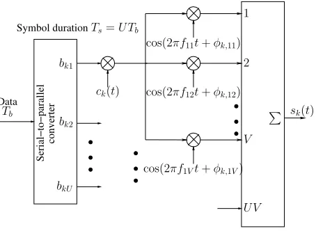
Fig. 1: Thekth user’s uplink transmitter schematic for the generalized multicarrier DS-CDMA system.
In this paper, we present a novel low-complexity ACO based MUD designed for the synchronous MC DS-CDMA uplink. The ACO technique has been shown to outperform GAs in some Non-deterministic Polynomial time (NP)-complete optimization problems, such as the travelling salesman problem [14]. Moreover, according to [19]–[22], the ACO based MUDs are capable of achieving a lower BER and a lower complexity than the GA-based MUDs in wireless communication systems. In this contribution we extend the ACO based single-carrier DS-CDMA system’s MUD of [22] to a multi-carrier DS-CDMA system scenario. The complexity of both the ACO based MUD and that of some traditional detectors designed for MC DS-CDMA are investigated.
The rest of this paper is organized as follows. The MC DS-CDMA system model as well as the matched filter’s (MF) output will be characterized in Section II. In Section III, the ACO algorithm will be detailed. Both the achievable BER performance and the complexity imposed will be quantified in Section IV. Finally, we will conclude our discourse in Section V.
II. SYSTEMDESCRIPTION
A. Transmitter Model
In this subsection, the generalized MC DS-CDMA system of Fig. 1 [2], [23], [24] is reviewed. At the transmitter side, the binary data stream having a bit duration ofTb is Serial-to-Parallel (S/P) converted toU parallel sub-streams. The new bit duration of each sub-stream, which we refer to as the symbol duration, becomes
simultaneously modulates a group ofV parallel subcarrier frequen-cies{fu1, fu2, . . . , fuV}using Binary Phase Shift Keying (BPSK). Thus the transmitted signal on theuvth subcarrier of userkcan be expressed as
sk,uv(t) =
2P
V bku(t)ck(t) cos(2πfuvt+φk,uv), (1)
whereP/V represents the transmitted power of each subcarrier and
P is the transmitted power corresponding to each bit. Furthermore, {bku(t)},{fuv}and{φk,uv}represent the subcarrier data streams, the subcarrier frequency set and the phase angles introduced in the carrier modulation process. A total of U V number of subcarriers are required in the MC DS-CDMA system considered and theU V
number of subcarrier signals are superimposed on each other in order to form the complex-valued modulated signal. Therefore, the transmitted signal of userkcan be expressed as
sk(t) = U
u=1 V
v=1
2P
V bku(t)ck(t) cos(2πfuvt+φk,uv). (2)
B. Receiver Model
We assume thatK synchronous MC DS-CDMA users are sup-ported with the aid of a single receive antenna at the base-station (BS). Furthermore, we assume that the modulated signal of each subcarrier is orthogonal to each other. In this case, we can consider the received signal subcarrier by subcarrier. Thus the (Nc×1) -dimensional received signal vector containing the signals of all the
Kusers associated with theuvth subcarrier can be expressed as
ruv=CHuvξbu+nuv, (3)
where ξ = P/V and C represents the (Nc×K)-dimensional spreading code matrix. Furthermore,Huvis a(K×K)-dimensional matrix, where the diagonal elements of Huv represent the Spatio-Temporal Channel Impulse Responses (ST-CIR) of all the users modulating the uvth subcarrier, which is formulated as Huv = diag (huv,1, huv,2,· · ·, huv,K), wherehuv,kis the complex-valued fading gain of theuvth subcarrier ST-CIR connecting thekth user and the BS. Finally,bu is theK-user transmit signal vector of the
uth bit, which can be expressed as bu= [b1u, b2u,· · ·, bKu]T and
n(nrl)
uv is the(Nc×1)-dimensional additive white Gaussian noise (AWGN) vector, where each element has a zero mean and a variance of2N0. For simplicity, we assume that the ST-CIR are perfect known at the BS. It can be shown that the MRC based MF’s output vector corresponding to the uvth subcarrier of all the K users can be expressed as
yuv= (CHuv)Hruv
=HHuvCTCHuvξbu+HHuvCTnuv
=Ruvξbu+ ˜nuv, (4) where we have
Ruv=HHuvCTCHuv, (5)
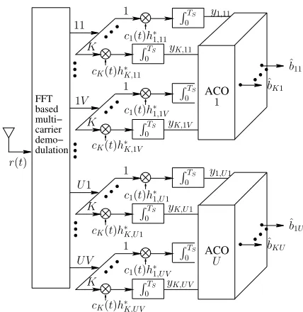
and each element inn˜uvhas a mean of zero and a variance of2N0. As seen in Fig. 2, all theV·Knumber of MF’s outputs{y1,u1, . . . ,
y1,uV, . . . , yK,u1, . . . , yK,uV}related to theuth substream will be input to theuth ACO-based MUD that will generate the(K×1) -dimensional estimate vectorbˆuforbu, which comprises the transmit signals of all theK users mapped to theuth substream.
FFT based multi− carrier demo− dulation
ACO
ACO
TS 0 1
TS 0 yK,U1
K
1
TS 0 yK,UV
K
TS 0 y1,11 1
TS 0 yK,11
K
1
TS 0 yK,1V
K
1V
U1
c1(t)h∗
1,1V
cK(t)h∗K,1V c1(t)h∗
1,11
cK(t)h∗K,11 11
UV
y1,U1
c1(t)h∗
1,U1
cK(t)h∗K,U1
c1(t)h∗
1,UV
cK(t)h∗K,UV
TS 0 TS
0
ˆ
bK1 ˆ
b11
ˆ
bKU ˆ
b1U r(t)
1
[image:2.595.314.528.54.274.2]U
Fig. 2: Uplink receiver block diagram of the generalized MC DS-CDMA system considered for all theK users when employing the maximum likelihood detector or the ACO-based MUD.
III. ANTCOLONYOPTIMIZATIONBASEDMULTIUSERDETECTOR Remembering that the different subcarrier signals are orthogonal, theU number of ACO-based MUDs may operate in parallel without interfering with each other. In each of the U ACO-based MUDs, there is a(2×K)matrix or so-calledroute-table, as shown below,
1 2
1 2
bK= +1
b1= +1
b1=−1
b2= +1
b2=−1 bK=−1
· · · K
· · · · · ·
which represents the two possible choices for the bitsˆbkuof each of theKusers.
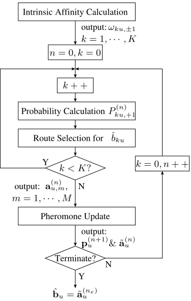
The ACO algorithm [19]–[22] is based on the foraging behavior of the ant colony in nature. Every ant leaves pheromone along the route from the formic nest to a certain remote source of food. Therefore, the shorter the route, the more the pheromone. As a beneficial effect of the pheromone, the ants about to set out from the nest later are more likely to choose the particular route marked by a higher concentration of pheromone. As a result, most ants will choose the shortest route from the nest to the source of food. We assume that there is a total ofNiterations, when searching for the best route in each ACO-based MUD. More specifically, in each of theNiterations,
Route Selection for
Pheromone Update output:
Probability Calculation output:
output:
Y Y
N
N Intrinsic Affinity Calculation
Terminate?
n
= 0
, k
= 0
ˆ
b
kuk < K
?
a
(u,mn),
k
+ +
k
= 0
, n
+ +
P
ku,(n)+1ω
ku,±1p
(un+1)& ˜
a
(un)m
= 1
,
· · ·
, M
k
= 1
,
· · ·
, K
ˆ
[image:3.595.78.266.58.354.2]b
u= ˜
a
(une)Fig. 3: Flow-chart of each of theU ACO-based MUDs.
MUD.
A. Calculation of the Intrinsic Affinity
Let us extend our ant-analogy a little further. In addition to fol-lowing the high-probability routes marked by a high concentration of pheromone, the ants prefer a flat and comfortable route to the source of food. In MUD-parlance, a particular bit of theK-bit vector has a high user-specific LLF value, if it represents a confident bit-decision. In ACO jargon, a high user-specific-LLF-based user-bit corresponds to a less arduous passage of the ants, hence the corresponding bit-value is likely to be confirmed at a high pheromone-level by several of theMants. The flow chart of the instrinsic bit-affinity calculation is shown in Fig. 4.
More quantitatively, let us first of all introduce the so-called desirability function, which can be expressed as [25]:
dku,±1= 1 + exp [−lku(±1)], (6) wherelku(±1)represents the LLF related to thekth user’s bitbku= ±1in the uth substream. In our MC DS-CDMA system, the LLF is given by the superposition of the LLFs associated with all theV
subcarriers {fu1, fu2, . . . , fuV}invoked for transmitting bku. This is formulated as
lku(±1) = V
v=1
lk,uv(±1) (7)
and the user-specific LLF of bku = ±1associated with the uvth subcarrier can be expressed as
lk,uv(±1) =±2
P
V(yk,uv)− P
VRuv,kk, (8)
User−specific LLF User−specific LLF
Y
N
lku(+1) lku(−1)
dku,+1
ηku,+1
ωku,+1
dku,−1
ηku,−1
ωku,−1
k < K?
k+ +
k= 0
[image:3.595.324.516.58.283.2]ωku,±1, k= 1,· · ·, K
Fig. 4: Detailed flow-chart of the ’Intrinsic Affinity Calculation’ block in Fig. 3.
whereRuv,kkrepresents thekth diagonal element ofRuv. Given the desirability function of (6), the sum of its two legitimate values is nomalized according to [22]
ηku,±1=
i∈{+1,−1}dku,i
dku,±1 . (9) Given the normalized desirability function of 9, the intrinsic bit-infinity of thekth user in theuth substream may be expressed as
ωku,±1=ηβku,±1, (10) whereβ is tunable weighting or de-weighting parameter.
B. Probability Calculation and Route Selection
Having completed the intrinsic affinity calculation step of Fig. 3, let us now consider the probability-calculation and route-selection operations of Fig. 3. When considering the two choices of +1 or −1 for user k, M¯ku(n) number of ants will choose +1 and all the other (M−M¯ku(n)) ants will opt for −1. The specific number of ants M¯ku(n) = Γ[M Pku,(n)+1]is based on the probability Pku,(n)+1
calculated by combining the intrinsic affinity of+1or−1and its associated pheromone intensity, while Γ[M Pku,(n)+1] represents the rounded-down integer version of (M Pku,(n)+1). More explicitly, the probability of opting for+1as the esitmated version ofbkuduring thenth iteration can be expressed as [22]
Pku,(n)+1=
µ(ku,n)+1ωku,+1
i∈{+1,−1}µ(ku,in)ωku,i
, (11)
whereµ(ku,n)±1 = [p(ku,n)±1]α represents the effect of the pheromone intensity, whileωku,±1 is the intrinsic affinity introduced in the last subsection. Furthermore, α is a tunable weighting coefficient and
LLF of LLF of
˜ a(n)
u = arg max{Lu[a(u,mn) ], Lu[˜au(n−1)]}, ∀m= 1,· · ·, M a(n)
u,1
Lu[a(u,n1)]
a(n)
u,M Lu[a(u,Mn) ]
[image:4.595.52.294.55.188.2]pu(n+1)=ρpu(n)+PMm=1Lu[au,m(n) ]·A(u,mn) +σLu[˜a(un)]·A˜(un)
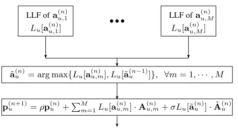
Fig. 5: Detailed flow-chart of the ’Pheromone Update’ block in Fig. 3.
C. Pheromone Update
Let us now continue by considering the pheromone update block of Fig. 3. As observed in the foraging behavior of the ants in nature, every ant in the ACO-aided MUD will leave a certain amount of pheromone along the route it follows. The more ants pursue a particular route, the more pheromone will be assigned to the route. Analogously to the ants in nature which use the distance as their route-quality criterion, the quality of the route in our algorithm is quantified in terms of its LLF.
Based on our above discussions, the amount of pheromone as-signed to each bit constituting a specific route is set to the LLF of the route. The corresponding flow chart of the pheromone update procedure is outlined in Fig. 5. More explicitly, the amount of pheromone assigned to a particular route pursued by the mth ant during thenth iteration is formulated as
∆p(u,mn) =Lu[au,m(n)]·A(u,mn), (12) where a(u,mn) represents the specific K-user vector produced by the
mth ant during thenth iteration and Lu[a(u,m]n) represents the LLF related to theK-user vectorbu=a(u,mn) in theuth substream, while
A(u,mn) is the (2×K)-dimensional matrix representation ofa(u,mn). For instance, if we have a 4-user vector produced by themth ant given bya(u,mn) = [+1,−1,+1,+1]T, we arrive at
A(n) u,m=
1 0 1 1 0 1 0 0
. (13)
Furthermore, an extra amount of pheromone quantified byσ·Lu[˜a(un)] is assigned to a route leading to the most likely K-user vector ˜
a(n)
u found so far, where σ represents the weighting factor of the pheromone assigned to a meritoriousK-user vector. However, there is also a so-called evaporation rate [19]–[22]ρ, allowing the previously assigned pheromone to evaporate, hence creating chances for the ants to find new routes during the next cycle that may be more meritorious than the best route found so far. Finally, the pheromone matrix generated for the(n+ 1)st iteration can be obtained by [22]
p(n+1)
u =ρp(un)+ M
m=1
∆p(u,mn) +σLu[˜au(n)]·A˜(un), (14)
whereLu[˜a(un)]represents the LLF related to theK-user vectorbu= ˜
a(un) in theuth substream.
In our MC DS-CDMA system, the calculation of the LLF value formulated in (12) and (14) and related to the K-user vector bu being a specific vector ˙bi ∈ BK, where BK contains all the 2K possible combinations for the K-user transmit vector, is given by the superposition of the LLFs associated with all the V subcarriers
{fu1, fu2, . . . , fuV}invoked for transmittingbu. This is formulated as
Lu(˙bi) = V
v=1
Luv(˙bi), ˙bi∈ BK, (15)
and the LLF ofbu= ˙biassociated with theuvth subcarrier can be expressed as
Luv(˙bi) = 2
P V(˙b
T
iyuv)−P
V ˙b
T
iRuv˙bi, (16)
i= 1,2, . . . ,2K.
D. Termination Condition
The optimization procedure of theuth ACO-based MUD designed for finding the near-MLK-bit vectorbˆu will terminate at theneth iteration, if either all the ants produce the same K-user vector estimate during the neth cycle, or all theN number of affordable ACO iterations have been carried out, i.e. we havene =N. Then the MUD’s outputbˆu is given by
ˆ
bu= ˜a(une). (17)
Let us now consider both the achievable BER performance and the complexity imposed, when carefully selecting the algorithm’s parameters in the next section.
IV. SIMULATIONRESULT
In this section both the attainable BER performance and the com-plexity of the uplink MC DS-CDMA system using the ACO-based MUD is investigated, when assuming that each subcarrier signal experiences flat Rayleigh fading. In our simulations we assumed that the number of subcarriers varies fromV = 1toV = 128and that the T-domain spreading sequences were theNc= 31-chip Gold codes. The BER performance and the complexity of the proposed ACO-based MUD employed in the MC DS-CDMA UL is also compared to that of the MRC-based correlation detector and to that of the ML MUD detailed in Section II.
Throughout our simulations, the initial pheromone level of
p(1)ku,±1= 0.01was used for all theuth,u= 1. . . U, bit of thekth,
k= 1. . . K user in conjunction withρ= 0.5,M = 10,N = 10,
α= 1,β= 6andσ= 8.
Fig. 6 shows the BER performance versus signal-to-noise ratio (SNR) performance of the MRC-based correlation detector, the ML MUD and the ACO-based MUD, which was introduced in Sec-tions II and III. Again, the number of subcarriers was varied for
V = 1, . . . ,128. Both the uplink MC DS-CDMA system employing the MRC-based correlation detector and the ACO-based MUD are capable of supporting K = 32 users, which is on the order of
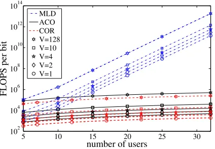
O(232). By contrast, the MC DS-CDMA system employing the ML MUD has an excessive complexity forK= 32users. Fig. 7 shows the complexity versus the number of users at SNR= 10dB for the MRC-based correlation detector, for the ML MUD and the ACO-based MUD along with a different number of subcarriers varing from
V = 1, . . . ,128.
0 5 10 15 20 25 30 10−4
10−3 10−2 10−1 100
10−5
10−6
SNR
BER
Ray Gau COR ACO MLD
V=1
V=2
V=4 V=10
[image:5.595.65.273.62.208.2]V=128
Fig. 6: BER versus SNR performance of the uplink MC DS-CDMA system considered usingV = 1,2,4,10,128subcarriers and Nc= 31-chip Gold codes for T-domain spreading. Both the ACO-based MUD and the correlation detector supportK= 32users, while the ML MUD has an excessive complexity.
5 10 15 20 25 30
1010
102 104 106 108 1012 1014
number of users
FLOPS per bit
MLD ACO COR V=128 V=10 V=4 V=2 V=1
Fig. 7: Complexity per user per bit versus the number of users supported in the uplink of the MC DS-CDMA system considered usingV = 1,2,4,10,128subcarriers andNc= 31-chip Gold codes for T-domain spreading.
V. CONCLUSION
We have investigated an ACO-based MUD designed for the uplink of an MC DS-CDMA system. Our simulation results show that regardless of the number of subcarriers, the ACO-based MUD approaches the BER performance of that of the ML MUD in the proposed MC DS-CDMA system supporting K = 32 users with the aid of length-31 Gold codes used as the T-domain spreading sequences. Our simulation results also show that the proposed ACO-based MUD employed in the MC DS-CDMA system considered is capable of supporting the same number of users at the number of chips in the Gold code in the vicinity of the ML MUD’s BER performance at a complexity, which is similar to that of the MF detector.
REFERENCES
[1] L.-L. Yang and L. Hanzo, “Multicarrier DS-CDMA: A multiple-access scheme for ubiquitous broadband wireless communications,”IEEE Com-munications Magazine, vol. 41, no. 10, pp. 116–124, October 2003.
[2] L.-L. Yang and L. Hanzo, “Performance of generalized multicarrier DS-CDMA over Nakagami-mfading channels,”IEEE Transactions on Communications, vol. 50, pp. 956 – 966, June 2002.
[3] L. Hanzo, L.-L. Yang, E.-L. Kuan and K. Yen,Single- and Multi-Carrier DS-CDMA Multi-User Detection, Space-Time Spreading, Synchronisa-tion and Standards. Chichester, UK: John Wiley and Sons, Ltd, 2003. [4] B. Hu, L.-L. Yang and L. Hanzo, “Performance of the smart antenna aided multicarrier DS-CDMA uplink,” inIEEE 60th Vehicular Technol-ogy Conference. IEEE, September 2004, pp. 191 – 195.
[5] B. Hu, L.-L. Yang and L. Hanzo, “Performance of the smart antenna aided generalized multicarrier DS-CDMA downlink using both time-domain spreading and steered space-time spreading,”IEEE 62nd Ve-hicular Technology Conference,, vol. 1, no. 28-25, pp. 458–462, Sept. 2005.
[6] C. Xu, B. Hu, L.-L. Yang and L. Hanzo, “Performance of multi-antenna array assisted MC DS-CDMA using downlink preprocessing based on singular value decomposition,” in Proceedings of IEEE Vehcular Technology Conference, 2007, pp. 1936–1940.
[7] S. Verdu,Multiuser Detection. Cambridge University Press, 1998. [8] T.-C. Fogarty, “Using the genetic algorithm to adapt intelligent systems,”
IEE Colloquium on symbols versus Neurons, vol. 12, pp. 4/1–4/4, October 1990.
[9] Y. Kai and L. Hanzo, “Genetic algorithm assisted joint multiuser symbol detection and fading channel estimation for synchronous CDMA systems,”IEEE Journal on Selected Areas in Communications, Vol. 19, pp. 985–998, June 2001.
[10] M. Jiang, S.-X. Ng and L. Hanzo, “Hybrid iterative multiuser detection for channel coded space division multiple access OFDM systems,”IEEE Transactions on Vehicular Technology, vol. 55, pp. 115–127, Jan. 2006. [11] D. Fogel, “What is evolutionary computation?,”IEEE Spectrum, vol. 37,
pp. 28–32, Feburary 2000.
[12] J. Kennedy and R. Eberhart, “Particle swarm optimization,” IEEE International Conference on Neural Networks, vol. 4, pp.1942–1948, December 1995.
[13] M. Dorigo, L. Gambardella, M. Middendorf and T. Stutzle, “Guest editorial: special section on any colony optimization,”IEEE Transactions on Evolutionary Computation, vol. 6, pp.317–319, August 2002. [14] M. Dorigo and L. Gambardella, “Ant colony system: a cooperative
learn-ing approach to the travelllearn-ing salesman problem,”IEEE Transactions on Evolutionary Computation, vol. 1, pp.53–66, April 1997.
[15] M. Dorigo and G. Di Caro, “Ant colony optimization: a new meta-heuristic,”Proceedings of the 1999 Congress on Evolutionary Compu-tation, vol. 2, pp.1470–1477, July 1999.
[16] L. Hanzo and T. Keller,OFDM and MC-CDMA: A Primer. Chichester, UK: John Wiley and Sons, Ltd, 2006.
[17] J. Boutrous and E. Viterbo, “Signal space diversity: A power and bandwidth efficient diversity technique for the Rayleigh fading channel,”
IEEE Transactions on Information Theory, vol. 44, pp.1453–1467, Jul. 1998.
[18] Z.-G. Yang, B. Lu and X.-D. Wang, “Bayesian Monte Carlo multiuser receiver for space-time coded multicarrier CDMA systems,”IEEE Jour-nal on Selected Areas in Communications, vol. 19, pp.1625–1637, Aug. 2001.
[19] S.L. Hijazi, A.J. Best B. Natarajan and S. Das, “Ant-colony based optimal MC-CDMA multiuser detector,”IEEE International Conference on Wireless And Mobile Computing, Networking And Communications, vol. 1, pp.128–132, August 2005.
[20] S.L. Hijazi, B. Natarajan and S. Das, “An ant-colony algorithm for multi-user detection in wireless communication systems,”Genetic and Evolutionary Computation Conference, pp.2121–2126, June 2005. [21] S.L. Hijazi and B. Natarajan, “Novel low-complexity DS-CDMA
mul-tiuser detector based on ant colony optimization,” IEEE Vehicular Technology Conference, vol. 3, pp.1939–1943, September 2004. [22] J.-J. Lai and J.-K. Lain, “Antenna-diversity-assisted ant-colony-based
multiuser detection for DS-CDMA systems,”IEEE International Work-shop on Cellular Neural Networks and Their Applications, vol. 3, pp.106–109, May 2005.
[23] L.-L. Yang and L. Hanzo, “Performance of generalized multicarrier DS-CDMA over using various chip waveforms,”IEEE Transactions on Communications, vol. 51, pp. 748–752, May 2003.
[24] L.-L. Yang and L. Hanzo, “A unified approach to the analysis of multi-carrier DS-CDMA over Nakagami-mfading channels,” inProceedings of IEEE GLOBECOM, (San Antonio, Texas, USA), November 25-29, 2001.
[image:5.595.59.271.299.446.2]