Modelling and Control of Direct Drive Variable Speed
Wind Turbine with Interior Permanent Magnet
Synchronous Generator
Mujaddid Morshed Chowdhury B.Sc. Engg., (Electrical and Electronic)
A thesis submitted in fulfillment of the requirements for the degree Of
Doctor of Philosophy
University of Tasmania
ii
Declaration and Statements
Declaration of Originality
"This thesis contains no material which has been accepted for a degree or diploma by the University or any other institution, except by way of background information and duly acknowledged in the thesis, and to the best of my knowledge and belief no material previously published or written by another person except where due acknowledgement is made in the text of the thesis, nor does the thesis contain any material that infringes copyright.”
Authority of Access
This thesis may be made available for loan and limited copying and communication in accordance with the Copyright Act 1968.
Statement regarding published work contained in thesis
“The publishers of the papers comprising Chapter 3 and Chapter 5 hold the copyright for that content, and access to the material should be sought from the respective journals. The remaining non published content of the thesis may be made available for loan and limited copying and communication in accordance with the Copyright Act 1968.”
iii
Acknowledgement
First of all, I would like to thank Almighty Allah to enable me to complete my PhD research.
I would like to express my sincere gratitude and appreciation to my primary supervisor Dr. M. E. Haque for his guidance, support and encouragement throughout my PhD studies. I am also grateful to my co-supervisors for their comments and support on my research works.
I enjoyed the friendly working environment at the School of Engineering & ICT. I would like to thank the laboratory staff for their support. Special thanks to Mr. James Lamont for his support in experimental works in the power lab.
I would like to thank the School of Graduate Research and University of Tasmania for providing me with a scholarship and support during my PhD studies.
I would like to thank my daughter Ashfia, and sons Maheeb and Mihran for their love, patience and the time they spent without me during the research works.
iv
Abstract
v
The parameters of IPM synchronous generators have an important influence on the steady state and dynamic performance analysis of the variable speed wind turbine. The knowledge of the machine model and accurate parameters is mandatory to analyze the performance and to design efficient and fast controllers for the variable speed wind turbine. Therefore, accurate measurement of these parameters is essential. This thesis presents simple practical methods of determining parameters such as magnet flux, and,
d- and q-axes inductances of an IPM synchronous generator. An experimental test set-up is developed and the results are presented.
The second contribution of the thesis is to develop an improved indirect vector control scheme for the IPM synchronous generator based direct drive variable speed wind turbine, incorporating maximum torque per ampere trajectory (MTPA) and a maximum power extraction (MPE) algorithm. The main advantage of incorporating MTPA trajectory in the control scheme is that it can generate the required torque with a minimum stator current. Therefore, the stator loss of the IPM synchronous generator is minimized. The proposed control scheme is simulated in Matlab/SimPowerSystems
environment and experimentally implemented using a DSpace DS1104 digital signal processor (DSP) system. The simulation and experimental results confirm the effectiveness of the developed control scheme to control the direct drive variable speed wind turbine with MPE under varying wind speed.
vi
vii
Contents
Declaration and Statements (ii)
Acknowledgement (iii)
Abstract (iv)
Content (vii)
List of figures (xiv)
List of tables (xx)
List of symbols (xxi)
Abbreviations and acronyms (xxiii)
Chapter 1 Introduction
11.1 Background 1
1.2 Recent Trends in Wind Turbine Technologies and Control 3
1.2.1 Wind turbine technologies 4
1.2.1.1 Fixed speed wind turbine technology 4
1.2.1.2 DFIG based gear-driven variable speed wind turbine technology
4
1.2.1.3 PMSG based gearless direct drive variable speed wind turbine with full scale converter
5
1.3 Problem Statement and Motivation for the Current Research 7
1.4 Contributions of this Research 10
1.5 Thesis Outline 11
1.6 List of Publications 13
Chapter 2 Modelling of Wind Turbine and Wind Energy System
Configurations
15
viii
2.2 Wind source and characteristics 15
2.3 Modelling of wind turbine 17
2.3.1 Power in the wind 17
2.3.2 Power captured by the wind turbine 18
2.3.3 Optimum power extraction from a variable speed wind turbine
20
2.3.4 Stream tube model of air flow for theoretical maximum power extraction
22
2.4 Influence of the Number of Turbine Blades on the Rotor Power Coefficient
26
2.5 Horizontal Axis and Vertical Axis Wind Turbine 28
2.5.1 Horizontal Axis Wind Turbine (HAWT)
28 2.5.2 Vertical Axis Wind Turbine (VAWT)
29
2.6 Onshore and Offshore Wind Turbine 30
2.6.1 Onshore Wind Turbine 30
2.6.2 Offshore Wind Turbine
31
2.7 Wind Turbine Aerodynamics 31
2.7.1 Wind Turbine Power Characteristics 31
2.7.2 Aerodynamic Power Control of Wind Turbine 33
2.7.2.1 Passive Stall Control 35
2.7.2.2 Active Stall Control 35
2.7.2.3 Pitch Control 36
2.7.2.4 Pitch Control vs. Stall Control 38
2.8 Wind Energy System Configurations 39
2.8.1 Fixed Speed Wind Turbine
39 2.8.2 Variable Speed Wind Turbine
42
ix
Chapter 3 Analysis, Modelling and Parameter Estimation of
Permanent Magnet Synchronous Generator
47
3.1 Overview 47
3.2 Generators for Wind Turbine Applications 49
3.3 Permanent Magnet Synchronous Generator for Variable Speed Wind Turbine
50
3.3.1 Rotor Configurations of PMSGs 51
3.4 Mathematical Representation of Permanent Magnet Synchronous Generator in Machine Variables
53
3.4.1 Inductance and Flux linkage in a PMSG 54
3.4.2 Voltage and Torque Equations in Machine variables 56 3.4.3 d-q Modelling of Permanent Magnet Synchronous 57 3.4.4 Phasor Diagram and Power Angle Characteristics of
Permanent Magnet Synchronous Generator
60
3.4.4.1 Power Angle Characteristics of a Non-salient Pole PMSG
60
3.4.4.2 Power Angle Characteristics of a Salient Pole PMSG 64 3.5 Parameter Measurement of IPM Synchronous Generator 66
3.5.1 Armature Resistance (Ra) Measurement 67
3.5.2 Determination of Magnet Flux Linkage (M) 67
3.5.3 Measurement of d-axis Inductance (Ld) and q-axis Inductance (Lq)
69
3.5.4 Measurement of d-axis Inductance (Ld) and q-axis Inductance (Lq) for Machine with Accessible Neutral Point
70 3.5.5 Measurement of d-axis Inductance (Ld) and q-axis
Inductance (Lq) for Machine with Inaccessible Neutral Point
71
3.5.6 Experimental Setup 75
3.6 Summary 77
x
Chapter 4
Control
of
Permanent
Magnet
Synchronous
Generator Based Direct Drive Variable Speed Wind
turbine
79
4.1 Overview 79
4.2 Review of Control Strategies for Direct Drive Variable Speed Wind Turbine with PMSG
80
4.3 Indirect Control Strategies for Generator Side Converter of PMSG Based Direct Drive Variable Speed Wind Turbine
82
4.4 Modelling, Analysis and Control of PMSG Based Variable Speed Wind Turbine with Switch-mode Rectifier
82
4.4.1 System Structure 82
4.4.2 Three Phase Diode Rectifier 84
4.4.3 Design of Boost DC-DC Converter 86
4.4.4 Control of Boost DC-DC Converter with Maximum Power Extraction
87
4.4.5 Simulation Model 88
4.4.6 Simulation Results and Discussions 88
4.5 Control of PMSG Based Direct Drive Variable Speed Wind Turbine with Back to Back PWM Converter
92
4.5.1 System Structure 92
4.5.2 Analysis of PWM Rectifier 93
4.5.3 Control of Generator Side PWM Rectifier with Maximum Power Extraction
96
4.5.3.1 The Proposed Maximum Power Extraction Algorithm 96 4.5.3.2 Control of PMSG with Maximum Torque Per Ampere
(MTPA) Control
98
4.5.3.3 Simulation Model 102
xi
4.6 Control of Inverter in Grid Connected Mode 112
4.6.1 Vector Control of Grid Side Inverter with Decoupled Current Controller
112
4.6.1.2 Detection of Grid Voltage Angle 113
4.6.1.3 Vector Control in dq- synchronous Reference Frame 114
4.6.1.4 Simulation Results and Discussions 119
4.7 Control of Inverter in Stand-Alone Mode 124
4.7.1 Simulation Results and Discussions 125
4.8 Experimental Results 129
4.9 Summary 133
Chapter 5
Direct Control Scheme of IPM Synchronous
Generator Based Direct Drive Variable Speed Wind
Turbine
135
5.1 Overview 135
5.2 The Proposed Direct Control Scheme for IPM Synchronous Generator Based Variable Speed Wind Turbine
137
5.2.1 The concept of direct torque and flux control of IPM synchronous generator
137
5.2.2 Analysis of Direct Torque and Flux Control Scheme of IPM Synchronous Generator
138
5.2.2.1 Control of Stator Flux Linkage by Selecting Proper Stator Voltage Vector
140
5.2.2.2Control of Amplitude of Stator Flux Linkage
142
5.2.2.3Control of Rotation of s 142
5.3 Implementation of DTFC Scheme for IPM Synchronous Generator Based Variable Speed Wind Turbine
144
5.4 Control of Grid Side Voltage Source Inverter with Decoupled Vector Control Scheme
xii
5.5 Results and Discussions 146
5.5.1 Performance of the Generator Side Direct Torque and Flux Controller
147
5.5.2 Performance of the Decoupled Vector Control Scheme of the Grid Side Inverter
150
5.6 Summary 152
Chapter 6
Dynamic Performance Enhancement of a Grid
Connected Wind Farm with STATCOM and
Supercapacitor Energy Storage
153
6.1 Overview 153
6.2 Issues and Impacts of Wind Energy Integration into the Grid 154
6.3 Grid Code and Interconnection Requirements 155
6.3.1 Low Voltage Ride Through or Fault Ride Through Capability of Wind Turbines
155
6.3.2 Active Power Control 157
6.3.3 Reactive Power Control 157
6.4 Supercapacitor Energy Storage 159
6.4.1 Construction and Features of Supercapacitor 160
6.4.2 Supercapacitor Model 163
6.5 Reactive Power Compensation Techniques 164
6.5.1 Static Var Compensator (SVC) 165
6.5.2 Static Synchronous Compensator (STATCOM) 167
6.6 STATCOM Operation and Control Modes 168
6.6.1 Reactive Power Control 169
6.6.2 Voltage Magnitude Control at PCC 169
6.6.3 Power Factor Control at PCC 170
xiii
6.8 Simulation Results and Discussions 174
6.8.1 System Structure 174
6.8.2 Performance Evaluation of STATCOM with Supercapacitor Energy Storage Under Different Contingencies
175
6.8.2.1 Performance of the STATCOM during voltage swell and voltage sag
175
6.8.2.2 Performance of the STATCOM during three phase fault
176
6.8.2.3 Performance of the STATCOM during sudden load changes
177
6.8.2.4 Performance of the STATCOM Controllers under different contingencies
178
6.8.2.5 Performance Comparison of the STATCOM with Supercapacitor Energy Storage and SVC
179
6.9 Summary 180
Chapter 7
Conclusions and Suggestions for Future Research
1817.1 Conclusions 181
7.2 Suggestion for Future Research 184
xiv
List of Figures
Figure 1.1 Global wind power capacity (2000-2013)
Figure 1.2 Fixed speed wind turbine with induction generator Figure 1.3 Gear-driven variable speed wind turbines
Figure 1.4 Gearless Direct drive variable speed wind turbine PMSG or Multi-pole synchronous generator
Figure 2.1 Typical wind speed and wind power characteristics Figure 2.2 Air mass m flowing through an area A with a velocity vw
Figure 2.3 Power in the wind, per square meter of cross section, at 150C and 1 atm Figure 2.4 Power coefficients versus tip speed ratio
Figure 2.5 Mechanical power generated by turbine as a function of the rotor speed for different wind speed
Figure 2.6 Approaching wind slows and expands as a portion of its kinetic energy is extracted by the wind turbine, forming the stream tube shown
Figure 2.7 Ideal power coefficient verses vw2/vw1
Figure 2.8 Stream tube model including the rotating wake behind a turbine like energy converter
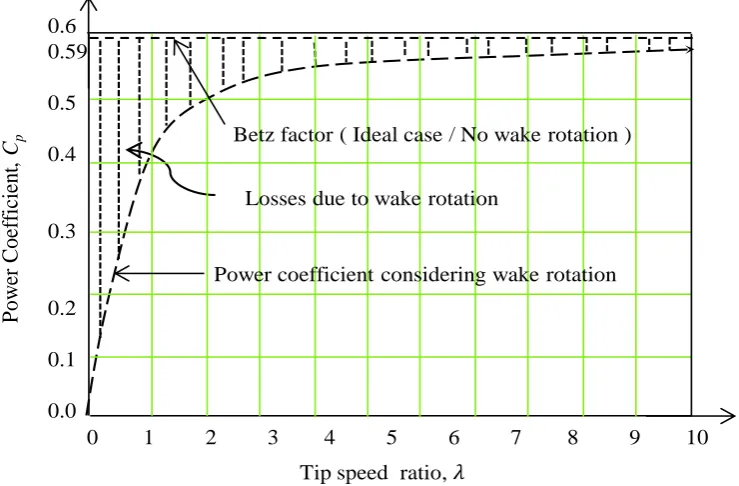
Figure 2.9 Betz factor, rotor real power coefficient considering wake rotation and losses due to wake rotation
Figure 2.10 Influence of the number of turbine blades on the rotor power coefficient Figure 2.11 (a) One blade wind turbine (b) Two blades wind turbine (c) Three blades
wind turbine
Figure 2.12 Horizontal axis wind turbine (a) upwind turbine (b) downwind turbine Figure 2.13 Vertical axis wind turbine. (a) Musgrove wind turbine (b) Derries wind
turbine
Figure 2.14 Performance characteristics of HAWT and VAWT Figure 2.15 Onshore wind farm
xv
Figure 2.17 Wind turbine power curve in different region Figure 2.18 Wind Turbine components
Figure 2.19 Turbine blade aerodynamic and angle of attack Figure 2.20 Passive stall control
Figure 2.21 Active stall control Figure 2.22 Pitch control
Figure 2.23 Power characteristics of a wind turbine during stall, active and pitch control
Figure 2.24 Different generators for wind energy conversion system
Figure 2.25 System operating point and maximum power points at different wind speeds
Figure 2.26 Squirrel cage induction generator based fixed speed wind turbine Figure 2.27 PMSG or Multi-pole synchronous generator
Figure 2.28 Indirect drive variable speed wind turbines with gearbox Figure 3.1 Classification of widely used wind turbine Generators Figure 3.2 Orientation of permanent magnet materials in PMGs
Figure 3.3 Magnetic flux paths of a salient pole PM synchronous machine Figure 3.4 (a) Three phase, two pole PMSG (b) Equivalent circuit of PMSG Figure 3.5 Three phase to d-q transformation
Figure 3.6 d-q model of PMSG in synchronous reference frame Figure 3.7 Per phase equivalent circuit diagram of a PMSG Figure 3.8 Phasor diagram of PMSG
Figure 3.9 Power angle characteristics of a non-salient pole permanent magnet synchronous machine
Figure 3.10 Phasor diagrams of a salient pole permanent magnet synchronous generator
xvi
Figure 3.13 Back emf of the IPM synchronous generator at 734 rpm
Figure 3.14 IPM synchronous generator open circuit line to line voltage vs generator speed
Figure 3.15 Circuit connection diagram for d- and q-axis inductance measurement (with neutral connection available)
Figure 3.16 Circuit connection diagram for d- and q-axis inductance measurement (without access to neutral point )
Figure 3.17 Generator voltage and current waveforms at different generator currents Figure 3.18 Measured self-inductance of IPM synchronous generator
Figure 3.19 Measured d- and q-axis inductances vs. generator current Figure 3.20 Experimental test set up for the parameter measurement
Figure 4.1 PMSG based variable speed wind Turbine with diode rectifier and boost DC-DC converter
Figure 4.2 PMSG with three phase diode rectifier
Figure 4.3 PMSG with three phase diode rectifier with generator inductance Ls
Figure 4.4 Boost DC-DC converter
Figure 4.5 Proposed maximum power extraction algorithm under varying wind speed
Figure 4.6 Performance of generator side switch-mode converter controller with maximum power extraction
Figure 4.7 Performance of generator side switch-mode converter controller with maximum power extraction (Expanded view)
Figure 4.8 Generator power vs turbine speed
Figure 4.9 Generator torque, voltage and current responses at the rated operating conditions
Figure 4.10 PMSG based variable speed wind Turbine with back to back PWM converters
Figure 4.11 PWM rectifier circuit connected to the PMSG
xvii
Figure 4.14 Phasor diagram of the PWM rectifier at unity power factor
Figure 4.15 Control of Generator side converter with MTPA and maximum power extraction
Figure 4.16 Mechanical turbine power vs wind speeds
Figure 4.17 Space vector diagram of IPM synchronous generator with maximum torque per ampere control
Figure 4.18 Trajectory of stator current at Tg = 0.8 pu
Figure 4.19 Trajectory of maximum torque per ampere control
Figure 4.20 Performance of MTPA controller for generator side PWM rectifier with maximum power extraction under varying wind speed
Figure 4.21 Performance of MTPA controller for generator side PWM rectifier with maximum power extraction under varying wind speed. (Expanded view)
Figure 4.22 Generator electromagnetic torque, turbine mechanical torque and generator power responses under varying wind speed
Figure 4.23 Generator voltage, current and torque responses at rated operating condition
Figure 4.24 Locus of generator stator current vector under MTPA control
Figure 4.25 Transient responses of generate speed, generate power, turbine torque and generator torque when wind speed increased to rated value at t = 4 sec
Figure 4.26 Comparison of torque responses under vector control with PWM rectifier and switch-mode rectifier
Figure 4.27 Maximum power extraction under varying wind speed (mechanical power vs generator speed)
Figure 4.28 Comparison of Maximum power extraction under two control methods Figure 4.29 PMSG based variable speed wind Turbine with back to back PWM
converters
Figure 4.30 Vector control of grid side inverter with decoupled current controllers Figure 4.31 Stationery abc frame to rotating synchronous reference frame
transformation
xviii
Figure 4.33 DC link voltage, current and power responses in grid connected mode Figure 4.34 Grid voltage, current, frequency, active power and reactive power
responses in grid connected mode
Figure 4.35 Instantaneous grid voltage and current at rated condition Figure 4.36 Control of load side inverter in stand-alone mode
Figure 4.37 Performance of the load side inverter controller in stand-alone mode Figure 4.38 Load voltage, current, active power, reactive power responses in
stand-alone mode
Figure 4.39 Instantaneous load voltage and current in stand-alone mode Figure 4.40 Inverter output rms voltage, frequency and modulation index Figure 4.41 Experimental Set up
Figure 4.42 Performance of the DSP based vector controller for a wind speed variation of 7 m/s-8m/s-9 m/s-10 m/s- 9 m/s- 8 m/s
Figure 4.43 Maximum power extraction under varying wind speed (Experimental Results)
Figure 4.44 Inverter output voltage and current at rated load
Figure 5.1 Proposed DTFC scheme of IPM synchronous generator Figure 5.2 The stator and rotor flux linkages in different reference frames
Figure 5.3 A rectifier connected to IPM synchronous generator and switching modes
Figure 5.4 Available stator voltage vectors
Figure 5.5 The control of the amplitude of stator flux linkage
Figure 5.6 Control of grid side voltage source inverter with decoupled vector control scheme
Figure 5.7 The performance of DTFC scheme of IPM synchronous generator based variable speed wind turbine under varying wind speed
Figure 5.8 Locus of the stator flux linkage of IPM synchronous generator
xix
Figure 5.10 Performance of the grid side decoupled vector controller for the voltage source inverter under varying wind speeds
Figure 5.11 Grid voltage, current, active power, reactive power and frequency responses under varying wind speed
Figure 6.1 Fault ride through requirement for some countries Figure 6.2 Fault ride through requirement for Australia
Figure 6.3 Danish TSO’s reactive power demand for wind power plants during normal operation.
Figure 6.4 German TSO’s reactive power demand for wind power plants as function of the voltage at nominal active power
Figure 6.5 German TSO’s reactive power requirement for wind power plants plant as function of the active power when the WPP is working at de-rated power.
Figure 6.6 Construction of a supercapacitor Figure 6.7 Supercapacitor model
Figure 6.8 Static VAR Compensator (SVC) and its V-I characteristic Figure 6.9 STATCOM and its V-I characteristic
Figure 6.10 STATCOM equivalent circuit
Figure 6.11 Reactive power of STATCOM for leading and lagging power factor Figure 6.12 Three level NPC based STATCOM connected to the grid
Figure 6.13 Single phase equivalent circuit of the STATCOM system
Figure 6.14 Control scheme of STATCOM with decoupled current controllers Figure 6.15 System configuration of the studied system
Figure 6.16 Performance of STATCOM during voltage swell and voltage sag
Figure 6.17 Performance of STATCOM during three, two and single phase short circuit
Figure 6.18 Performance of STATCOM during sudden load changes
Figure 6.19 Performance of STATCOM controllers during voltage swell, voltage sag, fault and load changes
xx
List of Tables
Table 2.1 Summary of main features of a fixed speed wind turbine Table 2.2 Summary of main features of variable speed wind turbines
Table 3.1 IPM Synchronous Generator Open Circuit Voltage at Different speeds Table 3.2 d-axis and q-axis inductances at different generator currents
Table 3.3 Parameters of the IPM Synchronous Generator Table 5.1 Switching Table for DTFC
Table 5.2 DQ-axes voltages (VD = 2/3 VDC)
xxi
List of Symbol
µs micro second
A cross-sectional area through which the wind passes
C DC-link Capacitance
CP power coefficient
ia, ib , ic Line output currents of the power inverter
id d-axis current
iq q-axis current
J inertia
LA component of the self-inductance
Laa ,Lbb ,Lcc stator self-inductances
Lab, Lbc, Lca stator to stator mutual inductance
Ld d-axis inductance
Lf line inductance
Ll armature leakage flux
Lmd ,Lmq d- and q- axis magnetizing inductances
Lq q-axis inductance
m air mass
M mutual inductance
ma modulation index
Ns stator windings turns number
p the operator d/dt
PG real power
PG1 excitation power
PG2 reluctance power
xxii
Pwind power in the wind
QG reactive power
R the radius of the turbine
Rf line resistance
Rs stator resistance
S per phase complex power
SGs Synchronous generators
Tg generator electromagnetic torque
Tm turbine mechanical torque
TSR tip-speed to wind speed ratio
vab, vbc , vca Line to line voltages of the power inverter
Vdc DC-link voltage
vw wind speed
vw1 upwind velocity of the undisturbed wind
vw2 downwind velocity
vwT velocity of the wind through the plane of the rotor blades
β pitch angle
δ power angle
θg grid voltage angle
θr rotor position
λ tips speed ratio
λd, λq d- and q- axes stator flux linkages
λM rotor magnet flux
ρ air density
ϕg grid power factor angle
xxiii
Abbreviations
AC Alternative Current
AVR Autonomic Voltage Regulator
DC Direct Current
DFIG Doubly Fed induction generator
DTC Direct Torque Control
DTFC Direct Torque and Flux Control FACTS Flexible AC Transmission System HAWT Horizontal Axis Wind Turbines IGBT Insulated Gate Bipolar Transistor IPM Interior Permanent Magnet
LVRT Low Voltage Ride Through
MPE Maximum Power Extraction
MPP Maximum Power Point
MTPA Maximum Torque Per Ampere trajectory
p:u: per unit value
PCC Point Common Coupling
PF Power Factor
PI Proportional Integral controller
PID Proportional Integral Derivative controller
PLL Phase Locked Loop
PMSG Permanent Magnet Synchronous Generator
PWM Pulse Width Modulation
SC Supercapacitor
SCIG Squirrel Cage Induction Generator SSSC Static Synchronous Series Compensator STATCOM Static Synchronous Compensator
SVC Static Var Compensator
SVM Space Vector Modulation
xxiv UPFC Unified power flow controller VAWT Vertical Axis Wind Turbines
VSC Voltage Source Converter
WPP Wind Power Plant
1
Chapter 1
Introduction
1.1
Background
Recent trend indicates that wind energy will play a major role to meet the future energy target worldwide to reduce reliance on fossil fuel and to minimize the adverse impact of climate change. Wind energy is the fastest growing generation technology among the renewable energy sources. Over the last decade, the global wind energy capacity has increased rapidly and wind is an important competitor to the traditional sources of energy. In 2013, more than 35 GW of wind power capacity was added to the global wind generation capacity which became 318 GW as shown in Fig.1.1 [1]. Since 2008, annual growth rates of cumulative wind power capacity have averaged 21.4%, and global capacity has increased eightfold over the past decade [1], [2]. Recently, capital costs of wind generation technologies have declined primarily due to the competition and advanced technology development including taller towers, longer blades, and smaller generators in low wind speed areas—have increased capacity factors [1]. The technological development contributed to reduce the costs of wind turbines and made it competitive relative to fossil fuel based generation. Onshore wind-generated power is now more cost competitive on a per kWh basis with new coal/gas fired power plants, in several markets (including Australia, Brazil, Chile, Mexico, New Zealand, South Africa, Turkey, much of the EU, and some locations in India and the United States) [1], [2]. As a result of this trend, high level of wind energy (>30%) will be integrated into the power
grid and major challenges and issues will appear, which are needed to be addressed for
efficient and reliable operation of the existing power system.
2
(a) Global wind power capacity (2000-2013)
[image:26.595.56.503.87.354.2](b) Global wind power capacity and addition, Top 10 countries.
3
challenges in; grid interconnections and bi-directional power control, tight voltage and frequency regulation, dynamic stability, low voltage fault ride through, satisfy grid code, system security, reliability, and protection [3].
Therefore, a better understanding of the technology involved with the grid integration of the variable speed wind turbines and possible impacts of large scale wind integration to the power grid is mandatory to ensure reliable and secure operation of the power system.
1.2 Recent Trends in Wind Turbine Technologies and Control
Over the last two decades, wind power has become the most promising renewable energy technology due the development in wind turbine aerodynamics, structure, variable speed generator technologies, power electronics and DSP (digital signal processor) based control topologies. The wind turbine industries is continuously moving forward in order to increase efficiency and controllability of the variable speed wind turbines to enhance the large scale grid integration of wind energy conversion system. Recent trend indicates an increase in large scale wind farms, which will contribute to significant share of the energy. They will also introduce new challenges and issues in the power system operation and control. These challenges include integration to the weaker grid, voltage and frequency regulation, dynamic voltage stability under disturbances, power fluctuations and changing dynamics of the conventional power plants [3], [4]. The wind farms will have to fulfil the new grid code requirement for reliable and stable operation of the power system. Currently, the doubly fed induction generator (DFIG) based gear-driven variable speed wind turbine technology dominating the market. However, there is an increasing trend for permanent magnet synchronous generator (PMSG) based gearless direct drive variable speed wind turbine due to superior performance, efficiency, smaller size, less maintenance and enhanced fault ride through capability [3].
4
1.2.1 Wind Turbine Technologies
1.2.1.1 Fixed Speed Wind Turbine Technology
Fig.1.2 show the fixed speed wind turbine which uses a squirrel cage induction generator (SCIG) directly connected to the grid through a coupling transformer [3]. A capacitor bank
is required for the compensation of reactive power requirement of induction generator. The problems associated with induction generator based fixed speed wind turbines are reactive power consumption, mechanical stress and poor power quality [4], [5]. In a fixed speed wind turbine, fluctuations in wind speed are transmitted as fluctuations in the mechanical torque, and that results in fluctuations in the electrical power [4]. The power fluctuations can also lead to large voltage fluctuations in a weak grid system [4]. This configuration does not support any speed control, it requires a stiff grid and its mechanical
construction must be able to tolerate high mechanical stress [3].
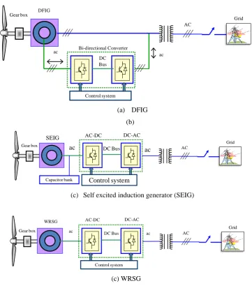
1.2.1.2 DFIG Based Gear-Driven Variable Speed Wind Turbine Technology
Currently, variable-speed wind turbine technologies are very popular because of their advantages such as increased energy capture, maximum power extraction, higher efficiency and better power quality [4]-[6]. Most of the current installed turbines use doubly fed induction generator (DFIG) based variable speed wind turbines with gearbox as shown in Fig.1.3 (a) [7]-[10]. The advantage of this technology is that it requires power converter with reduced capacity (30% of full capacity) as the converter is connected to the rotor circuit instead of stator circuit [4]. In this configuration, the stator is directly connected to the grid and the rotor is connected to grid through a power converter
to control the rotor frequency and the rotor speed [4]. Depending on the size of the
frequency converter (usually rated at approximately 30% of nominal generator power) this
technology can operates in a wide speed range. Typically, the variable speed range is ±30% around the synchronous speed, which makes this concept attractive and popular from
economic point of view [11]. When the generator runs at super-synchronous speed, the
electrical power is injected to the grid through both the rotor and the stator. When the
generator runs at sub-synchronous speed, the electrical power is delivered into the rotor
from the grid [3]. Fig.1.3 (b) and Fig.1.3(c) show self-excited induction generator and
wound rotor synchronous generator based gear driven variable speed wind turbines,
5
However, the main drawback of this type of wind turbine is the requirement of a gearbox which requires regular maintenance and suffers from faults and malfunctions [4]. Moreover, it increases the overall size of the wind turbine. Another disadvantage of DFIG topology is that it is very sensitive to grid disturbance, especially for the voltage dip,
due to the fact that the stator is directly connected to the grid [3]. The voltage dip could
cause over voltage and over current in the rotor windings and consequently damaged the
rotor side converter [3]. To provide a DFIG with good fault ride through (FRT) the wind
turbine and the power converter should have the ability to protect itself, without
disconnecting during faults. In order to fulfill this requirement, a crowbar is needed to offer
extra protection to bypass the converter by short-circuiting the rotor windings [12].
1.2.1.3 PMSG Based Gearless Direct Drive Variable Speed Wind turbine with Full
scale Converter
In this configuration, the generator rotor is directly connected to the turbine rotor without any gearbox and the generator is interfaced with the grid/load using full scale AC-DC-AC power converters as shown in Fig.1.4. This configuration is most suited for full power control as it is connected to the grid through a power converter. The permanent
magnet synchronous generators (PMSGs) used in this configuration are low speed
generators with suitable number of poles and able to produce higher torque at low speed.
The full-scale power converter can perform smooth grid connection over the entire speed
range [3]. The power electronic converters used in this configuration have two primary
goals: to act as an energy buffer (DC-link) for the power fluctuations caused by the wind
turbine and for the transients coming from the grid side and enables the system to control
active and reactive power [3]. The main features of PMSG based wind turbines are [13]-[20]:
o gearless operation and enhanced reliability o simple structure, smaller size and reduced cost o low mechanical and electrical losses
o higher power factor and efficiency
6
[image:30.595.88.450.333.747.2]This type of wind turbine has a better fault ride through capability compared with the DFIG system with better efficiency and lesser complexity. Therefore, direct drive variable speed wind turbine is becoming more attractive [21]. However, the reactive power requirements can be fulfilled through the power converter control for both DFIG and direct drive wind turbine with full scale converter concepts [3], [22].
Figure 1.2 Fixed speed wind turbine with induction generator.
(a) DFIG
(b)
(c) Self excited induction generator (SEIG)
(c) WRSG
Figure 1.3 Gear-driven variable speed wind turbines.
SCIG
AC
Gear box
AC
Capacitor bank
Grid
Gear box DFIG
ac ac
Control system DC Bus Bi-directional Converter
AC
Grid
AC
Grid
SEIG
Control system
DC Bus ac
ac
AC-DC DC-AC
Capacitor bank Gear box
AC
Grid WRSG
Control system
DC Bus ac
ac
AC-DC DC-AC
7
Figure 1.4 Gearless Direct drive variable speed wind turbine PMSG or Multi-pole synchronous generator.
1.3 Problem Statement and Motivation for the Current Research
Recent trends indicates a significant increase in large wind farms with PMSG based gearless direct drive wind turbine technology due to their advantages over induction generator based wind turbine with gearbox. These turbine generators will be connected to the grid through a full scale power electronic converters and expected to have capabilities of voltage/frequency regulation, reactive power support and fault ride through to maintain stable operation and to keep them connected to the grid under various disturbances. Therefore, it is necessary to design and develop reliable and efficient control strategies for PMSG based direct drive variable speed wind turbines to meet the grid code requirement. As the wind penetration into the grid is increasing, an efficient and reliable controller for the wind turbine is very important. This research will investigate the control strategies for a direct drive variable speed wind turbine with interior permanent magnet (IPM) synchronous generator. The main aims of this research include; analysis and modelling, improved controller design and implementation and application of supercapacitor energy storage to ensure dynamic voltage stability and reliable system operation.
Fig.1.4 shows the configuration for a direct drive variable speed wind turbine with PMSG where the generator is interfaced with the grid using back to back voltage source converters. The generator side AC-DC converter is used to control the speed/torque and to extract maximum power under varying wind speeds. The grid side DC-AC converter is used to control the power flow to the grid. The two converters are linked by a dc link capacitor to ensure separate control for each converter. Most of the previous works related to PMSG based wind turbines are based on surface type permanent magnet
AC
Grid Multi-pole SG or PMSG
Control system
DC Bus ac
ac
8
synchronous generator [13]-[18]. Several manufacturers including SIEMENS, GE, Suzlon are producing multi MW scale wind turbines, which are based on surface type PMSG for which the d-axis and q-axis inductances are equal, Ld=Lq. However, much
attention has not been paid to interior permanent magnet (IPM) synchronous generator based variable speed wind turbines. The IPM synchronous generator (for which Ld ≠ Lq)
can produce more power than that of a surface type PMSG by utilizing their rotor saliency [18]. The IPM generator can be operated over a wide speed range by using flux weakening and allows constant power like operation at speeds higher than the rated speed [18], [19]. This research is focused on the control of IPM synchronous generator based variable speed wind turbine.
Traditionally, PMSG is controlled using switch-mode boost rectifier [13], [23], [24], three switch PWM rectifier [15], vector controlled PWM rectifier [18], [19]. The switch-mode rectifier has simple structure and low cost. However, it introduces high harmonic distortion and unable to control the power factor, which affects the system performance and efficiency [18], [19]. Therefore, vector controlled back to back PWM converter with voltage source converter (VSC) is preferred for IPM synchronous generator based variable speed wind turbines. In a traditional vector control scheme, the d-axis current is regulated to zero and the q-axis current is controlled to control the torque of the generator in the rotor reference frame. However, in an IPM synchronous generator both d- and q-axis currents need to be regulated to utilize the rotor saliency and to enhance the system efficiency. In this thesis, an enhanced vector control scheme is presented by incorporating maximum torque per ampere trajectory and maximum power extraction algorithm to enhance system performance with increased energy capture and efficiency, and low losses.
In a vector control scheme, the torque of the generator is controlled indirectly by regulating the d-axis current id and q-axis current iq according to the generator torque
9
of stator windings [25]. Since the last two decades, Direct Torque Control (DTC) scheme has become popular for variable speed ac motor drives. Direct torque control for induction motor was developed by Japanese and German researchers I. Takahashi and T. Noguchi (1984, 1985) [26]; Depenbrock (1985) [27]. Later on, the DTC scheme is implemented for permanent magnet synchronous motor based variable speed drive applications. Recently, the direct control scheme is also applied to induction generator based variable speed wind turbine applications [28]-[30]. However, little attention has been paid to the application of direct control scheme for IPM synchronous generator based direct drive variable speed wind turbine. In this thesis, the direct control scheme is proposed for an IPM synchronous generator based variable speed wind turbine to overcome the problems associated with the traditional indirect vector control scheme. In this scheme, the generator torque and flux linkage are controlled directly and independently by the selection of optimum inverter switching modes. The main features of this control scheme include; simpler control methods, no requirement for coordinate transformation, lesser parameter dependence, and absence of several controllers.
10
investigated to enhance the dynamic performance of a grid connected wind firm. The control strategy for the STATCOM with supercapacitor energy storage is developed to enhance the dynamic voltage stability of the wind firm. The STATCOM has the ability to provide voltage support by supplying or absorbing reactive power into the power network under disturbances.
1.4 Contributions of This Research
The main aim of this research is to develop efficient and reliable control strategies for a direct drive IPM synchronous generator based variable speed wind turbine to ensure efficient and reliable grid integration of wind farm. This thesis focuses on several aspects of modelling and control of interior permanent magnet (IPM) synchronous generator based grid connected variable speed wind turbine with maximum power extraction (MPE). Both the indirect and direct control strategies are addressed for IPM synchronous generator based variable speed wind turbine. The main contributions of this thesis are;
(i) Mathematical Analysis and computer modelling of IPM synchronous generator based variable speed wind turbine. The detail analysis of IPM synchronous generator are presented in this thesis, which is required to develop control strategies
(ii) development of parameter measurement methods to determine the parameter of IPM synchronous generator. The accurate machine model and parameters are required to analyse the performance and to design high performance controllers. A simple parameter measurement method is developed in this thesis for the accurate measurement of parameter of IPM synchronous generator.
(iii) development of an improved indirect vector control scheme for the IPM synchronous generator based direct drive variable speed wind turbine, incorporating maximum torque per ampere trajectory (MTPA) and maximum power extraction (MPE) algorithm.
(iv) development of direct torque and flux (DTFC) control scheme for the IPM synchronous generator based direct drive variable speed wind turbine
11
the performance of the proposed wind energy conversion system under various disturbances.
1.5 Thesis Outline
This thesis is structured in seven chapters. The first chapter is started with introduction about the wind turbine technologies and their features, limitations and background. The problem statement and motivation of current research and the contributions of the thesis are presented.
In chapter 2, the mathematical analysis and modelling of wind turbine is presented. The modelling of wind turbine is presented including the stream tube model of air flow for maximum power extraction by a wind turbine. The influence of number of turbine rotor blades is also discussed. Wind turbine power characteristics and different aerodynamic power control strategies are discussed. Finally, different wind turbine configurations are presented.
Chapter 3 presents the detail analysis and dq-axis modelling of a permanent synchronous generator (PMSG) used in this research. A simple methods of determining parameters such as magnet flux (λM), d-axis inductance (Ld) and q-axis inductance (Lq)
of interior permanent magnet (IPM) synchronous generator, which are used to control the wind turbine generator is presented in chapter 3. The effectiveness of parameter measurement methods are demonstrated by experimental results.
12
In Chapter 5, the direct control scheme is implemented for an IPM synchronous generator based variable speed wind turbine to overcome the problems associated with the traditional indirect vector control scheme. This scheme has several advantages compared to the traditional vector control scheme as explained in chapter 5. The proposed control scheme is implemented in Matlab/SimPowerSystems and results show that the controller can regulate the generator speed extract maximum power under constant and varying wind speed.
Chapter 6 discusses the issues and impacts associated with the wind integration into the power grid. The application of static synchronous compensator (STATCOM) with supercapacitor energy storage is investigated to enhance the dynamic performance of a grid connected wind firm. Simulation model and associated controllers have been implemented in Matlab/SimpowerSystem and results are discussed.
13
1.6 List of Publications
Refereed Journal Papers
[1] M. M. Chowdhury, M. E. Haque, D. Das, A. Gargoom,and M. Negnevitsky, “Modelling,
Parameter Measurement and Sensorless Speed Estimation of IPM Synchronous Generator for Direct Drive Variable Speed Wind Turbine Application”, Intl Transaction on Electrical Energy System, pp. 1-17, DOI: 10.1002/etep.1933, April,2014.
[2] M. E. Haque, Y. C. Saw and M. M. Chowdhury, “Advanced Control Scheme for an IPM Synchronous Generator Based Gearless Variable Speed Wind Turbine”
IEEE Transaction on Sustainable Energy, vol.5, no.2, pp. 354-362, April, 2014. [ISSN: 1949-3029].
[3] M. M. Chowdhury, M. E. Haque, and A. Gargoom, “Modeling and DSP Based Control of IPM Synchronous Generator for Direct Drive Variable Speed Wind Energy System”, Renewable Energy, Under review, 2014.
[4] M. M. Chowdhury, M. E. Haque, and A. Gargoom, “Dynamic Voltage Stability Enhancement of Wind Farm Using Supercapacitor Energy Storage”, To be submitted to a Journal.
Refereed Conference Papers
[5] M. M. Chowdhury, M. E. Haque, A. Gargoom and M. Negnevitsky, “Performance Improvement of a Grid Connected Direct Drive Wind Turbine Using Super-capacitor Energy Storage” IEEE PES Innovative Smart Grid Technologies Conference (ISGT), Washington DC, USA, Feb. 24-27, 2013, pp. 1-6. [E-ISBN : 978-1-4673-4895-9].
[6] M. M. Chowdhury, M. E. Haque, A. Gargoom, A. M. O. Haruni, and M. Negnevitsky, “Control of a Grid Connected Direct Drive Variable Speed Wind Turbine” IEEE PES International Conference on Power System Technology
14
[7] M. M. Chowdhury, M. E. Haque, A. Gargoom and M. Negnevitsky, ―A Direct Drive Grid Connected Wind Energy System with STATCOM and Super-capacitor Energy Storage‖ IEEE PES International Conference on Power System Technology (POWERCON), Auckland, New Zealand, Oct.30 to Nov.02, pp. 1-6, 2012.
[8] M. M. Chowdhury, M. E. Haque, A. Gargoom and M. Negnevitsky, P. I. Muoka, “Enhanced Control of a Direct Drive Grid Connected Wind Energy System with STATCOM,” Australian Universities International Power Engineering Conference, Bali, Indonesia, pp. 1-6, Sept. 26 to Sept. 29, 2012.
[9] M. M. Chowdhury, M. E. Haque, M. Aktarujjaman, M. Negnevitsky and A. Gargoom, "Grid integration impacts and energy storage systems for wind energy applications — A review," IEEE Power and Energy Society General Meeting, Detroit, MI, USA, pp. 1-8, July 24-29, 2011.
15
Chapter 2
Modelling of Wind Turbine and Wind Energy System
Configurations
2.1 Overview
Wind turbine model is required to design and implement controllers for wind energy conversion system. In this chapter, the mathematical analysis and modelling of wind turbine is presented. This chapter begins with the discussion of the wind source and its characteristics. Then the modelling of wind turbine is presented including the stream tube model of air flow for maximum power extraction by a wind turbine. The influence of number of turbine rotor blades is also discussed. Wind turbine power characteristics and different aerodynamic power control strategies namely passive/active stall control and pitch control are discussed. Finally, wind turbine configurations are presented.
2.2 Wind Source and Characteristics
Wind is a huge source of renewable energy and it is used as an energy source for a long time. Wind is generated by the atmospheric pressure differences which arise from unequal heating of earth’s surface by the sun [31]. The sun heats the atmosphere unevenly, so some regions become warmer than others. These warm regions air raise, other air blows in to replace them and wind blows. The irregularities of the earth's surface and rotation of the earth, the heat capacity of the Sun, the cooling effect of the oceans and polar ice caps temperature gradients between land and sea contributes to wind flow [31]-[33].
16
speeds due to the smaller temperature difference between land and sea at night. Similar breezes are created on mountains as warmer air rises along the heated slopes [31]. During the night, the cooler air goes downhills. The global wind flow in a given area is determined by the temperature variation between the poles and the equator, and the local winds [31].
Wind is a form of solar energy. It is estimated that about 1% of the total incoming solar radiation to the earth is converted into wind energy [31]. The global wind resource is so large and that only small part of it can generate more electrical energy than what is
currently being consumed [31]. The equivalent solar energy received by the earth in ten days is enough to fulfil the total energy demand.
Fig. 2.1 shows a typical wind speed and corresponding power variations. The wind is fluctuating in nature, power variations may occur that can affect the wind energy system
performance [4].
Figure 2.1 Typical wind speed and corresponding power variation. 0
5 10 15
W
in
d
s
p
ee
d
(m
/s
)
400 500 600 700 800 900 1000 1100 1200
100
80
60
40
20
00
W
in
d
P
o
w
er
(
KW
)
400 500 600 700 800 900 1000 1100 1200
Time (sec)
[image:40.595.120.427.409.747.2]17
2.3 Modelling of Wind Turbine
Wind is the movement of air mass and it has kinetic energy. This kinetic energy of the wind can be converted mechanical energy using a wind turbine with rotor blades. This mechanical energy is then converted to electrical energy using a generator.
2.3.1 Power in the Wind
Consider an air mass m flowing through an area A with a speed of vw as shown in Fig.
2.2 [34]. The kinetic energy of wind is given by [34]:
𝐾. 𝐸 =12𝑚𝑣𝑤2 (2-1)
where,
m = air mass (kg)
vw = wind speed (m/s)
The power is energy per unit time, the power represented by a mass of air moving with a velocity of vw through an area A for a duration of time T is given by [34]:
𝑃𝑤𝑖𝑛𝑑 =12×𝑚𝑎𝑠𝑠𝑇𝑖𝑚𝑒× 𝑣𝑤2 = 12×𝑚𝑇 × 𝑣𝑤2 (2-2)
Since mass flow rate (m/T) through area A is the product of air density, ρ , air speed vw
and cross-sectional area A, then equation (2-2) can be written as
𝑃𝑤𝑖𝑛𝑑 =12𝜌 𝐴 𝑣𝑤3 (2-3)
where,
Pwind = power in the wind (W)
ρ = air density (kg/m3) (at 150 C and 1 atm, ρ = 1.225 kg/m3) A = cross-sectional area through which the wind passes (m2)
Figure 2.2 Air massm flowing through an areaAwith a velocityvw
m
v
m
v
A
18
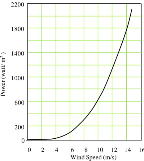
Figure 2.3 Power in the wind (at 150C and 1 atm).
A plot of equation (2-3) is shown in Fig.2.3 [34]. The power in the wind increases as the “cube” of the wind speed. This means that the doubling the wind speed increases the power by eight times. Equation (2-3) also suggests that the wind power is proportional to the swept area covered by the wind.
2.3.2 Power Captured by the Wind Turbine
A wind turbine converts the kinetic energy in the wind into mechanical energy using the rotor blades. The amount of energy which the wind transfers to the rotor depends on the density of the air, the rotor swept area, and the wind speed [34]. The rotor blades of the wind turbine capture only part of the available wind power, and the actual power extracted by a wind turbine is given by [34],[35]:
𝑃𝑇 = 𝐶𝑝× 𝑃𝑤𝑖𝑛𝑑 =21𝜌 𝐴 𝑣𝑤3 × 𝐶𝑝(𝜆, 𝛽) (2-4)
where,
PT = Turbine power (W)
0 2 4 6 8 10 12 14 16 Wind Speed (m/s)
2200
1800
1400
1000
600
200
P
o
w
e
r
(w
a
tt
/
m
2)
19
CP = Coefficient of performance or power coefficient known as Betz Limit. 𝐶𝑝
is the turbine rotor power coefficient, which is a function of tip speed ratio (λ) and pitch angle (β).
Equation (2-4) indicates that there are three options for increasing the power captured by a wind turbine. These are:
wind speed vw,
power coefficient CP, and
Swept area A=πl2, where l is the blade length
Wind speed cannot be controlled. Therefore, the wind turbine should be located in regions where the wind speed is high to increase the captured power. The captured power is a cubic function of wind speed. Doubling the average wind speed would increase the wind power by eightfold [35].
The German engineer Betz showed that the maximum power extracted from an air stream is 16/27 or 0.59 of the theoretical available power [35].Only 59% of the wind power can be captured by a wind turbine even if the power losses are neglected. The power coefficient of a modern turbine usually varies from 0.2 to 0.5 depending on the turbine speed and number of blades. For a three blade turbine with a rotor diameter of 82 m and power coefficient of CP=0.36, the captured power is 2 MW at a wind speed of
12 m/s and air density of ρ=1.225 kg/m3 [35]. Fig. 2.4 shows typical 𝐶𝑝− 𝜆 characteristics.
Figure 2.4. Power coefficients versus tip speed ratio.
6 8 10 12 14 16 18 20 22 24 26 28 Tip Speed Ratio, λ
0.05
CP max
λopt
0.15 0.25 0.35 0.45
P
o
w
e
r
C
o
e
ff
ic
ie
n
t
20
The coefficient of performance of a wind turbine is influenced by the tip-speed to wind speed ratio (TSR), which is given by [35]:
𝑇𝑆𝑅 = 𝜆 =ɷ𝑚 𝑅
𝑣𝑤 (2-5)
𝑣𝑤 = ɷ𝑚𝜆 𝑅 (2-6)
where,
ωm = the mechanical speed of the turbine rotor (rpm) R = the radius of the turbine (m).
By substituting vw from equation (2-6) into equation (2-4), the turbine power can be
written as;
𝑃𝑇 =12𝜌 𝐴 𝐶𝑝(ɷ𝑚𝜆 𝑅) 3
(2-7)
2.3.3 Optimum Power Extraction from a Variable Speed Wind Turbine
The wind turbine can produce maximum power when the turbine operates at maximum
p
C (i.e. at Cp_opt) as indicated in equation (2-4). Therefore, the rotor speed should be
kept at an optimum value of the tip speed ratio,opt to ensure maximum power
extraction from the wind. If there is any change in wind speed the turbine rotor speed should be adjusted accordingly.
The target optimum power can be written from equation (2-7) as;
𝑃𝑚_𝑜𝑝𝑡 = 0.5𝜌 𝐴𝐶𝑝_𝑜𝑝𝑡(ɷ𝑚_𝑜𝑝𝑡𝜆 ×𝑅
𝑜𝑝𝑡 )
3
= 𝐾𝑜𝑝𝑡(ɷ𝑚_𝑜𝑝𝑡)3 (2-8)
where, 𝐾𝑜𝑝𝑡 = 0.5𝜌 𝐴𝐶𝑝_𝑜𝑝𝑡(𝜆𝑅
𝑜𝑝𝑡)
3
(2-9)
ɷ𝑚_𝑜𝑝𝑡 = 𝜆𝑜𝑝𝑡𝑅 𝑣𝑤 = 𝐾𝑤𝑣𝑤 (2-10)
𝐾𝑤 = 𝜆𝑜𝑝𝑡
21
So the target optimum torque can be given by
𝑇𝑚_𝑜𝑝𝑡 = 𝑃𝑚_𝑜𝑝𝑡/ɷ𝑚_𝑜𝑝𝑡 = 𝐾𝑜𝑝𝑡(ɷ𝑚_𝑜𝑝𝑡)2 (2-11)
The optimum torque can be calculated from the optimum power as shown in equation (2-11). When the generator speed below the rated speed, the generator follows the equation (2-8). If the generator speed exceeds the rated speed, the wind turbine energy capture must be limited by applying pitch control or driving the machine to the stall point [23].
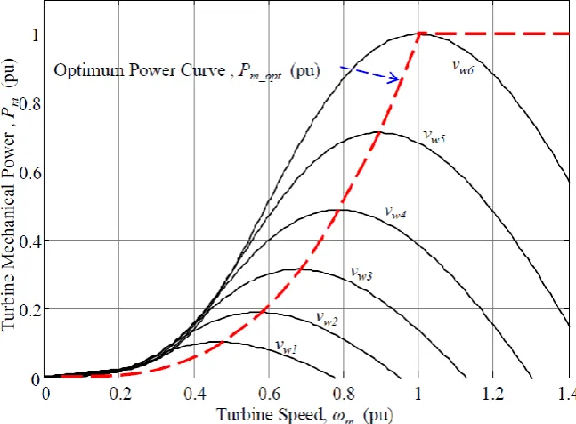
[image:45.595.163.487.489.727.2]
For a specific wind speed, output power of a wind turbine varies with turbine speed. The mechanical power generated by a wind turbine as a function of the rotor speed for different wind speed is shown in Fig. 2.5 [23]. The optimum power curve which defines maximum energy capture from the fluctuating wind is also shown in Fig 2.5. The controller should regulate the turbine speed to ensure the operation of the turbine keep the turbine on this curve as the wind speed changes. As shown in Fig.2.5, there is a matching turbine rotor speed which produces maximum power for any given wind speed. If the controller can properly designed to follow the variation in wind speed, the wind turbine will capture maximum power at any speed within the operating range [23].
22
2.3.4 Stream Tube Model of Air Flow for Theoretical Maximum Power Extraction
In 1919, the German physicist Albert Betz first formulated the derivation of maximum power that can be extracted from the wind [34]. Betz started the analysis by imagining what happens to the wind as it flows through the blades of wind turbine. As indicated in Fig.2.6, The downwind velocity is lower than upwind velocity due to energy capture by the wind turbine. The wind leaving the turbine blades has a lower velocity and pressure, causing the air to expand downwind of the turbine [34]. An envelope drawn around the air mass that passes through the turbine forms a “stream tube” as shown in Fig.2.6 [34]. The downwind velocity is lower than upwind velocity due to energy capture by the wind turbine. What Betz showed was that an ideal wind turbine would slow the wind to one-third of its original speed [34].
The power extracted by the blades PT is equal to the difference in kinetic energy
between the upwind and downwind air flows [34]:
𝑃𝑇 = 12𝑚(𝑣𝑤12 − 𝑣
𝑤22 ) (2-8)
where,
vw1 = upwind velocity of the undisturbed wind (m/s)
vwT = velocity of the wind through the plane of the rotor blades (m/s) vw2 = downwind velocity (m/s)
𝑚̇ = mass flow rate of air within the stream tube
The mass flow rate at the plane of the rotor with a swept area A is
𝑚̇ = 𝜌𝐴𝑣𝑤𝑇 (2-9)
By assuming that the velocity of the wind through the plane of the rotor is the average of the upwind and downwind speeds, we get [34],
𝑃𝑇 =12𝜌𝐴 (𝑣𝑤1+𝑣2 𝑤2) (𝑣𝑤12 − 𝑣𝑤22 ) (2-10)
23
Figure 2.6. Wind leaving the turbine slows and expands as a portion of its kinetic energy is extracted by
the wind turbine, forming the stream tube shown [34].
𝑥 =
𝑣𝑤2𝑣𝑤1 (2-11)
𝑣𝑤2= 𝑥𝑣𝑤1 (2-12)
𝑃𝑇 =12𝜌𝐴 (𝑣𝑤1+𝑥𝑣𝑤1
2 ) (𝑣𝑤12 − 𝑥2𝑣𝑤12 ) (2-13)
𝑃𝑇 =12𝜌𝐴𝑣𝑤13 ×12[(1 + 𝑥)(1 − 𝑥2)] (2-14)
The first part of equation (2-14) shows the power available in the wind and the second part indicate the fraction of the wind power that is extracted by the blades. The second part indicates the efficiency of the wind turbine, usually represented by power coefficient Cp. Thus, the rotor efficiency is given by
CP = 1
2(1 + 𝑥)(1 − 𝑥
2) (2-15)
Therefore, the fundamental relationship for the power captured by the rotor blades is given by
𝑃𝑇 =12𝜌𝐴𝑣𝑤13 × 𝐶𝑃 (2-16)
Downwind speed Upwind
speed
vw1
vw2
24
For maximum possible rotor efficiency, the derivative of equation (2-15) with respect to x would be equal to zero [34]:
𝑑𝐶𝑃
𝑑𝑥 = 1
2[(1 + 𝑥)(−2𝑥) + (1 − 𝑥
2)] = 0
12[(1 + 𝑥)(−2𝑥) + (1 + 𝑥)(1 − 𝑥)] = 0
12[(1 + 𝑥)(1 − 3𝑥)] = 0
𝑥 = −1 𝑜𝑟 1/3
∴ 𝑥 =𝑣𝑤2
𝑣𝑤1 = −1 𝑜𝑟 1/3
𝑣𝑤2 = −𝑣𝑤1 𝑜𝑟 𝑣𝑤2 =
1 3𝑣𝑤1
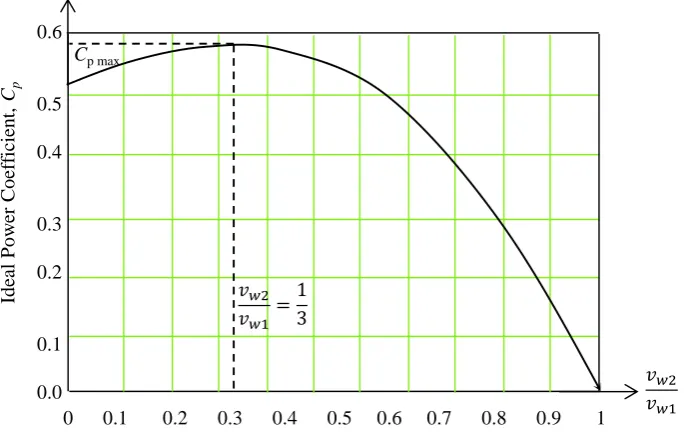
However, in reality upwind speed and downwind speeds are not equal and opposite. The blade efficiency will be maximum if it slows the wind to one-third of its upstream velocity as shown in Fig.2.7 [34].
Substituting x = 1/3 in equation (2-15), the theoretical maximum rotor blade efficiency is given by
Rotor efficiency = CP = 1
2(1 + 𝑥)(1 − 𝑥2)=0.593=59.3% (2-17)
Therefore, the maximum theoretical efficiency of a wind turbine rotor is 59.3%, which is called the Betz efficiency or Betz’ law[34]. For a given wind speed, the wind turbine rotor efficiency is a function of the rate at which the rotor rotates. When the rotor rotates too slowly, the efficiency drops as the turbine blades are bypassing too much wind. When the rotor rotates too fast, the turbine efficiency is dropped as the turbulence caused by one blade increasingly affects the blade that follows [34]. The Betz factor is a theoretical maximum power coefficient. But there are other effects which can cause decrease in maximum power coefficient. These are [34]:
rotation of the wake behind the rotor,
25
Fig. 2.8 shows actual wake rotation behind the turbine. The overall turbine efficiency is a function of both power coefficient 𝐶𝑝, mechanical and electrical efficiency of wind turbine generator. The overall turbine efficiency 𝜂𝑜𝑣𝑒𝑟𝑎𝑙𝑙, is given by [36]:
𝜂𝑜𝑣𝑒𝑟𝑎𝑙𝑙 = 𝐶𝑝 𝜂𝑚𝑒𝑐ℎ+𝑒𝑙𝑒𝑐𝑡𝑟𝑖𝑐𝑎𝑙 (2-18)
[image:49.595.152.496.285.504.2]Fig. 2.9 shows tip speed ratio verses maximum power coefficient, which indicates losses due to wake rotation, which is significant at low tip speed ratio [36].
Figure 2.7 Ideal power coefficient verses vw2/vw1.
Figure 2.8 Stream tube model including the rotating wake behind a turbine like energy converter.
Id
ea
l
P
o
w
er
C
o
ef
ficien
t,
Cp
0.6
0.5
0.4
0.3
0.2
0.1
0.0
Cp max
0 0.1 0.2 0.3 0.4 0.5 0.6 0.7 0.8 0.9 1
26
Figure 2.9 Betz factor, rotor real power coefficient considering wake rotation and losses due to wake rotation.
2.4 Influence of the Number of Turbine Blades on the Rotor Power
Coefficient
The performance of one, two, three and four blades wind turbine is shown in Fig.2.10. A one blade wind turbine requires higher wind speed to achieve maximum power coefficient. The power co-efficient of a wind turbine increases by about 10% from one blade to two blades, 4% for two blades to three blades and 2% for three blades to four blades rotor [36]. The higher the turbine blade numbers the higher the power coefficient [36]. A trade-off needs to be made in choosing the number of blades in a wind turbine considering size, cost and performances. The three blades rotor presents the best trade-off between mechanical stress, acoustic noise, cost, and rotational speed for large wind turbines [35].
Fig.2.11 (a), (b) and (c) show wind turbine with one, two and three blades, respectively. One blade rotor is aerodynamically unbalanced and moment of inertia changes due to rotation. It shows very high dynamic and mechanical stress [36]. Two blades rotor is dynamically unbalanced and moment of inertia changes due to rotation. It has rotor pulsating profile, similar to a rotating rod. Three blades rotor is aerodynamically balanced and moment of inertia does not change due to rotation [36].
0 1 2 3 4 5 6 7 8 9 10
0.6
0.59
0.5
0.4
0.3
0.2
0.1
0.0
Tip speed ratio,
P
o
w
er
Co
ef
fic
ie
n
t,
Cp Betz factor ( Ideal case / No wake rotation )
Losses due to wake rotation
![Figure 1.1 Global wind power capacity (2000-2013) [1].](https://thumb-us.123doks.com/thumbv2/123dok_us/8418929.329226/26.595.56.503.87.354/figure-global-wind-power-capacity.webp)