Abstract—The nine-arm modular multilevel converter (9A-MMC) has been recently proposed as a reduced MMC topology variation for six-phase drive applications, with 25% reduction in the number of employed arms and associated components, compared to a standard dual three-phase MMC, however with a limited output voltage amplitude. This paper proposes a hybrid 9A-MMC comprised of half-bridge submodules (SMs) in both the upper and lower arms, and full-bridge SMs in the middle arms. By employing the negative-voltage state of the full-bridge SMs, the hybrid 9A-MMC avoids the limitations imposed on the dc-link voltage utilization, while achieving further reduction in the component count, compared to a standard 9A-MMC with identical half-bridge SMs. The operating principles of the proposed hybrid 9A-MMC are illustrated with mathematical analysis, while its characteristics are verified through both simulation and experimentation. An assessment of the proposed topology quantifying its employed components is also provided, in comparison to other MMC-based six-phase machine drives.
Index Terms—Hybrid modular multilevel converter (MMC), medium-voltage machine drive, nine-arm MMC, six-phase machines.
Manuscript received May 24, 2018; revised August 23, 2018 and October 13, 2018; accepted October 24, 2018. (Corresponding author: Mohamed S. Diab)
M. S. Diab is with the Department of Electronic and Electrical Engineering, University of Strathclyde, Glasgow G1 1XQ, U.K., and also with the Electrical Engineering Department, Faculty of Engineering, Alexandria University, Alexandria 21544, Egypt (e-mail: [email protected]).
A. A. Elserougi is with the Electrical Engineering Department, Faculty of Engineering, Alexandria University, Alexandria 21544, Egypt (e-mail: [email protected])
A. M. Massoud is with the Department of Electrical Engineering, Qatar University, Doha 2713, Qatar (e-mail: ahmed.massoud @qu.edu.qa).
S. Ahmed is with the Department of Electrical Engineering, King Abdullah University of Science and Technology, Thuwal 23955-6900, Saudi Arabia (e-mail: [email protected]).
B. W. Williams is with the Department of Electronic and Electrical Engineering, University of Strathclyde, Glasgow G1 1XQ, U.K. (e-mail: [email protected]).
I. INTRODUCTION
ITH the wide deployment of high-power applications in various industry sectors, including both rotary and traction areas, the power level requirement of the adjustable-speed drives is increasing to scores of megawatts, triggering the need for high-power driving at the medium-voltage (MV) level [1]. Over the past decades, the development of MV machine drives has been an active research area, where different MV converter topologies have found their application in the market [2]-[3]. Among them, the multilevel converter topologies have established themselves as a mature technology which has been favored by MV drives manufacturers, being able to provide a stepped output voltage waveform that reduces the 𝑑𝑣 𝑑𝑡⁄ stresses at the motor terminals. However, with the state-of-the-art multilevel converter topologies experiencing challenging shortcomings, the modular multilevel converter (MMC) has robustly found its way as a promising competitor for medium- to high-voltage high-power applications, outperforming its counterparts [4]. Being in the multilevel category, the MMC inherits the advantages of the state-of-the-art multilevel converter topologies, while solely enjoying the features of modularity, scalability, redundancy, and reliability [5]. These advantages promoted the MMC to be the next generation machine-drive technology, where it has been addressed, in this regard, within numerous diversified studies [6]-[9].
Over the time, three-phase machines have been adopted as a standard choice for motor drives realization. Nonetheless, in the last few decades, multiphase machines have reemerged as a potential alternative for various industrial applications, motivated by the advancement in power electronics, which facilitates synthesizing any number of phase voltages [10]. Multiphase machines have unique advantages over their three-phase counterparts, that can briefly be highlighted in the fault tolerance, high power density, reduced torque ripple and per-phase stator current, and lower dc-link current harmonic of the multiphase drive system. Consequently, multiphase drives are progressively breaking the technical barriers, finding a place in applications where reliability and fault tolerance are a prime concern [11]-[13].
Being the most applicable winding arrangement, six-phase machines, with either symmetrical or asymmetrical winding
A Hybrid Nine-Arm Modular Multilevel
Converter for Medium-Voltage
Six-Phase Machine Drives
Mohamed S. Diab,
Student Member
,
IEEE,
Ahmed A. Elserougi,
Senior Member, IEEE
,
Ahmed M. Massoud,
Senior Member
,
IEEE
, Shehab Ahmed,
Senior Member
,
IEEE
,
and Barry W. Williams
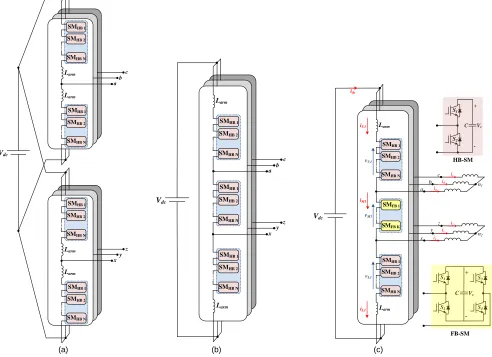
(a) (b) (c)
Fig. 1 Six-phase machine drive using (a) a 12A-MMC (b) a 9A-MMC and (c) a hybrid 9A-MMC.
layouts, have been the focus of attention among the numerous multiphase possibilities. The specific attraction of six-phase machines versus other possible alternatives typically returns to their ready adaptation with standard three-phase converter topologies. Through an enriched body of literature, six-phase machines have been studied with different aspects pertinent to their modeling, control, and applications [14]-[19].
With the dual three-phase inverter is the off-the-shelf drive topology for six-phase machines, dual three-phase MMC has been applied to drive both asymmetrical and symmetrical MV six-phase machines in [20] and [21], respectively. Nonetheless, the increased number of inverter legs and employed IGBTs fostered the need for topology variation to fulfill the requirements in a more economic and efficient way. That is, a reduced MMC structure, denoted as the nine-arm MMC (9A-MMC), has been recently adopted as an MV six-phase machine drive with 25% reduction in both silicon area and reactive elements [22]-[24]. However, as with most reduced component-count topologies, performance tradeoff was unavoidable where limitations were imposed on the utilization of the dc-link voltage supplying the 9A-MMC. That is, the dc-link voltage is increased by 50% to achieve the same level of power delivery, which counter-balances the scored merits.
To eliminate the imposed restriction of the attainable voltage amplitude, this paper proposes a hybrid design of the
9A-MMC, which achieves the same performance as the dual three-phase MMC, while employing at most the same number of IGBTs and a lower number of submodule (SM) capacitors, compared to a traditional MMC. The proposed hybrid 9A-MMC combines half-bridge submodules (HB-SMs) in both the upper and lower arms, and full-bridge submodules (FB- SMs) only in the middle arms. That is, the modulation index of the 9A-MMC is promoted by employing the FB-SM’s negative-voltage state which enhances the dc-link voltage utilization without any further compromise [25].
II. MMC-BASED SIX-PHASE MACHINE DRIVES The traditional approach to drive a six-phase machine using the MMC topology is to employ a dual three-phase MMC, as shown in Fig. 1a, to generate two sets of three-phase voltages electrically shifted by 30° or 60° for either asymmetrical- or symmetrical-winding machines, respectively. The dual three-phase MMC incorporates six three-phase-legs each composed of two arms connected in series through arm inductor, 𝐿𝑎𝑟𝑚. Each arm is formed by 𝑁 series connected SMs. The SM is commonly an HB cell employing a dc capacitor of an equivalent capacitance 𝐶 and a nominal voltage 𝑉𝑐. Since the dual three-phase MMC employs twelve arms, it is denoted hereafter as the twelve-arm MMC (12A-MMC).
With the increased number of IGBTs and SM capacitors employed by the 12A-MMC, a 9A-MMC has been presented Vdc
Larm
Larm
ab c
SMHB 1
SMHB 2
SMHB N
SMHB 1
SMHB 2
SMHB N
Larm
Larm
xy z
SMHB 1
SMHB 2
SMHB N
SMHB 1
SMHB 2
SMHB N
Larm
Vdc
a b c
x y z
Larm
SMHB 1
SMHB 2
SMHB N
SMHB 1
SMHB 2
SMHB N
SMHB 1
SMHB 2
SMHB N
c b a
Vdc
C
+
-Vc
HB-SM
S1
S2
C
+
-Vc
FB-SM
S1
S2
S3
S4
n1 ic
ib
ia
y
x n2
iy
ix z iz iU1
vU1
vM1
iL1
vL1
idc
Larm
SMHB 1
SMHB 2
SMHB N
Larm
SMHB 1
SMHB 2
SMHB N SMFB 1
as a topology variation with a reduced structure that alleviates the size of the six-phase machine drive. As the name implies, the 9A-MMC employs nine arms evenly assorted in three legs each formed by upper, middle, and lower arms, all employing HB-SMs. The six-phase load terminals are realized through the intermediary points between each two series connected arms, as shown in Fig. 1b. The 25% reduction in the number of arms, compared to the 12A-MMC, arises from the fact that the 9A-MMC is a direct consequence of integrating two three-phase MMCs, with dual function middle arms. The 9A-MMC is intrinsically inspired from the nine-switch voltage-source inverter which has been firstly evolved to supply two independent three-phase machines [26], while recently has been adopted as a six-phase machine drive [19].
The utilization of the 9A-MMC reduces the number of employed IGBTs and their accessories in addition to both arm inductors and SM capacitors and their measuring transducers, which eventually reduces the system size, complexity, and cost. Notwithstanding, similar to the nine-switch inverter, the 9A-MMC experiences limited voltage amplitude, where the utilization of the dc-link voltage, 𝑉𝑑𝑐, is reduced to ⅓, compared to the 12A-MMC. That is, the voltage across any of the upper, middle, and lower arms ranges between 0 and ⅔𝑉𝑑𝑐, where the SM capacitor voltage, of all arms, is reduced to 2𝑉𝑑𝑐⁄3𝑁. This operational limit arises due to the dual functionality of the middle arms, which necessitates increasing the dc-link voltage by 50% to deliver the same amount of power as the 12A-MMC.
III. HYBRID NINE-ARM MMC
To promote the dc-link voltage utilization of the 9A-MMC, with further reduction in topology components, this paper proposes a hybrid 9A-MMC which inherits the typical structure of the standard 9A-MMC, however, incorporates mixed SM cells. The hybrid 9A-MMC is shown in Fig. 1c, feeding a six-phase machine with isolated neutral points. Both the upper and lower arms are formed by 𝑁 series connected HB-SMs, while the middle arm is composed by 𝐾 series connected FB-SMs. The value of 𝐾 is determined as a portion of 𝑁, depending on the phase shift between the two sets of three-phase output voltages.
A. Arm Voltages
Referring to Fig. 1c, a general form for the two three-phase voltage sets are:
𝑣𝑗𝑛1= 𝑉𝑜cos (𝜔𝑡 −2𝜋
3 𝑚) , 𝑚 = 0, 1, 2 for 𝑗 = 𝑎, 𝑏, 𝑐 (1a)
𝑣𝑗𝑛2= 𝑉𝑜cos (𝜔𝑡 −2𝜋
3 𝑚 + ∅) , 𝑚 = 0, 1, 2 for 𝑗 = 𝑥, 𝑦, 𝑧 (1b)
where 𝜔 is the output angular frequency,∅ is the phase angle between the two voltage sets, and 𝑉𝑜 is the magnitude of the output phase-voltage, and is defined as same as the voltage magnitude of traditional 12A-MMC as follows.
𝑉𝑜= 1
[image:3.612.318.563.51.163.2]2 𝑀𝑉𝑑𝑐 (2)
Fig. 2 Middle-arm voltage variation relative to the phase-shift angle (M = 1).
(a) (b)
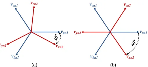
Fig. 3 A vector diagram for the six-phase voltages required by (a) asymmetrical machine and (b) symmetrical machine.
where 𝑀 is the modulation index, ranging from 0 to 1, while 𝑉𝑑𝑐 is the input dc voltage. Accordingly, both the upper and lower arms are controlled to generate a unidirectional voltage ranging from 0 to 𝑀𝑉𝑑𝑐. Considering leg-1 of the hybrid 9A-MMC, which provides the machine phase-terminals 𝑎 and 𝑥, the voltage across both the upper and lower arms are given as shown in (3), where the subscripts 𝑈 and 𝐿 are utilized to denote the upper and lower arm, respectively, while the subscript 𝑀is utilized hereafter to refer to the middle arm.
𝑣𝑈1= 1
2𝑉𝑑𝑐[1 − 𝑀 cos(𝜔𝑡)] (3a)
𝑣𝐿1= 1
2 𝑉𝑑𝑐[1 + 𝑀 cos(𝜔𝑡 + ∅)] (3b)
The voltage balance between the dc-link voltage and the hybrid 9A-MMC legs implies the middle-arm voltage be bidirectional, as follows.
𝑣𝑀1= 𝑉𝑑𝑐− 𝑣𝑈1− 𝑣𝐿1 =1
2𝑀𝑉𝑑𝑐 √2(1 − cos ∅) cos(𝜔𝑡 + 𝛼) (4)
𝛼 = tan−1 sin ∅
cos ∅ − 1 (5)
As demonstrated by (4), the magnitude of the middle-arm voltage depends on the phase angle ∅, which is graphically demonstrated in Fig. 2 for different values of ∅, at unity modulation index. It can be shown that, unlike both the upper- and lower-arm voltages, the middle-arm voltage is comprised only of an ac component with a magnitude that is directly proportional to the angle ∅, with a maximum swing of ±𝑉𝑑𝑐. The bidirectional middle-arm voltage can only be realized through the incorporation of FB-SMs in the middle arm, where the number of employed FB-SMs is determined
Vdc
-Vdc
0
vM
1
[V
]
ωt[deg]
van1
vbn1 vcn1
vxn2
vyn2
vzn2
60° van1
vbn1 vcn1
vxn2
vyn2
vzn2
[image:3.612.317.564.195.308.2]according to the angle ∅. Since the hybrid 9A-MMC is ultimately proposed as a six-phase machine drive, the angle ∅ will be either 30° or 60° depending on whether the machine has an asymmetrical or symmetrical winding layout, respectively, as vectorially represented in Fig. 3. That is, the magnitude of the middle-arm voltage is 0.258 𝑉𝑑𝑐 for asymmetrical machines and 0.5 𝑉𝑑𝑐 for symmetrical machines. Therefore, the number of employed FB-SMs in the middle arm is designed as 30% and 50% of the number of employed HB-SMs in either the upper or lower arms for asymmetrical and symmetrical machines, respectively.
B. Arm Currents
The machine currents (𝑖𝑎 and 𝑖𝑥) supplied by leg-1 are described by (6), where 𝐼𝑜is the current magnitude and 𝛿 is the machine power-factor angle.
𝑖𝑎= 𝐼𝑜cos(𝜔𝑡 − 𝛿) (6a)
𝑖𝑥= 𝐼𝑜cos(𝜔𝑡 + ∅ − 𝛿) (6b)
The arm currents are defined in relation to the machine currents as:
𝑖𝑈1= 𝑖𝑐𝑖𝑟𝑐+ 𝑖𝑎 (7a)
𝑖𝑀1= 𝑖𝑐𝑖𝑟𝑐 (7b)
𝑖𝐿1= 𝑖𝑐𝑖𝑟𝑐− 𝑖𝑥 (7c)
where 𝑖𝑐𝑖𝑟𝑐 is the circulating current passing through the dc loops comprising the dc side and each converter leg. The circulating current is fundamentally formed by a dc component associated with the active power transfer between the converter and the dc side, in addition to a series of low-order harmonics due to the SM capacitor voltage fluctuations in attempt to keep the voltage balance between the dc side and the converter legs. It is worth mentioning that in a standard MMC, the circulating current experiences only even-order harmonics, where the odd-harmonics appear differentially in the capacitor voltage fluctuation of both the upper- and lower-arm SMs due to the out-of-phase modulation of both lower-arms. Therefore, the influence of the odd-harmonics is cancelled in the circulating current. On the other side, the circulating current of the hybrid 9A-MMC experiences both even and odd harmonics, while their magnitudes depend on the modulation phase angle between both the upper and lower arms. Among these low-order harmonics, the second-order harmonic has the largest magnitude, and then the third-order harmonic with a lower magnitude. Due to its dominant effect, the second-order harmonic is suppressed through several approaches, while the effect of the remaining third-order harmonic on the circulating current can be fairly neglected without affecting the forthcoming analysis. Accordingly, the circulating current is assumed to be only the dc component, and is defined as one third of the dc input current, 𝑖𝑑𝑐, as follows.
𝑖𝑐𝑖𝑟𝑐= 𝑖𝑑𝑐
3 =
𝑀𝐼𝑜cos 𝛿
2 (8)
C. SM Capacitor Voltage
Due to the asymmetric operational behavior of the hybrid 9A-MMC, the capacitive energy stored in the middle arm will have different alternation than that of both the upper and lower arms, which is eventually manifested in the corresponding SM capacitor voltage with different ripple profiles. With the modulation of (3) and (4), the capacitor current, 𝑖𝐶, for an upper-, middle-, and lower-arm SM is described as:
𝑖𝐶 𝑈1= 1
2[1 − 𝑀 cos(𝜔𝑡)] 𝑖𝑈1 (9a)
𝑖𝐶 𝑀1 = 1
2𝑀√2(1 − cos ∅)cos(𝜔𝑡 + 𝛼) 𝑖𝑀1 (9b)
𝑖𝐶 𝐿1= 1
2[1 + 𝑀 cos(𝜔𝑡 + ∅)] 𝑖𝐿1 (9c)
By integrating (9), the capacitor voltage fluctuation of SMs in the three arms is calculated as:
∆𝑣𝐶 𝑈1= 1 𝐶 ∫ 𝑖𝐶 𝑈1
𝑡
0 𝑑𝑡
= 𝐼𝑜
4𝜔𝐶[√4 + cos
2𝛿 (𝑀4− 4𝑀2) sin(𝜔𝑡 + 𝛽)
− 𝑀 sin(2𝜔𝑡 − 𝛿)] (10a)
∆𝑣𝐶 𝑀1= 1 𝐶 ∫ 𝑖𝐶 𝑀1
𝑡
0 𝑑𝑡
= [𝑀 2𝐼
𝑜cos 𝛿
4𝜔𝐶 √2(1 − cos ∅)] sin(𝜔𝑡 + 𝛼) (10b)
∆𝑣𝐶 𝐿1= 1 𝐶 ∫ 𝑖𝐶 𝐿1
𝑡
0 𝑑𝑡
= 𝐼𝑜
4𝜔𝐶[−√4 + cos
2𝛿 (𝑀4− 4𝑀2) sin(𝜔𝑡 + 𝛽)
− 𝑀 sin(2(𝜔𝑡 + ∅) − 𝛿)] (10c)
where 𝛽 is given as:
𝛽 = tan−12 tan 𝛿
𝑀2− 2 (11)
D. SM Capacitance Design
From (10), the capacitor voltage ripple for both the upper- and lower-arm SMs pulsate due to both the first- and second-frequency harmonics. Whereas, the middle-arm SM has a capacitor voltage ripple pulsating at the fundamental frequency. Therefore, the middle-arm SM capacitance design is quite different compared to that of both the upper- and lower-arm SMs’ capacitance, for the same voltage-ripple profile.
(a) (b)
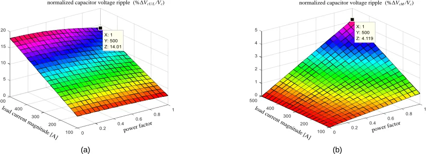
Fig. 4 Normalized peak-to-peak capacitor voltage ripple for various operating conditions of load current and power factor, for (a) upper- and lower-arm SMs and (b) middle-arm SM. (𝑀=1, 𝑓=50 Hz, 𝐶=5 mF, ∅ =30°, and 𝑉𝑐=2 kV)
[image:5.612.83.522.65.224.2](a) (b)
Fig. 5 Normalized peak-to-peak capacitor voltage ripple for various operating conditions of operating frequency and modulation index, for (a) upper- and lower-arm SMs and (b) middle-arm SM. (𝐼𝑜=250 A, 𝛿=35°, 𝐶=5 mF, ∅=30°, and 𝑉𝑐=2 kV)
significantly lower than that of both the upper- and lower-arm SMs. In addition, while the middle-arm SM voltage ripple is in direct proportion to the power factor, both the upper- and lower-arm SM voltage ripple are inversely proportional to the power factor. To quantify the voltage ripple diversity, the maximum voltage ripple ratio between both the upper- and lower-arm SMs and the middle-arm SMs is recorded as 3.4. In a similar way, Fig. 5 shows the voltage ripple profile in response to both operating frequency and modulation index variation. Fig. 5a shows that the voltage ripple of both upper- and lower-arm SMs is slightly inversely proportional to the modulation index, but significantly inversely proportional to the operating frequency. On the other hand, the middle-arm SM voltage ripple, shown in Fig. 5b, is slightly increasing with either increased modulation index or operating frequency. The ratio between the maximum recorded voltage ripple in Fig. 5a to Fig. 5b is 4.5. It is worth mentioning that the results in both Figs. 4 and 5 assume the hybrid 9A-MMC is driving an asymmetrical machine, where ∅ is set to 30°. Unlike both the upper and lower arms, the middle-arm SM capacitor voltage ripple depends on the phase angle ∅, where it is almost doubled when the hybrid 9A-MMC drives a symmetrical six-phase machine, compared to an asymmetrical one. Nonetheless, the middle-arm SM capacitance can be
reduced to quarter and half the upper- and lower-arm SM capacitance, for asymmetrical and symmetrical machines, respectively.
IV. CONTROL METHOD
A phase disposition PWM-based modulator, with a switching frequency 𝑓𝑠𝑤, is utilized for each leg of the hybrid 9A-MMC to command a varying number of SMs to be inserted at each time instant in the different arms. This is schematically illustrated in Fig. 6 for one leg of the hybrid 9A-MMC. Both the upper- and lower-arm reference voltages, as given by (3), are utilized as input to the modulator which accordingly determines the necessary number of HB-SMs to be inserted in both the upper and lower arms, as denoted by 𝑛𝑈1 and 𝑛𝐿1, respectively. To ensure a zero voltage summation in the outer loop, the number of FB-SMs to be inserted in the middle arm is calculated as 𝑛𝑀1 = 𝑁 − 𝑛𝑈1− 𝑛𝐿1, where a limiter with a bandwidth of either ±0.3𝑁 or ±0.5𝑁 is utilized for the asymmetrical and symmetrical operation mode of the hybrid 9A-MMC, respectively. The positive sign of 𝑛𝑀1 indicates operating the middle-arm FB-SMs under positive voltage state (that is, positive SM output voltage), while the negative sign indicates a negative output voltage state.
power fac tor
load current
magnit ude [A
]
normalized capacitor voltage ripple (%ΔVcU/L /Vc)
power factor
normalized capacitor voltage ripple (%ΔVcM /Vc)
load cur rent ma
gnitude [A]
normalized capacitor voltage ripple (%ΔVcU/L /Vc)
modulation in dex frequency [Hz]
modulation in dex frequency [Hz]
[image:5.612.89.522.260.420.2]Fig. 6 A schematic diagram for the modulation and control of one leg of the hybrid 9A-MMC.
A capacitor voltage balancing algorithm is applied to maintain all of the SM capacitors balanced around the nominal value, which is realized by a selection mechanism based on capacitor voltage measurements at each switching instance. This mechanism sorts the SM capacitor voltages and then decides which individual SM is inserted or bypassed, according to the arm current direction [27]. It should be noted that, although the middle-arm current is unidirectional, the FB-SMs can charge and discharge their capacitors by changing the arm-current polarity passing through the capacitors when inserted in the conduction path.
V. VERIFICATION
The performance of the proposed hybrid 9A-MMC has been examined using both simulation and experimentation, with the parameters listed in Table I.
A. Verification using RL Load
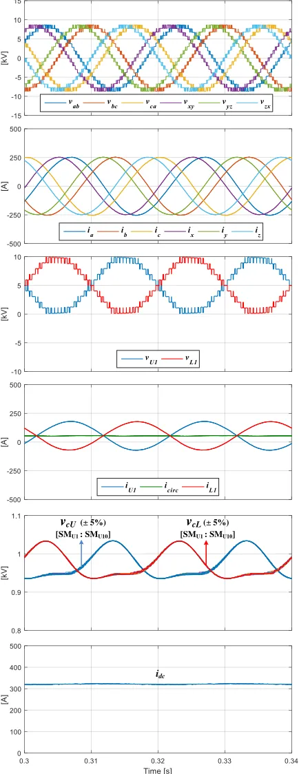
A 3.2 MW MATLAB/SIMULINK simulation model is used to verify the features of the proposed hybrid 9A-MMC while feeding a six-phase RL load (R=15 Ω, L=30 mH), in comparison to the traditional 12A-MMC. The simulation results are shown in Figs. 7 and 8 for an asymmetrical modulation (∅=30°) of both the 12A-MMC and hybrid 9A-MMC, respectively. Common to both topologies, the number of HB-SMs in both the upper and lower arms is 10. That is, the number of FB-SMs in the middle arm of the hybrid 9A-MMC is 3. In both Figs. 7 and 8, the six-phase line voltages and load currents show high quality sinusoidal waveform with 30° phase shift between the abc and xyz three-phase sets. Both the upper- and lower-arm voltages, of both topologies, step from 0 to 10 kV through eleven voltage levels. Whereas, the middle-arm voltage of the hybrid 9A-MMC is bidirectional and steps with ±3 kV amplitude.
Using a parallel-resonant filter, the second-order harmonic is eliminated in the circulating current of both topologies [23]. That is, both the upper- and lower-arm currents of the 12A-MMC show a good out-of-phase sinusoidal profile, where the circulating current is a dc component. Similarly, both the upper- and lower-arm currents of the hybrid 9A-MMC are showing good sinusoidal profile with a doubled value
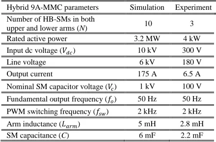
TABLEI
PARAMETERS FOR SIMULATION AND EXPERIMENT
Hybrid 9A-MMC parameters Simulation Experiment
Number of HB-SMs in both
upper and lower arms (N) 10 3
Rated active power 3.2 MW 4 kW
Input dc voltage (𝑉𝑑𝑐) 10 kV 300 V
Line voltage 6 kV 180 V
Output current 175 A 6.5 A
Nominal SM capacitor voltage (𝑉𝑐) 1 kV 100 V
Fundamental output frequency (𝑓𝑜) 50 Hz 50 Hz
PWM switching frequency (𝑓𝑠𝑤) 2 kHz 2 kHz
Arm inductance (𝐿𝑎𝑟𝑚) 5 mH 2.8 mH
SM capacitance (C) 6 mF 2.2 mF
compared to that of the 12A-MMC, while the middle-arm current (equivalent to the circulating current) exhibits a dc component with slight fluctuation due to the influence of the uncompensated third-order harmonic which clearly appears in the dc input current with a tripled value.
Investigating the SM capacitor voltage, both the upper- and lower-arm SMs, of both topologies, pulsate due to both the first- and second-frequency components, with a ±5% voltage ripple. To maintain such an equal band of voltage ripple, the SM capacitance is set to 3 mF and 6 mF for the 12A-MMC and the hybrid 9A-MMC, respectively. The middle-arm SM capacitor voltage of the hybrid 9A-MMC pulsates with the fundamental frequency at ±1.4% using 6 mF SM capacitance as well. That is, to achieve the same ±5% voltage ripple profile across the different-arm SM capacitors, the middle-arm SM capacitance can be reduced to 1.3 mF.
B. Verification using Six-Phase Machine
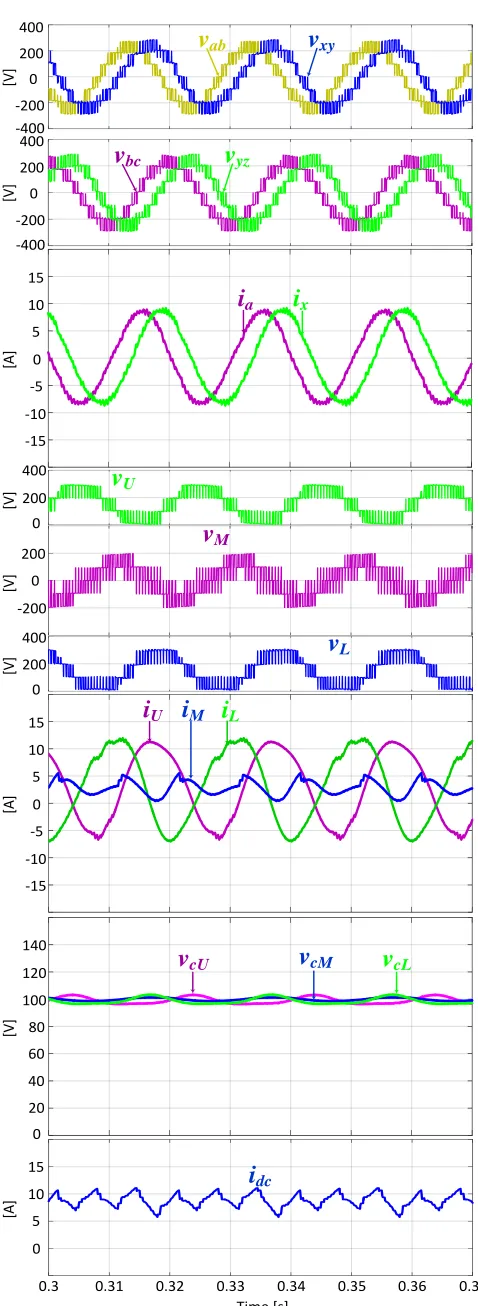
The performance of the hybrid 9A-MMC is examined when driving a symmetrical six-phase machine, in an open-loop scheme, through both simulation and experimentation at the same operating conditions. That is, a scaled-down laboratory prototype is built to drive a symmetrical six-phase machine constructed by rewinding the stator of an existing three-phase induction machine with two identical three-phase single layer windings shifted in space by 60°. The constructed six-phase machine has half the number of turns per coil and same conductor cross sectional area, compared to the three-phase machine, to maintain the same copper volume. The three-phase machine is rated at 4 kW, 415 V (line-to-line), 50 Hz, 7.5 A, 1450 RPM with two pole pairs. After rewinding, the rated voltage is halved, while other rated values are maintained. The number of HB-SMs in each of the upper and lower arms is 3, while the number of FB-SMs in the middle arms is 2. The control algorithm is implemented using TMS320F28335 Texas Instruments DSPs.
Both simulation and experimental results are presented in Figs. 9 and 10, respectively, at the same scale to allow one-to-one comparison. In both figures, two line voltages of each three-phase set are shown to traverse with seven voltage levels, while the machine currents 𝑖𝑎 and 𝑖𝑥 are sinusoidal. Both the upper- and lower-arm voltages step between 0 and 300 V, while the middle-arm voltage is bidirectional, alternating with ±200 V. The upper- and lower-arm currents phase-disposition modulation
HB-SM capacitor voltage balancing
algorithm
vU1 nU1
vcU 1 : vcU N iU1
S1,S2
vL1
nL1
-+
-N
S1,S2
iM1
S1,S2
vcM 1 : vcM K
vcL 1 : vcL N iL1
S3,S4
[SMU1:SMUN]
[SMM1:SMMK]
[SML1:SMLN] Vdc
0
Vdc
N
fsw
FB-SM capacitor voltage balancing
algorithm
HB-SM capacitor voltage balancing
algorithm
nM1
[image:6.612.328.548.71.216.2]Fig. 7 Simulation results of the 12A-MMC while supplying an asymmetrical six-phase RL load.
are showing a sinusoidal profile, however, distorted with low-order harmonics since the circulating current has not been controlled to suppress its inherited harmonics. Therefore, both the second- and third-order harmonics are simultaneously affecting the arm-current waveforms, as clearly appear in the fluctuation of the middle-arm current, with 23% and 8%,
Fig. 8 Simulation results of the hybrid 9A-MMC while supplying an asymmetrical six-phase RL load.
respectively. These harmonics appear further enlarged in the supply current waveform since their instantaneous value is tripled. The capacitor voltage of both the upper- and lower-arm SMs have ±3% voltage ripple, while the middle-lower-arm SM capacitor has ±0.7% voltage ripple, where the capacitance of all SMs is 2.2 mF.
vcU (± 5%) [SMU1 : SMU10]
vcL (± 5%) [SMU1 : SMU10]
idc
vcU (± 5%) [SMU1 : SMU10]
vcL (± 5%) [SMU1 : SMU10]
vcM (± 1.4%) [SMM1 : SMM3]
[image:7.612.328.544.57.623.2] [image:7.612.62.279.58.620.2]Fig. 9 Simulation results of the hybrid 9A-MMC while supplying a symmetrical six-phase machine.
Fig. 10 Experimental results of the hybrid 9A-MMC while supplying a symmetrical six-phase machine (time scale: 10 ms/div).
[V
]
[V
]
0 200
-200 -400 400 0 200
-200 -400 400
v
bcv
yzv
abv
xy0
0 -5 -10 -15 5 10 15
[A
]
i
ai
x0 -5 -10 -15 5 10 15
[A
]
i
Ui
Mi
L0 20 40 60 80 100 120 140
[V
]
v
cUv
cMv
cL0 5 10 15
0.3 0.31 0.32 0.33 0.34 0.35 0.36 0.37 Time [s]
[A
]
i
dc0 200
-200 0 200
0 200 400 400
[V
]
[V
]
[V
]
v
Uv
Mv
L[200.0 V/div]
v
Lv
Mv
U[200.0 V/div]
v
bcv
yzv
abv
xyi
a[5.0 A/div]
i
x[5.0 A/div]
i
Ui
Mi
L[20.0 V/div]
v
cUv
cMv
cL [image:8.612.50.289.44.697.2] [image:8.612.317.565.50.682.2]TABLE II
QUANTITATIVE COMPARISON BETWEEN MMC-BASED SIX-PHASE MACHINE DRIVE TOPOLOGIES AT SAME DC-LINK VOLTAGE
12A-MMC 9A-MMC Hybrid 9A-MMC
∅ = 30° ∅ = 60°
DC link voltage 𝑉𝑑𝑐 𝑉𝑑𝑐 𝑉𝑑𝑐
Maximum AC voltage ½ 𝑉𝑑𝑐 ⅓ 𝑉𝑑𝑐 ½ 𝑉𝑑𝑐
Number of SMs 12N HB-SMs 9N HB-SMs 6N HB-SMs and 0.9N FB-SMs 6N HB-SMs and 1.5N FB-SMs
Number of IGBTs 24N 18N 15.6N 18N
Number of arm inductors 12 6 6
Number of SM capacitors 12N 9N 6.9N 7.5N
TABLE III
RATING AND PARAMETERS ASSESSMENT OF MMC-BASED SIX-PHASE MACHINE DRIVE TOPOLOGIES AT SAME POWER LEVEL
12A-MMC 9A-MMC Hybrid 9A-MMC
∅ = 30° ∅ = 60°
DC link voltage 𝑉𝑑𝑐 3𝑉𝑑𝑐⁄2 𝑉𝑑𝑐
IGBT rated voltage 𝑉𝑑𝑐⁄𝑁 𝑉𝑑𝑐⁄𝑁 𝑉𝑑𝑐⁄𝑁
IGBT rated current ⅙𝐼𝑑𝑐+ ½𝐼𝑜
2
9𝐼𝑑𝑐+ 2𝐼𝑜for upper-arm IGBTs,
2
9𝐼𝑑𝑐+ 𝐼𝑜 for middle-arm IGBTs, and
2
9𝐼𝑑𝑐+ 0.5𝐼𝑜for lower-arm IGBTs
⅓𝐼𝑑𝑐+ 𝐼𝑜for upper- and lower-arm IGBTs
and ⅓𝐼𝑑𝑐 for middle-arm IGBTs
Combined power rating 12𝑉𝑑𝑐𝐼𝑜+ 4𝑉𝑑𝑐𝐼𝑑𝑐 21𝑉𝑑𝑐𝐼𝑜+ 4𝑉𝑑𝑐𝐼𝑑𝑐 12𝑉𝑑𝑐𝐼𝑜+ 5.2𝑉𝑑𝑐𝐼𝑑𝑐 12𝑉𝑑𝑐𝐼𝑜+ 6𝑉𝑑𝑐𝐼𝑑𝑐
SM capacitance 𝐶
4𝐶 for upper-arm SMs,
2𝐶 for middle-arm SMs, and
𝐶 for middle-arm SMs
2𝐶 for upper- and lower-arm SMs
0.5𝐶 for middle-arm SMs 𝐶 for middle-arm SMs
Total capacitive stored energy 12𝑁 [½ 𝐶 (𝑉𝑑𝑐⁄ )𝑁2] 21𝑁 [½ 𝐶 (𝑉𝑑𝑐⁄ )𝑁2] 12.45𝑁 [½ 𝐶 (𝑉𝑑𝑐⁄ )𝑁2] 12.75𝑁 [½ 𝐶 (𝑉𝑑𝑐⁄ )𝑁 2]
Arm Inductance 𝐿 𝐿 𝐿
Total reactive elements 12𝑁𝐶 + 12𝐿 21𝑁𝐶 + 6𝐿 12.45𝑁𝐶 + 6𝐿 13.5𝑁𝐶 + 6𝐿
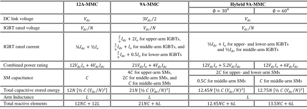
VI. ASSESSMENT OF THE PROPOSED HYBRID 9A-MMC Promoted by the inclusion of FB-SMs, the hybrid 9A-MMC achieves the same voltage utilization as the standard 12A-MMC, however with a reduced component count. Table II assesses the number of components employed by the hybrid 9A-MMC, for both asymmetrical and symmetrical operation, in comparison to both the standard 12A-MMC and 9A-MMC, while Table III assesses the IGBTs rating and reactive element design at the same power level and SM capacitor voltage ripple. While the IGBT rated voltage is identical for different SMs in both the 12A-MMC and the hybrid 9A-MMC, the rated current is doubled for both the upper- and lower-arm IGBTs, and is reduced by 40% for the middle-arm IGBTs of the hybrid 9A-MMC, compared to the 12A-MMC.
In [9], the SM capacitor voltage ripple has been analyzed in detail for a standard MMC topology, and categorized into first- and second-frequency ripple components, where it was shown that the first-frequency component is the dominant component in the SM capacitor voltage ripple. Since both the upper- and lower-arm currents of the hybrid 9A-MMC topology are twice the arm currents of a standard MMC, the first-frequency ripple component of the hybrid 9A-MMC is twice that of a standard MMC. Therefore, the SM capacitance of both the upper- and lower-arm SMs are designed as twice as the SM capacitance of a standard MMC SMs, for the same voltage ripple. Whilst, the middle-arm SM capacitance is selected as quarter and as half the upper-/lower-arm SM capacitance, for the asymmetrical and symmetrical designs of the hybrid 9A-MMC, respectively.
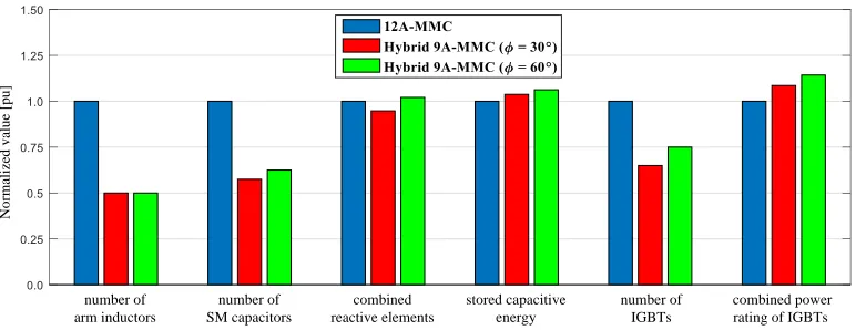
Fig. 11 shows a graphical assessment of the hybrid 9A-MMC in comparison to the 12A-9A-MMC, where the latter’s parameters are set as 1 pu, and are used as a reference for the former’s parameters. While the number of arm inductors is reduced by 50%, the number of SM capacitors is reduced by 42.5% and 37.5% for asymmetrical and symmetrical designs of the proposed topology, respectively. However, the sum of the total employed inductance and capacitance is almost the same for both the 12A-MMC and the hybrid 9A-MMC, while the total capacitive stored energy is slightly increased by 3.8% and 6.3% for the asymmetrical and symmetrical designs of the hybrid 9A-MMC, respectively. Also, the number of IGBTs is reduced by 35% and 25%; nonetheless, the combined power rating of the IGBTs is increased by 8.6% and 14.3%, where the values denote for the asymmetrical and symmetrical modes of the hybrid 9A-MMC, respectively.
[image:9.612.87.524.73.179.2] [image:9.612.43.568.205.392.2]Fig. 11 Graphical assessment of the proposed hybrid 9A-MMC in comparison to the 12A-MMC.
capacitors from EPOCS [30], [31], the volume of 6 mF, 3 mF, and 1.5 mF capacitors are 19 L, 11.56 L, and 2.88 L, respectively, all with 1.1 kV. Accordingly, the total capacitance size of the 12A-MMC (incorporating 12N
capacitors each with 3 mF) is 1387.2 L. Whereas, the total capacitance size of the hybrid 9A-MMC (incorporating 6N
capacitors each with 6 mF in addition to either 0.9N capacitors with 1.5 mF or 1.5N capacitors with 3 mF) is 1166 L and 1313.4 L, for asymmetrical and symmetrical hybrid9A-MMCs, respectively. That is, the hybrid 9A-MMC achieves 16% and 6% size reduction for asymmetrical and symmetrical operation, respectively. It should be noted that this is only a comparison for the size of the main SM components (capacitors and IGBTs), rather than a comparison of the volume of real SM enclosures (in which there are more components). Nevertheless, an additional decrease in the whole system size is expected, due to the reduction in the number of gate-drive circuits and both voltage and current transducers.
To assess the efficiency of the hybrid 9A-MMC, the power loss calculation method in [32] is adopted, with the IGBTs parameters given in their datasheets. While the efficiency of the 12A-MMC is 97.9%, the efficiency of the hybrid 9A-MMC is 97.4% and 97.3% for the asymmetrical and symmetrical cases, respectively. Although these efficiencies are case specific, a general deduction can be drawn that the hybrid 9A-MMC’s efficiency does not deviate significantly from that of the 12A-MMC.
The economic feasibility of the hybrid 9A-MMC is examined by performing a cost analysis for the main employed components. According to the mainstream suppliers in the electronics market, the hybrid 9A-MMC achieves 17% and 9% cost reduction when designed to drive an asymmetrical or symmetrical six-phase machine, respectively, as compared to the conventional 12A-MMC.
VII. CONCLUSION
A hybrid 9A-MMC with a combination of HB- and FB-SMs has been proposed in this paper, as an MV six-phase machine drive. Unlike the standard 9A-MMC with identical HB-SMs, the proposed topology achieves the same dc-link voltage utilization as a traditional 12A-MMC, however with a reduced component-count. This results in a reduction in the overall size and cost of the MMC-based six-phase drive system
without any compromise neither in the amount of delivered power nor the efficiency. The operational features of the proposed topology have been theoretically analyzed in detail, and verified through both simulation and experimental examination. In addition, the characteristics of the proposed topology have been quantitatively assessed in comparison to both the standard 9A-MMC and 12A-MMC configurations. Future research will be directed to applying suitable approaches for efficient operation of the hybrid 9A-MMC topology at low frequencies, for variable-speed drive applications.
REFERENCES
[1] R. D. Klug, N. Klaassen, “High Power Medium Voltage Drives–
Innovations, Portfolio, Trends,” 2005 European Conference on Power Electronics and Applications, 11-14 September 2005.
[2] S. Rizzo and N. Zargari, "Medium voltage drives: what does the future
hold?," The 4th International Power Electronics and Motion Control
Conference, IPEMC 2004., Xi'an, pp. 82-89 Vol.1.
[3] S. Bernet, “Recent developments of high power converters for industry
and traction applications,” IEEE Trans. Power Electron., vol. 15, no. 6,
pp. 1102–1117, Nov. 2000.
[4] S. Debnath, J. Qin, B. Bahrani, M. Saeedifard, and P. Barbosa,
“Operation, control, and applications of the modular multilevel
converter: A review,” IEEE Trans. Power Electron., vol. 30, no. 1, pp.
37–53, Jan. 2015.
[5] A. Lesnicar and R. Marquardt, “An innovative modular multilevel
converter topology suitable for a wide power range,” in Proc. IEEE
Power Tech. Conf., Bologna, Italy, Jun. 23–26, 2003, vol. 3.
[6] M. Hagiwara, I. Hasegawa, and H. Akagi, “Start-up and low-speed
operation of an electric motor driven by a modular multilevel cascade
inverter,” IEEE Trans. Ind. Appl., vol. 49, no. 4, pp. 1556–1565,
Jul./Aug. 2013.
[7] A. Antonopoulos, L. Angquist, S. Norrga, K. Ilves, L. Harnefors, H.-P.
Nee, “Modular multilevel converter ac motor drives with constant torque
from zero to nominal speed,” IEEE Trans. Ind. Appl., vol. 50, no. 3, pp.
1982–1993, May/Jun. 2014.
[8] B. Li, S. Zhou, D. Xu, R. Yang, D. Xu, C. Buccella, and C. Cecati, “An
improved circulating current injection method for modular multilevel
converters in variable-speed drives” IEEE Trans. Ind. Electron., vol. 63,
no. 11, pp. 7215-7225, Nov. 2016.
[9] M. S. Diab; A. M. Massoud; S. Ahmed; B. W. Williams, "A Dual
Modular Multilevel Converter with High-Frequency Magnetic Links Between Sub-Modules for MV Open-End Stator Winding Machine
Drives" IEEE Trans. Power Electron., vol. 33, no. 6, pp. 5142-5159,
June 2018.
[10] E. Levi, “Advances in converter control and innovative exploitation of
additional degrees of freedom for multiphase machines,” IEEE Trans.
Ind. Electron., vol. 63, no. 1, pp. 433–448, Jan. 2016.
[11] F. Barrero and M. J. Duran, “Recent advances in the design, modeling
and control of multiphase machines—Part 1,” IEEE Trans. Ind.
Electron., vol. 63, no. 1, pp. 449–458, Jan. 2016. number of
SM capacitors
number of IGBTs
combined power rating of IGBTs combined
reactive elements
N
o
rm
al
iz
ed
v
al
u
e
[p
u
]
number of arm inductors
[12] M. J. Duran and F. Barrero, “Recent advances in the design, modeling and control of multiphase machines—Part 2,” IEEE Trans. Ind. Electron., vol. 63, no. 1, pp. 459–468, Jan. 2016.
[13] E. Levi, F. Barrero and M. J. Duran, "Multiphase machines and drives - Revisited," in IEEE Transactions on Industrial Electronics, vol. 63, no. 1, pp. 429-432, Jan. 2016.
[14] A. Pantea, A. Yazidi, F. Betin, M. Taherzadeh, S. Carrière, H. Henao, and G.
Capolino, “Six-phase induction machine model for electrical fault simulation using circuit-oriented method” IEEE Trans. Ind. Electron., vol. 63, no. 1, pp. 494-503, Jan. 2016.
[15] I. Gonzalez-Prieto, M. J. Duran, J. J. Aciego, C. Martin and F. Barrero, "Model Predictive Control of Six-Phase Induction Motor Drives Using Virtual Voltage Vectors," in IEEE Transactions on Industrial Electronics, vol. 65, no. 1, pp. 27-37, Jan. 2018.
[16] A. C. N. Maia, C. B. Jacobina, N. B. de Freitas and I. R. F. M. P. da Silva, "Open-End Multilevel Six-Phase Machine Drive System With Five Three-Leg Converters," IEEE Trans. Ind. Appl., vol. 53, no. 3, pp. 2271-2281, May-June 2017.
[17] W. N. W. A. Munim, M. J. Duran, H. S. Che, M. Bermúdez, I. González-Prieto and N. A. Rahim, "A Unified Analysis of the Fault Tolerance Capability in Six-Phase Induction Motor Drives," IEEE Trans. Power
Electron., vol. 32, no. 10, pp. 7824-7836, Oct. 2017.
[18] E. Ariff, O. Dordevic, and M. Jones, “A space vector PWM technique for a
three-level symmetrical six phase drive,” IEEE Trans. Ind. Electron., vol. 64, no. 11, pp. 8396-8405, Nov. 2017.
[19] M. S. Diab, A. A. Elserougi, A. S. Abdel-Khalik, A. M. Massoud and S. Ahmed, "A Nine-Switch-Converter-Based Integrated Motor Drive and Battery Charger System for EVs Using Symmetrical Six-Phase Machines,"
IEEE Trans. Ind. Electron., vol. 63, no. 9, pp. 5326-5335, Sept. 2016.
[20] M. I. Daoud, A. Massoud, A. Abdel-Khalik and S. Ahmed, "An asymmetrical
six-phase induction machine-based flywheel energy storage system using modular multilevel converters," 2016 19th International Conference on
Electrical Machines and Systems (ICEMS), Chiba, 2016, pp. 1-6.
[21] M. S. Diab, B. W. Williams, D. Holliday, A. M. Massoud and S. Ahmed, "A
modular multilevel converter with isolated energy-balancing modules for MV drives incorporating symmetrical six-phase machines," 2017IEEE Energy
Conversion Congress and Exposition (ECCE), Cincinnati, OH, USA, 2017,
pp. 2715-2722.
[22] A. A. Elserougi, A. S. Abdel-Khalik, A. M. Massoud and S. Ahmed, “A
nine-arm modular multilevel converter (9A-MMC) for six-phase medium voltage
motor drives” Industrial Electronics Society, IECON 2015-41st Annual
Conference of the IEEE, vol., no., pp.1735-1740, 9-12 Nov. 2015.
[23] A. A. Elserougi, A. S. Abdel-Khalik, A. M. Massoud and S. Ahmed, "An asymmetrical six-phase induction motor drive based on nine-arm Modular Multilevel Converter (9AMMC) with circulating current suppression," 2015 4th International Conference on Electric Power and Energy Conversion
Systems (EPECS), Sharjah, 2015, pp. 1-6.
[24] M. S. Diab, G. P. Adam, B. W. Williams, A. M. Massoud and S. Ahmed, "Quasi two-level PWM operation of a nine-arm modular multilevel converter for six-phase medium-voltage motor drives," 2018 IEEE Applied Power
Electronics Conference and Exposition (APEC), San Antonio, TX, 2018, pp.
1641-1648.
[25] R. Zeng, L. Xu, L. Yao and B. W. Williams, "Design and Operation of a Hybrid Modular Multilevel Converter," in IEEE Trans. Power Electron., vol. 30, no. 3, pp. 1137-1146, March 2015.
[26] T. Kominami and Y. Fujimoto, “A novel nine-switch inverter for independent
control of two three-phase loads,” in Proc. IEEE Ind. Appl. Soc. Annu. Conf.
(IAS), 2007, pp. 2346–2350.
[27] A. Antonopoulos, L. Angquist, and H.-P. Nee, “On dynamics and voltage control of the modular multilevel converter,” in Proc. 13th EPE, 2009, pp. 1– 10.
[28] ABB LoPak 5SNG 0450R170300, [online] Available:
https://library.e.abb.com/public/a526a0fcfab646a19418fd64b88d1b00/5SNG %200450R170300%205SYA%20145101%20201705%20preliminary.pdf.
[29] ABB LoPak 5SNG 0225R170300, [online] Available:
https://library.e.abb.com/public/a40ce97a08574633b387b60bd3a3431d/5SN G%200225R170300%205SYA%20145300%20201705%20preliminary.pdf.
[30] EPOCS Product Brief 2009. Power Capacitors, (2009), [online]
Available:http://www.rollay.com.cn/ImgUpload/Articleimage/201007017405 22.pdf.
[31] EPOCS Product Brief 2016. Power Capacitors, (2016), [online] Available:
https://en.tdk.eu/inf/20/50/ds/B2562_.pdf.
[32] D. Graovac and M. Pürschel, "IGBT power losses calculation using the
datasheet parameters," [Online]. Available:
http://application-notes.digchip.com/070/70-41484.pdf.
Mohamed S. Diab (S’09)received the B.Sc. (First Class Hons.) and M.Sc. degrees in electrical engineering from Alexandria University, Alexandria, Egypt, in 2012, and 2015, respectively. He is currently working toward the Ph.D. degree in
electrical engineering at the University of
Strathclyde, Glasgow, U.K. He was in the Department of Electrical Engineering, Alexandria University, where he was appointed as a Demonstrator in 2012 and as an Assistant Lecturer in 2015. He was with Spiretronic LLC, Alexandria branch, Egypt, as a Research Engineer from 2013 to 2015. His main research interests include medium-voltage applications, high-power electronic converters, renewable energy conversion systems, and electric drives.
Ahmed A. Elserougi (SM’13) was born in Alexandria, Egypt, in September 1982. He received the B.Sc., M.Sc., and Ph.D. degrees in electrical engineering from the Faculty of Engineering, Alexandria University, Egypt, in 2004, 2006, and 2011, respectively. He is currently an Associate Professor in the Electrical Engineering Department, Faculty of Engineering, Alexandria University. His research interests include power quality, HVDC and FACTS, renewable energy, electric power utility, and pulsed power applications.
Ahmed M. Massoud (SM’11) received the B.Sc. (First Class Hons.) and M.Sc. degrees in electrical engineering from Alexandria University, Alexandria, Egypt, in 1997 and 2000, respectively, and the Ph.D. degree in electrical engineering from Heriot-Watt University, Edinburgh, U.K., in 2004. He is currently an Associate Professor at the Department of Electrical Engineering, College of Engineering, Qatar University. His research interests include power electronics, energy conversion, renewable energy and power quality. He holds five U.S. patents. He published more than 100 journal papers in the fields of power electronics, energy conversion, and power quality.
Shehab Ahmed (SM'12) received the B.Sc. degree from Alexandria University, Alexandria, Egypt, in 1999, and the M.Sc. and Ph.D. degrees from the Department of Electrical and Computer Engineering, Texas A&M University, College Station, TX, USA, in 2000 and 2007, respectively, all in electrical engineering. He was with Schlumberger Technology Corporation, Houston, TX, USA, from 2001 to 2007, developing downhole mechatronic systems for oilfield service products. He was with Texas A&M University at Qatar, Doha, Qatar, from 2007 to 2018 (currently on leave). He is currently a Professor of Electrical Engineering with the CEMSE division at King Abdullah University of Science and Technology, Saudi Arabia. His research interests include mechatronics, solid-state power conversion, electric machines, and drives.
Barry W. Williams received the M.Eng.Sc. degree from the University of Adelaide, Adelaide, S.A., Australia, in 1978, and the Ph.D. degree from Cambridge University, Cambridge, U.K., in 1980, both in electrical engineering. After seven years as a Lecturer with Imperial College, University of London, London, U.K., he was appointed to a Chair
of the Electrical Engineering, Heriot-Watt