Modelling and control of proton exchange membrane fuel cell
258
0
0
Full text
(2) Modelling and Control of Proton Exchange Membrane Fuel Cell. Thesis submitted by Jun Lu BEng(Hons) In April 2013. for the degree of Doctor of Philosophy in the School of Engineering and Physical Sciences James Cook University.
(3) Statement of Access I, the undersigned, author of this work, understand that James Cook University will make this thesis available for use within the University Library and, via the Australian Digital Theses network, for use elsewhere. I understand that, as an unpublished work, a thesis has significant protection under the Copyright Act and; I do not wish to place any further restriction on access to this work.. __________21/04/2013__________ Date. Signature. __________ Jun Lu____________ Name. i.
(4) Statement of Sources I declare that this thesis is my own work and has not been submitted in any form for another degree or diploma at any university or other institution of tertiary education. Information derived from the published or unpublished work of others has been acknowledged in the text and a list of references is given.. __________21/04/2013__________ Date. Signature. __________ Jun Lu___________ Name. ii.
(5) Statement on the Contribution of Others Nature of Assistance Contribution. Names, Affiliations of Co-Contributors. Intellectual support. Thesis supervision. Associate Professor Ahmad Zahedi, Associate Professor Mohan Jacob, James Cook University. Financial support. Scholarship. Chinese Scholarship Council & James Cook University Joint Scholarship. Research fund. School of Engineering and Physical Sciences & Graduate Research School, James Cook University. iii.
(6) Acknowledgements I would like to begin by acknowledging James Cook University (JCU) and Chinese Scholarship Council (CSC) for providing financial assistance through the JCU-CSC Joint Scholarship. I wish to express my sincere gratitude to Associate Professor Ahmad Zahedi, my supervisor, and Associate Professor Mohan Jacob, my co-supervisor, for their excellent guidance throughout my degree. I wish to extend my gratitude to Professor Dr. Yinghe He, Head of Engineering School, and other staff of the Engineering School for their support, encouragement and friendship during my research and writing of this thesis. Finally, I would like to thank my family back home in China for tolerating my three-year absence, and for giving me excellent motivation to work hard and finish quickly!. iv.
(7) ABSTRACT Proton exchange membrane fuel cell (PEMFC) has been considered as one of the most promising energy sources due to its many desirable properties, including high power density, low operating temperature and fast start-up. However, significant technical challenges exist before PEMFC can be commercialized. Among them, the modelling and control of PEMFC have been recognized as the most critical technical issues. This is because PEMFC‘s inherent nonlinearities, time-varying characteristics and tight operating constraints inevitably give rise to great challenges for system modelling and control. The objective of this thesis is then accurate modelling and efficient control of PEMFC. To accomplish these goals, new modelling and control methods are developed and validated. First, a new empirical model of PEMFC is developed by mapping performance outputs as a function of various operating conditions through regression analysis of support vector machine (SVM). Further, the empirical modelling approach is integrated with the mechanistic modelling method to develop a combined model of PEMFC, which consists of an empirical submodel for the reference voltage and a mechanistic submodel for the correction voltage. Simulation results demonstrate that these models have desirable properties, including good accuracy, fast response and low computational burden. These characteristics lay the solid foundation for the development of control strategies. Then, various control strategies are developed, including model predictive control (MPC) for regulating PEMFC outputs to the desired value, extreume seeking control (ESC) for tracking the maximum efficiency point and linearized-model-based control for PEMFC. v.
(8) thermal management. Simulation results demonstrate that each of the control strategies achieves the control objective that it is supposed to accomplish. Finally, a full picture of future hydrogen economy in China is given, including drivers for transition to the hydrogen economy, energy resources and their potential role in future hydrogen production, government‘s policy and support for the research of hydrogen and fuel cell technology.. vi.
(9) Table of Contents Statement of Access……………………………………………………………………….…i Statement of Sources…………………………………………………………………….…..ii Statement on the Contribution of Others……………………….…………………………..iii Acknowledgements……………….……………………………………….………….……iv Abstract…………….………………………………………….……………………………v Table of Contents….………………………………………….……………………...……vii Abbreviations………………………………………………………………………….…..xii List of Tables…………………….…………………………….……………...…….….…xiii List of Figures……………….…………………………….…………………....…………xiv List of Publications.…………………………………………………...………….…...…xviii. Chapter 1 Introduction……………………………………………………………………...1 1.1 Overview of fuel cells………………………………………………………………1 1.2 Overview of proton exchange membrane fuel cell…………………………………3 1.3 Scope of the thesis……………………………………………………………….…6 1.4 Challenges and objectives……………………………………………..……………8 1.4.1 Modelling………………………………………………………………….…8 1.4.2 Control………………………………………………………………….……9 1.4.3 Maximum efficiency point tracking…………………………………………11 1.4.4 Thermal modelling and management………………………………………..11 1.4.5 Building the hydrogen economy in China…………………………………...12 1.5 Organization of the thesis………………………………….……………………….13 vii.
(10) Chapter 2 Modelling……………………………………………………………………….17 2.1 General features of PEMFC models………………………………………………18 2.2 Literature review of PEMFC models……………………………………………...21 2.3 Modelling by MATLAB/SIMULINK..………………………………………...…35 2.4 Theory of support vector machine……………………………………………...…38 2.4.1 Linear regression …………………………………..……………………….39 2.4.2 Nonlinear regression ………...……………………...………………………44 2.5 Modelling PEMFC by support vector machine……………….…………....………46 2.5.1 Problem formulation……………….…………...…………….……………..46 2.5.2 Data preparation……….……….…...…………………………….…………46 2.5.3 Hyperparameter selection….…………...…………….………....…………...51 2.5.4 Model Validation….…………...…………….……….……………………..53 2.6 Combined empirical and mechanistic model of PEMFC…...………….……….…59 2.6.1 Background of the combined model…...…………….…….…...………..….60 2.6.2 Combined empirical and mechanistic model……….…….………….……...64 2.6.3 Model Validation….…………...…………….……….……………………..69 2.7 Conclusion.......................................................................…...………….……….…74 Chapter 3 Control…………………………………………………………………………..83 3.1 Literature review of PEMFC control methods…………………………….………84 3.2 Theory of model predictive control………………………….………………….…93 3.2.1 Principle……………………….………………….…………………………95 3.2.2 Mathematical formulation……………….………………….………………96 3.3 Model predictive controller design…………….………………….………………98 3.4 MPC strategy integrated with particle swarm optimization……………………...104 viii.
(11) 3.4.1 Theory of particle swarm optimization……………….…….…………..…104 3.4.2 Particle swarm optimization in the MPC context………….…….…….…..108 3.5 Constrained MPC with modified particle swarm optimization …….……………113 3.5.1. Formulation of constrained MPC for PEMFC………….…….……...……114 3.5.2. Modified particle swarm optimization for constraint handling……………116 3.6 Conclusion………………………….....................................................….………124 Chapter 4 Maximum Efficiency Point Tracking………………………………………….130 4.1 Problem Statement……………………………………………………….……...131 4.1.1 Review of PEMFC system model…………………….……………………133 4.1.2 Steady-state analysis of PEMFC system‘s efficiency……………….…….138 4.2 Theory of extremum seeking control…………………….………………....……140 4.3 Maximum efficiency point tracking controller design………….……………….142 4.4 Simulation results and discussion………….………………………….…………146 4.5 Conclusion………….……………………....................................…….…………155 Chapter 5 Thermal Modelling and Management………….………………………….…...160 5.1 General issues of thermal management in PEMFC………….…………………..161 5.1.1 Influence of temperature on PEMFC performance………….…….……….161 5.1.2 Overview of cooling methods………….…………….………….…..……..162 5.2 Literature review of thermal models and control methods….………….….…….163 5.2.1 Review of thermal models…………………………….………......………163 5.2.2 Review of control methods……………………………………...……...…165 5.3 Development of control-oriented thermal model of PEMFC……………………166 5.3.1 Thermal model of PEMFC stack…………………………...……...………167 5.3.2 Thermal model of coolant……..…………………………...……...………170 ix.
(12) 5.3.3 Model validation……..……………………………….…...……...….……171 5.4 Thermal controller design……..…………………………...……...……………..173 5.5 Simulation results and discussion………….………………………….…………176 5.6 Conclusion………….……………………....................................…….…………179 Chapter 6 Building the Hydrogen Economy in China………….....…...……...…………..183 6.1 Why is China‘s transition towards hydrogen economy important…...…………..184 6.2 Geography, economy and energy consumption…...…………..…...……………..186 6.3 Drivers of building the hydrogen economy in China…………………………….189 6.3.1 Energy security…………………………….………………………………190 6.3.2 Climate change…………………………….………………………………192 6.3.3 Urban air pollution………………………….……………………………..193 6.3.4 Competitiveness…………………….……………………………………..194 6.4 Energy resources for hydrogen production in China……….……………………195 6.4.1 Coal…………………….………………………………………………….195 6.4.2 Oil…………………….……………………………………………...…….197 6.4.3 Natural gas……………………..…………………………………….…….199 6.4.4 Renewable energy resources…………………………………...…….…….201 6.5 Hydrogen and fuel cell research in China…………………………...…….……...206 6.5.1 Policy and government supported program………………......…….……...206 6.5.2 Research and development…………………………...…….……...............208 6.5.3 International Networking………………………...…….……......................212 6.5.4 Demonstration programs…………………………………………………..214 6.6 Conclusion………………………………………………………………………..215 Chapter 7 Conclusion and Future Work………………………………………………….231. x.
(13) 7.1 Summary and conclusions……………………………………………………….231 7.2 Future work……………………………………………………………………...237. xi.
(14) ABREVIATIONS AFC. Alkaline Fuel Cell. CL. Catalyst Layer. DMFC. Direct Methanol Fuel Cell. ESC. Extremum Seeking Control. GDL. Gas Diffusion Layer. MCFC. Molten Carbonate Fuel Cell. MEA. Membrane Electrode Assembly. MEPT. Maximum Efficiency Point Tracking. MPC. Model Predictive Control. PAFC. Phosphoric Acid Fuel Cell. PEMFC. Proton Exchange Membrane Fuel Cell. PSO. Particle Swarm Optimization. SOFC. Solid Oxide Fuel Cell. SVM. Support Vector Machine. xii.
(15) List of Tables Table 1.1 Key characteristics of the main fuel cell types……………………….………….2 Table 1.2 Advantages and disadvantages of the main fuel cell types………….………..….3 Table 2.1 Key features of PEMFC system model..…………………………………….….18 Table 2.2 Summary of PEMFC system models in the literature……….………………….34 Table 2.3 PEMFC system model specifications……..………………………….…………48 Table 2.4 SVM model of stack voltage with different parameters………………….……..53 Table 2.5 SVM model of oxygen excess ratio with different parameters………..….……..53 Table 2.6 Quantified performance of SVM models………………………………….…….54 Table 2.7 Summary of model parameters………………………….……………….……...60 Table 2.8 Mechanistic submodel validation…………………….………………….……...70 Table 2.9 Quantified performance of empirical submodel………………………………...70 Table 2.10 Quantified performance of empirical submodel………………….……………74 Table 3.1 Summary of PEMFC controllers in the literature…………….……….………...92 Table 5.1 Summary of cooling strategies for PEMFC……….…………………….……..163 Table 5.2 Summary of thermal model parameters….…………………………………….167 Table 6.1 Pollutant emission factors for the total portion of the fuel cycle………………194 Table 6.2 Hydrogen and fuel cell projects supported by 973 and 863 Program………….207 Table 6.3 Summary of relevant Chinese institutes…………………….………………….210 Table 6.4 Summary of relevant Chinese universities……………………………………..211 Table 6.5 Summary of relevant Chinese companies……………………………………...212 Table 6.6 China‘s participants in FP6 and FP7‘s hydrogen and fuel cell projects……….213. xiii.
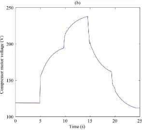
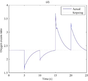
(16) List of Figures Figure 1.1 Schematic of components and working principle of a cell in PEMFC stack……4 Figure 1.2 Exploded view of a basic unit of a PEMFC stack……………………………….5 Figure 1.3 External view of a PEMFC stack……………………………………………......5 Figure 2.1 SIMULINK Library Browser…………………………………......……………36 Figure 2.2 Connection of blocks…………………………………………………...………36 Figure 2.3 Configuration signal attribute dialogue box……………………………………37 Figure 2.4 Configuration solver parameters dialogue box…………………………………37 Figure 2.5 Linear SVM regression…………………………………………………………41 Figure 2.6 Nonlinear SVM regression……………………………………………………..44 Figure 2.7 PEMFC system showing inputs and outputs…..…….………………………....47 Figure 2.8 MIMO SVM modelling framework……………………………….…………...49 Figure 2.9 Input excitation and output response signals: (a) Stack current………….…….49 Figure 2.9 Input excitation and output response signals: (b) Compressor motor voltage....50 Figure 2.9 Input excitation and output response signals: (c) Stack voltage………….……50 Figure 2.9 Input excitation and output response signals: (d) Oxygen excess ratio……..…51 Figure 2.10 Performance of the SVM model for stack voltage: (a) Training output….......55 Figure 2.10 Performance of the SVM model for stack voltage: (b) Training error……......55 Figure 2.10 Performance of the SVM model for stack voltage: (c) Testing output…….....56 Figure 2.10 Performance of the SVM model for stack voltage: (d) Testing error………....56 Figure 2.11 Performance of the SVM model for oxygen excess ratio: (a) Training output.57 Figure 2.11 Performance of the SVM model for oxygen excess ratio: (b) Training error...57 Figure 2.11 Performance of the SVM model for oxygen excess ratio: (c) Testing output..58 Figure 2.11 Performance of the SVM model for oxygen excess ratio: (d) Testing error….58 Figure 2.12 Schematic of the combined empirical and mechanistic model………..……...64 xiv.
(17) Figure 2.13 Block diagram of V0 implemented in SIMULINK……………….…..………67 Figure 2.14 Input excitation and output response signals of V0: (a) Current………….…...68 Figure 2.14 Input excitation and output response signals of V0: (b) Temperature….….......68 Figure 2.14 Input excitation and output response signals of V0: (c) Voltage….….....…….69 Figure 2.15 Training and testing results of the SVM model for V0: (a) Training output….71 Figure 2.15 Training and testing results of the SVM model for V0: (b) Training error……71 Figure 2.15 Training and testing results of the SVM model for V0: (c) Testing output…...72 Figure 2.15 Training and testing results of the SVM model for V0: (d) Testing error….….72 Figure 2.16 Characterization of Ballard MK5-E PEMFC stack…....….…….…………….73 Figure 2.17 Experimental data and empirical submodel.…….……….…….……………...74 Figure 3.1 Principle of model predictive control….….….….….….….….….….….….…..96 Figure 3.2 Schematic of the PEMFC system and the controller….….….….….….….……99 Figure 3.3 PEMFC control system implemented in SIMULINK….….….….….….…….100 Figure 3.4 Performance of the MPC: (a) Stack current….….….….….….….….….….…102 Figure 3.4 Performance of the MPC: (b) Compressor motor voltage.….….….….………103 Figure 3.4 Performance of the MPC: (c) Stack voltage.….….….….………….…………103 Figure 3.4 Performance of the MPC: (d) Oxygen excess ratio….….….…………………104 Figure 3.5 Schematic of velocity updating in PSO.….…………….…….….………...….103 Figure 3.6 Schematic of the proposed MPC integrated with PSO….…….….………...…109 Figure 3.7 Flowchart of the PSO algorithm.…….….……….….…….….……….………110 Figure 3.8 Performance of the proposed MPC: (a) static scenario….….………….….….112 Figure 3.8 Performance of the proposed MPC: (b) dynamic scenario….….………….….112 Figure 3.9 Framework of the constrained MPC….….………….….….………….….…...113 Figure 3.10 Flow chart of the modified PSO for the constrained MPC.………….….…...117 Figure 3.11 Performance of the constrained MPC: (a) Current………….….…................119 xv.
(18) Figure 3.11 Performance of the constrained MPC: (b) Voltage……….….…...................120 Figure 3.11 Performance of the constrained MPC: (c) Oxygen flowrate. ……….….…...120 Figure 3.11 Performance of the constrained MPC: (d) Hydrogen flowrate…….….…….121 Figure 3.11 Performance of the constrained MPC: (e) Oxygen partial pressure…………121 Figure 3.11 Performance of the constrained MPC: (f) Hydrogen partial pressure……….122 Figure 3.11 Performance of the constrained MPC: (g) Pressure difference.……………..122 Figure 3.11 Performance of the constrained MPC: (h) Excessive oxygen……………….123 Figure 3.11 Performance of the constrained MPC: (i) Excessive hydrogen……………..123 Figure 4.1 Components and volumes in PEMFC reactant supply system………………..133 Figure 4.2 Efficiency curves of PEMFC under different operating conditions…………..140 Figure 4.3 Schematic of the MEPT control system………………………………………145 Figure 4.4 Performance of the MEPT controller: (a) Stack current……………………...150 Figure 4.4 Performance of the MEPT controller: (b) Efficiency…………………….…...150 Figure 4.4 Performance of the MEPT controller: (c) Compressor motor voltage………..151 Figure 4.4 Performance of the MEPT controller: (d) Oxygen excess ratio………….…...151 Figure 4.4 Performance of the MEPT controller: (e) Efficiency vs. oxygen excess ratio..152 Figure 4.5 Response of PEMFC without controller: (a) Efficiency……….…..……….....152 Figure 4.5 Response of PEMFC without controller: (b) Oxygen excess ratio…….……...153 Figure 4.6 Response of PEMFC with Pukrusphan‘s controller: (a) Efficiency…………..153 Figure 4.6 Response of PEMFC with Pukrusphan‘s controller: (b) Compressor motor voltage…………………………………………………………………………………….154 Figure 4.6 Response of PEMFC with Pukrusphan‘s controller: (c) Oxygen excess ratio..154 Figure 5.1 Thermal model validation: (a) Experimental data and thermal model………..172 Figure 5.1 Thermal model validation: (b) Relative error………………………..………..172 Figure 5.2 Schematic of PEMFC thermal system implemented in SIMULINK…………175 Figure 5.3 Performance of the proposed thermal controller: (a) Stack current…………..177 xvi.
(19) Figure 5.3 Performance of the proposed thermal controller: (b) Coolant flux…………...177 Figure 5.3 Performance of the proposed thermal controller: (c) Stack temperature……..178 Figure 5.3 Performance of the proposed thermal controller: (d) Coolant temperature…..178 Figure 6.1 Distribution of population and major cities in China………..………..……....187 Figure 6.2 China‘s energy consumption by fuel in 2000 and 2010…..…….…..………....188 Figure 6.3 China‘s energy consumption by sector in 2009..………..……..….……..…….189 Figure 6.4 China‘s crude oil imports by source in 2010……..……..….……..….………..191 Figure 6.5 Location of major coal resources in China…..….……..….……..….……..…..196 Figure 6.6 Location of major oil resources in China.….……...….……..….….……..……198 Figure 6.7 Major natural gas field and infrastructure in China……...….……..……………200 Figure 6.8 China's annual average winder power……...….……..………………………...203 Figure 6.9 Distribution of China‘s solar resources…...….……..…………………...…...…204 Figure 6.10 Number of projects on hydrogen and fuel cell supported by NSFC…………..208. xvii.
(20) List of Publications The publications in this list were written during the PhD candidature and include the research results.. Peer-Reviewed Journal Publications Jun Lu, Ahmad Zahedi, ― Air supply control for maximum efficiency point tracking in Fuel cell systems,‖ Journal of Renewable and Sustainable Energy, vol. 4, paper no. 033106, pp. 1-15, 2012. (Impact Factor 1.214) Jun Lu, Ahmad Zahedi, ― Constrained model predictive control of PEMFC based on a combined empirical and mechanistic model,‖ Journal of Renewable and Sustainable Energy, vol. 4, paper no. 53116, pp. 1-15, 2012. (Impact Factor 1.214) Jun Lu, Ahmad Zahedi, ― Building the hydrogen economy in China: drivers, resources and technologies,‖ Renewable and Sustainable Energy Reviews, vol. 23, pp. 543-556, 2013. (Impact Factor 6.018) Jun Lu, Ahmad Zahedi, ― Thermal modelling and management of proton exchange membrane fuel cell,‖ Energy Sources, Part A Recovery, Utilization and Environmental Effects, in press. (Impact Factor 0.715). xviii.
(21) Peer-Reviewed Conference Publications Jun Lu, Ahmad Zahedi, ― Maximum efficiency point tracking control for fuel cell power systems,‖ in Proceedings of 2010 International Conference on Power system Technology, pp. 1-6, 2010. Modelling and control of PEMFC based on support vector Jun Lu, Ahmad Zahedi, ― machine,‖ in Proceedings of 2011 Australasian Universities Power Engineering Conference, pp. 1-6, 2011. Jun Lu, Ahmad Zahedi, ― Model predictive control for PEMFC based on least square support vector machine,‖ in Proceedings of 2012 Asia-Pacific Power and Energy Engineering Conference, pp. 1-4, 2012. Support vector machine based predictive controller with swarm Jun Lu, Ahmad Zahedi, ― intelligence for PEMFC,‖ in Proceedings of 2012 Australasian Universities Power Engineering Conference, pp. 1-6, 2012. Jun Lu, Ahmad Zahedi, ― Predictive control of PEMFC based on a combined empirical and mechanistic model,‖ in Proceedings of 2012 International Conference on Power system Technology, pp. 1-6, 2012. Ahmad Zahedi, Jun Lu, ― Economic evaluation of grid-connected solar PV production cost in New Zealand,‖ in Proceedings of 2012 International Conference on Power system Technology, pp. 1-4, 2012.. xix.
(22) Chapter 1 Introduction 1.1 Overview of fuel cells Fuel cells are electrochemical devices that convert the chemical energy of a reaction directly into electrical energy. In a typical fuel cell, fuel (hydrogen, methanol, natural gas, etc) is fed continuously to the anode (negative electrode) and an oxidant (often oxygen from air) is fed continuously to the cathode (positive electrode). The electrochemical reactions take place at the electrodes to produce an electric current through the electrolyte, while driving a complementary electric current that performs work on the load. As opposed to a battery wherein the chemical reactants are exhausted, the fuel cell is an energy conversion device which can theoretically produce energy so long as the fuel/oxidant supply to the electrodes is maintained. In addition, fuel cells produce electrical energy directly from chemical energy. As a result, fuel cells are not limited by the thermodynamic limitation of conventional heat engines, such as the Carnot cycle efficiency. Since NASA first adopted fuel cell systems as the electric power generating units for their spacecrafts in the 1950s~1960s, fuel cells have sparked much interest and activity as alternative power generators [1]. Fuel cells are classified into six types based on the type of electrolyte: proton exchange membrane fuel cell (PEMFC), direct methanol fuel cell (DMFC), alkaline fuel cell (AFC), phosphoric acid fuel cell (PAFC), molten carbonate fuel cell (MCFC), and solid oxide fuel cell (SOFC). The type of electrolyte determines the electrode reactions and the type of ions that carry the current across the electrolyte. In addition, the choice of electrolyte dictates the operating temperature range of the fuel cell. Aqueous electrolytes are limited to 1.
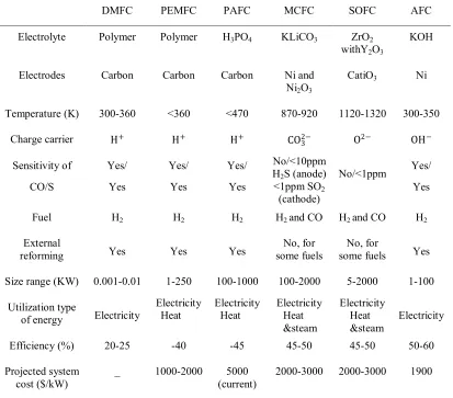
(23) temperatures of about 200 °C or lower because of their high vapor pressure and rapid degradation at higher temperatures. The operating temperature also plays an important role in dictating the degree of fuel processing required. In low-temperature fuel cells, all the fuel must be converted to hydrogen prior to entering the fuel cell. In addition, the anode catalyst in low temperature fuel cells (mainly platinum) is strongly poisoned by CO. In high-temperature fuel cells, CO and even CH4 can be internally converted to hydrogen or even directly oxidized electrochemically. Table 1.1 provides an overview of the key characteristics of the main fuel cell types, while major advantages and disadvantages of each fuel cell type are summarized in Table 1.2 [2] [3]. Table 1.1 Key characteristics of the main fuel cell types DMFC. PEMFC. PAFC. MCFC. SOFC. AFC. Electrolyte. Polymer. Polymer. H3PO4. KLiCO3. ZrO2 withY2O3. KOH. Electrodes. Carbon. Carbon. Carbon. Ni and Ni2O3. CatiO3. Ni. Temperature (K). 300-360. <360. <470. 870-920. 1120-1320. 300-350. Charge carrier. H+. H+. H+. CO2− 3. O2−. OH −. Sensitivity of. Yes/. Yes/. Yes/. CO/S. Yes. Yes. Yes. No/<10ppm H2S (anode) <1ppm SO2 (cathode). Fuel. H2. H2. H2. H2 and CO. H2 and CO. H2. External reforming. Yes. Yes. Yes. No, for some fuels. No, for some fuels. Yes. Size range (KW). 0.001-0.01. 1-250. 100-1000. 100-2000. 5-2000. 1-100. Utilization type of energy. Electricity. Electricity Heat. Electricity Heat. Electricity Heat &steam. Electricity Heat &steam. Electricity. Efficiency (%). 20-25. -40. -45. 45-50. 45-50. 50-60. Projected system cost ($/kW). _. 1000-2000. 5000 (current). 2000-3000. 2000-3000. 1900. 2. No/<1ppm. Yes/ Yes.
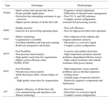
(24) Table 1.2 Advantages and disadvantages of the main fuel cell types Type PEMFC. DMFC. PAFC. MCFC. SOFC. AFC. Advantages. Disadvantages. - Quick system start-up and shut down - Proper portable applications - Electrolyte has outstanding resistance to gas crossover - Highest power density of all the fuel cells. - Expansive catalyst (platinum) - Difficulties in thermal/water management - Poor CO, S, and NH3 tolerance - Complex system configuration (external fuel processing system). - Simple structure - Good for low power/long operating hours. - Poor cell efficiency - Poor for high power/short term operation. - Mature technology - Cogeneration is available - Excellent reliability and long-term running - Relatively inexpensive electrolyte. - Slow reduction in the cathode side (requires platinum catalyst) - Electrolyte is a corrosive liquid - Complex system configuration. - Fuel flexibility - Non-precious metal catalyst - High quality waste heat for cogeneration - Higher system efficiency than PEMFC/PAFC. - Corrosive and mobile electrolyte - High temperature promotes material problems (degradation/lifetime issues) - High contact resistance and cathode resistance limit power density. - Fuel flexibility - Non-precious metal catalyst - Solid electrolytes allow various shapes of cell - High quality waste heat for cogeneration. - High temperature causes material problems such as thermal expansion - Sealing issues - Limited range of material selection - Relatively expansive components and Fabrication. - Highest efficiency of all the fuel cells - Low manufacturing and operation costs - Mature technology. - Poor CO2 tolerance - Electrolyte is a corrosive liquid - Complex system configuration. 1.2 Overview of proton exchange membrane fuel cell Since the first application of PEMFC systems was initially reported in the New Generation of Vehicles program (PNGV) in the US in 1993 [4], PEMFC research has been attracting increasing attention worldwide. PEMFC has shown great potential for transportation application due to its many advantages, such as long stack life, high power density, low operating temperature, fast start-up, suitability for discontinuous operation [5-8]. In addition, a hydrogen-powered PEMFC does only emit water with no carbon dioxide or other pollutants. 3.
(25) Figure 1.1 shows the schematic of components and working principle of a single cell in the PEMFC stack. As can be seen, cathode (positive electrode) and anode (negative electrode) are separated by electrolyte (e.g., a polymer membrane). Each electrode is made up of a thin catalyst layer (CL) which contains the electro-catalyst, and a porous gas diffusion layer (GDL). The GDL, in addition to serving as a mechanical support for the thin catalyst layer, allows for the diffusion of the reactant gases to, and removal of products from the catalyst sites. The membrane and the electrodes together are commonly referred to as the membrane electrode assembly (MEA). Now, consider the working principle of PEMFC. On the cathode side, oxygen diffuses through the GDL towards the electrolyte and is reduced, while hydrogen is oxidized on the anode side. The migration ion H+ forms at the anode and carries the charge through the proton exchange membrane towards the cathode side. On the other hand, the electrons pass through the current collectors into an external circuit towards the cathode, and water is produced on the cathode side. An electrical circuit is created by the ion transfer through the electrolyte and the electron transfer through the external circuit.. Figure 1.1 Schematic of components and working principle of a cell in PEMFC stack. 4.
(26) The bipolar plate (interconnector) is used for separating the cells in a stack, connecting them electrically in series, and providing flow channels (see Figure 1.2). In addition, some of the flow channels on the plate may act as cooling channel for the purpose of thermally management in the stack. The stack is connected to an external circuit via a current collector (see Figure 1.3). The reactants are supplied to the electrodes using the manifolds.. Figure 1.2 Exploded view of a basic unit of a PEMFC stack. Figure 1.3 External view of a PEMFC stack. 5.
(27) 1.3 Scope of the thesis This thesis addresses four major themes regarding the development of PEMFC: (1) modelling, (2) control, (3) maximum efficiency point tracking (MEPT), (4) thermal modelling and management. In addition, key issues of building hydrogen economy in China, including drivers, resources and technologies, are reviewed. The significance of these problems is briefly explained in the following section. One of the most important aspects in developing PEMFC is the mathematical modeling. The mathematical model serves as an indispensible tool for studying static and dynamic behaviour of PEMFC, designing the cells, evaluating control strategies and designing experiments; it helps reduce the number of experimental tests required to study the cells systematically [9]. Simulation studies can determine the effects of various operating conditions on the performance of PEMFC. Therefore, modelling is considered as the first priority and discussed in Chapter 2. Another fundamental aspect in developing PEMFC is the control strategy. The basic control goals of PEMFC are: (a) maintaining the output voltage when variations in operating conditions occur, (b) supplying the required power in the presence of rapid variations in the external loads. Another control problem particularly for PEMFC is the phenomenon of oxygen starvation, which may occur when there is a sudden large increase in the load power. In this case, the partial pressure of oxygen drops significantly, accompanied by a rapid decrease in cell voltage, which in turn shortens the life of PEMFC [9]. Therefore, a proper controller is required to effectively prevent oxygen starvation. To achieve these objectives, a series of control strategies are designed and tested in Chapter 3.. 6.
(28) The core factor that affects its commercialization potential is the cost of electricity provided by PEMFC system. The cost of electricity is determined by the capital cost of the PEMFC system, the cost of fuel and the efficiency of the whole system. The PEMFC system that always operates at the maximum efficiency produces the least expensive electricity. As a result, the ability to increase the operational efficiency is a crucial issue for the design of a cost-effective fuel cell system with high market competitiveness [10]. Therefore, the maximum efficiency point tracking of PEMFC system is discussed in chapter 4. Thermal management is crucial for the safe operation of PEMFC as current PEMFC operates in a narrow temperature range of 60–80°C and tolerates only a small temperature variation [11]. This range is dictated by the material properties of the proton exchange membrane, most commonly Nafion. Abnormal operating temperature may devastate the performance or even cause permanent damage to the cell. Therefore, thermal study is conducted in Chapter 5. As an emerging giant of the world economy and international energy markets, China is transforming the global energy system by dint of its sheer size and its growing weight in international energy trade. How rapidly China‘s energy needs develop and how they are met will have far-reaching consequences for the rest of the world. The major concern for improving energy security and reducing greenhouse gas emissions, together with the rapid development of fuel cell technologies in recent years, is focusing China‘s opinion on options for future hydrogen economy. As such, Chapter 6 reviews drivers, resources, and technologies for building the hydrogen economy in China. The results will help us understand China‘s energy system and its impact on global environment and energy trade.. 7.
(29) 1.4 Challenges and objectives 1.4.1 Modelling The PEMFC system is a complex system with highly coupled electrochemical, thermodynamics and fluid dynamics. Especially, PEMFC system‘s inherent nonlinearities, time-varying properties and tight operating constraints give rise to great challenges for system modelling [12]. These characteristics make traditional linearization-based models and control methods only valid in the neighborhood of the optimal operating point. In real world applications, however, PEMFC does not usually operate at the optimal steady-state designed by the fuel cell manufacturer [13]. The operating point of PEMFC may change frequently over a wide operating range due to the fluctuating power demands or varying operating conditions. Therefore, novel nonlinear modelling and control method must be employed. Models of PEMFC in the literature can be classified into two categories: mechanistic models and empirical models. Mechanistic models refer to those using basic physical or electrochemical equations for investigating the details of operation in PEMFC. These models usually have very complicated expression with some key physical parameters that are even immeasurable. In addition, these models require iterative methods to solve the underlying differential and partial differential equations, thereby making them computationally intensive. In essence, mechanistic models are suited for the design and optimization of the cell components, rather than for control purpose. On the other hand, empirical models behave like a black box, focusing only on input-output relationship. These models allow quick prediction of the PEMFC‘s performance given operating conditions, which lays down a solid foundation for the 8.
(30) real-time calculation of the control algorithm. From this perspective, empirical models are more suitable for control study. Based on the discussion above, it can be concluded that empirical model is the better choice for this research due to the requirement of control study. Accordingly, the specific objectives for developing the empirical model of PEMFC are to: . Acquire PEMFC operation data including manipulated inputs, disturbance inputs and performance outputs.. . Develop the empirical model of PEMFC with the operation data. Pre-processing of the raw data may be required.. . Validate the performance of the proposed empirical model. A performance comparison between the novel empirical model and the conventional model is preferred.. 1.4.2 Control As with modelling, the major barriers for the control strategy are PEMFC‘s nonlinearities and time-varying properties. One approach to circumvent these problems is investigating the system in real time. Thus, time-dependent parameters can be more readily tracked and a model structure can be more accurately estimated. Model predictive control (MPC), characterized by its receding horizon strategy, is the one employing such method. The basic idea of receding horizon strategy involves real-time estimation of system states and solution of the control problem for the given state; the first part of the resulting input signal is implemented and the whole process is repeated. 9.
(31) In addition, the tight operating constraint of PEMFC also poses challenges for the controller design. In PEMFC system, several constraints must be respected. First of all, the supply of sufficient hydrogen and air must be ensured at all times. Moreover, the hydrogen and air supply must be coordinated in a way that the pressure difference across the fuel cell membrane is small to avoid membrane damage. In other words, the partial pressure difference between oxygen and hydrogen should be maintained in a safe range. On the other hand, a major advantage of MPC over other control schemes is its ability of handling constraints in a systematic and straightforward manner [14]. This is because that the MPC formulates the control problem as the optimization of an objective function. By employing a proper optimization algorithm, the resulting constrained optimization problem can be effectively solved. To summarize, MPC has great potential to handle PEMFC‘s inherent nonlinearities, time-varying characteristics and tight operating constraints. Accordingly, the specific objectives for developing MPC strategy are to: . Design the MPC strategy based on the PEMFC empirical model developed previously.. . Select an efficient optimization algorithm to solve the optimization problem formulated by MPC. Modification of the optimization algorithm may be required to handle the constraints.. . Test the performance of the proposed MPC strategy. Both static scenario and dynamic scenario must be considered.. 10.
(32) 1.4.3 Maximum efficiency point tracking The efficiency of the fuel cell system nonlinearly depends on various operating conditions. Among them, the air flow supplied to the fuel cell system is one of the most significant factors in determining the efficiency. The conventional method of controlling the air flow is to stabilize the oxygen supply at a predetermined constant rate for the optimal efficiency. However, in practice, the optimal point can deviate from the pre-set value due to the varying operating conditions, such as the uncontrollable load [15]. Therefore, the major barrier of achieving maximum operating efficiency lies in the real-time estimation of the optimal air supply level. Moreover, sufficient air supply must be ensured at all time to prevent oxygen starvation. As a result, a maximum efficient point tracking (MEPT) controller is required for estimating and tracking the time-varying maximum efficient point. Accordingly, the specific objectives are to: . Analyse the efficiency of PEMFC under various operation conditions and obtaining the efficiency curves with peaks indentified.. . Design the MEPT controller that can handle the time-varying maximum efficient point.. . Validate the performance of the proposed MEPT controller. The result must be compared with that of steady-state efficiency analysis.. 1.4.4 Thermal modelling and management Despite a large number of publications on thermal modelling of PEMFC, models suitable for thermal management are still lacking. Most existing models are mechanistic models, 11.
(33) ranging from one dimensional non-isothermal models [16] to three dimensional non-isothermal models [17], [18]. These models are developed for investigating the temperature distribution within the cell, rather than for temperature control. As a result, the first barrier is the lack of a control-oriented thermal model of PEMFC. On top of that, a temperature controller that can handle the nonlinearities and disturbances is required. Accordingly, the specific objectives are to: . Develop a control-oriented thermal model of PEMFC. . Design a thermal controller that can handle the nonlinearities and disturbances. . Validate the performance of the proposed thermal model and controller. 1.4.5 Building the hydrogen economy in China China is unique in terms of its vast area, huge population and rapid economic growth. These situations provide both opportunities and challenges for the transition towards the hydrogen economy. In order to clarify a clear vision of future hydrogen economy in China, three factors that should be paid special attention to are: drivers, resources and technologies. Accordingly, the specific objectives are to: . Identify China‘s main drivers for the transition towards the hydrogen economy. . Review China‘s energy supply matrix and analysing the potential role of different energy resources in future hydrogen economy. 12.
(34) . Review China‘s policy and government support programs for the R&D of hydrogen and fuel cell technologies. Research achievements are also required to be summarized.. 1.5 Organization of the thesis In Chapter 2, the modelling of PEMFC is discussed. First, the major concerns in the development of PEMFC models are summarized and some of the most representative examples of PEMFC models in the literature are reviewed. Then, the theory of support vector machine (SVM) is briefly introduced and the empirical model of PEMFC is developed using SVM. Finally, the combined empirical and mechanistic model is proposed. In Chapter 3, the control of PEMFC is addressed. First, a literature review on PEMFC control strategy is conducted. Then, the principle of MPC is briefly reviewed and the model predictive controller for PEMFC is designed. Next, the theory of particle swarm optimization (PSO) is introduced and the novel MPC strategy is designed based on the particle swarm optimizer. Finally, the constrained MPC strategy is designed based on the combined model developed previously. The standard PSO algorithm is modified to solve the constrained optimization problem formulated by MPC. In Chapter 4, the maximum efficiency point tacking problem is formulated and a MEPT controller is designed. First, the steady-state efficiency analysis is conducted and efficiency curves under different operating conditions are obtained. Then, the theory of extremum seeking control (ESC) is introduced and the MEPT controller is designed based on extremum seeking control algorithm. Finally, the whole system is simulated and results are discussed. 13.
(35) In Chapter 5, the thermal management of PEMFC is discussed. First, general issues of thermal management in PEMFC are analyzed and the existing thermal models and control methods are reviewed. Then, the control-oriented thermal model of PEMFC is developed and the model-based thermal controller is designed. Finally, the whole system is simulated and results are discussed. In Chapter 6, key issues concerning China‘s transition towards hydrogen economy are reviewed. First, a brief presentation of China‘s geographic and economic data, together with its energy consumption profile, is given. Then, China‘s main drivers for the hydrogen economy are discussed. A section on China‘s energy supply matrix and potential sources for hydrogen production follows. Finally, the interests in hydrogen and fuel cell technologies within China are reviewed. Chapter 7 summarizes the major contributions of this thesis and presents the conclusions. Future work is also suggested.. 14.
(36) References [1] J. M. Andujar, F. Segura, "Fuel cells: history and updating. A walk along two centuries," Renewable Sustainable Energy Rev., vol.13, pp. 2309-2322, 2009. [2] National Energy Technology Laboratory, U.S. Department of Energy, Fuel Cell Handbook, University Press of the Pacific, 2005. [3] R. O‘Hayre, S. Cha, W. Colella, F. Prinz, Fuel Cell Fundamentals, New York: Wiley, 2006. Quantum jumps in the PEMFC science and technology [4] P. Costamagna, S. Srinivasan, ― from the 1960s to the year 2000 Part I. Fundamental scientific aspects.‖ J. Power Sources, vol. 102, pp. 242–252, 2001. [5] P. Costamagna, S. Srinivasan, ― Quantum jumps in the PEMFC science and technology from the 1960s to the year 2000 Part II. Engineering, technology, development and application aspects,‖ J. Power Sources, vol. 102, pp. 253–269, 2001. [6] S. G. Chalk, J. F. Miller, F. W. Wagner, ― Challenges for fuel cells in transport applications,‖ J. Power Sources, vol. 86, pp. 40–51, 2000. Review and analysis of PEM fuel cell design and [7] V. Mehta, J. S. Cooper, ― manufacturing,‖ J. Power Sources, vol. 114, pp. 32–53, 2003. [8] S. Gamburzev, A. J. Appleby, ― Recent progress in performance improvement of the proton exchange membrane fuel cell (PEMFC),‖ J. Power Sources, vol. 107, pp. 5–12, 2002. [9] M Bavarian, M Soroush, I. G. Kevrekidis, J. B. Benziger, ― Mathematical modeling, steady-state and dynamic behavior, and control of fuel cells - a review,‖ Ind. Eng. Chem. Res., vol. 49, pp. 7922–7950, 2010. 15.
(37) [10] W. Na and B. Gou, "The efficient and economic design of pem fuel cell systems by multi-objective optimization," J. Power Sources, vol.166, pp. 411-418, 2007. [11] S. G. Kandlikar, Z Lu, ― Thermal management issues in a PEMFC stack - A brief review of current status,‖ Appl. Therm. Eng., vol.29, pp. 1276-1280, 2009. [12] J. G. Williams, G. Liu, S. Chai, and D. Rees, "Intelligent control for improvements in PEM fuel cell flow performance," Int. J. Autom. Comput., vol. 5, pp. 145-151, 2008. [13] J. Golbert, and D. R. Lewin, "Model-based control of fuel cells (1): Regulatory control," J. Power Sources, vol. 135, pp. 135-151, 2004. [14] L. Wang, F. Wan "Structured neural networks for constrained model predictive control." Automatica, vol. 37, pp. 1235–1243, 2001. Maximum Efficiency Point Tracking [15] M. Jang, J. Lee, J. Kim, J. Park, B. Cho, ― Algorithm Using Oxygen Access Ratio Control for Fuel Cell Systems,‖ J. Power Electron., vol. 11, pp. 194-201, 2011. [16] M. Wohr, K. Holwin, W. Schurnberger,. M. Fischer, W. Neubrnad, G. Eigenberger,. ―D ynamic modeling and simulation of a polymer membrane fuel cell including mass transport limitation,‖ Int. J. Hydrogen Energy, vol. 23, pp. 213-218, 1998. [17] T. Berning, N. Djilali, ― Three-dimensional computational analysis of transport phenomena in a PEM fuel cell—a parametric study,‖ J. Power Sources, vol. 124, pp. 440-452, 2003. [18] T. Berning, D.M. Lu, N. Djilali,. ― Three-dimensional computational analysis of. transport phenomena in a PEM fuel cell,‖ J. Power Sources, vol. 106, pp.284-294, 2002.. 16.
(38) Chapter 2 Modelling Mathematical modeling is an indispensable tool for studying static and dynamic behavior of fuel cells, optimizing the design of the cell and evaluating control strategies. With the help of mathematical models, the number of experimental tests required can be reduced to a large extent. Through simulation studies, one can easily understand the effects of various operating conditions, cell temperature distribution or thermal stresses, etc. As such, modelling of PEMFC has received much attention over the last decade. The major contributions of Chapter 2 includes: (1) The novel empirical models of PEMFC are developed using support vector machine (SVM). SVM is a nonlinear generalization algorithm, which learns from experimental data to establish input-output relationship through regression analysis. The SVM models of PEMFC map the performance outputs as a function of various operation conditions and predict future output without the knowledge of internal details. (2) The hybrid modelling approach is proposed based on the combination of prior knowledge, under the form of mechanistic submodel, with empirical submodel devoted to the extraction of knowledge from operating data. The empirical submodel is a SVM model, which predicts cell voltage at different stack currents and temperatures under the reference hydrogen and oxygen partial pressure. The mechanistic submodel calculates the correction voltage by taking account of hydrogen and oxygen partial pressure changes. The chapter is organized as follows:. In section 2.1, the major concerns in the. development of PEMFC models are summarized. In section 2.2, some of the most representative examples of PMEFC models in the literature are reviewed. In section 2.3, support vector machine is introduced for the modelling of PEMFC. In section 2.4, empirical 17.
(39) models of PEMFC are developed using SVM. In section 2.5, the combined empirical and mechanistic model of PEMFC is proposed.. 2.1 General features of PEMFC models Over the past decades, a great number of PEMFC models have been developed with different features and focuses. As the optimal model choice differs for each application and user, it is necessary to clarify what the key features of the desired model are before developing models. Although vital for the result, these initial criteria often tend to be overlooked [1]. Table 2.1 summarizes the key features of PEMFC models.. Table 2.1 Key features of PEMFC system model Approach (mechanistic, empirical) State (steady-state, transient) Boundary (cell, stack, system) Dimension (0D,1D,2D,3D) Phenomena to Take into Account. . Approach. The first criterion in the table is modelling approach. A PEMFC model may fall into one of two categories: mechanistic or empirical. A mechanistic (or called ― theoretical‖) model is based on in-depth knowledge of the electrochemistry, heat transfer and mass transfer involved in the fuel cell, using basic, phenomenological equations such as the Butler-Volmer equation for cell voltage, the Stefan-Maxwell equation for gas-phase 18.
(40) transport, and the Nernst-Planck equation for species transport. Depending on its focus, the model explain the fundamental processes occurring in the fuel cell, such as cell flow pattern, current density distribution, voltage and pressure drops. However, these models usually require iterative methods to solve the underlying differential and partial differential equations, which makes them computationally intensive. Besides, given the highly reactive environment within the fuel cell, it is often impossible to measure critical parameters, such as temperature, pressure and potential gradients, or species concentration within the cell. Thus, the validation of these models is extremely difficult to achieve. In essence, the mechanistic models are suited for design and optimization of cell components, rather than for control purpose. On the other hand, empirical models are based on experimental data specific to each application and operating condition. Empirical relationships are employed when the physical phenomena are difficult to model or the theory governing the phenomena is not well understood. As empirical models typically do not provide as many details as mechanistic models do and already, at least to some extent, are validated, they may provide a fast start into fuel cell modeling and a good basis for engineering applications. These models allow engineers to make quick prediction of the PEMFC‘s performance given operating conditions. This is of significant benefits for the control study. However, empirical models are limited to a specific application or a narrow corridor of operating conditions. They cannot be used to predict the performance of innovative designs, or the response of the fuel cell to parameter changes outside of the conditions under which the empirical relationships were developed. Empirical relationships also do not provide an adequate physical understanding of the phenomena inside the cell. They only correlate outputs with inputs. 19.
(41) However, it is worth pointing out that there is no sharp distinction between mechanistic and empirical models; for instance, a PEMFC system model may use a more mechanistic approach to model the fuel cell and empirical maps of compressors and other devices in the system. . State. With respect to temporal changes, the system can be studied at steady-state or transient conditions. Steady-state models describe the behavior of PEMFC based on one operating point in each step. The main purposes of steady-state models are to design the fuel cell components and to choose the fuel cell operating points. However, unsteady-state behaviour is also an important issue, especially for the transportation application of PEMFC, where the operating conditions constantly change. Transient models are used to predict the performance of PEMFC as a function of time under varying operating conditions. . Boundary. The system boundary defines the area of interest of the model. It could be on the fundamental cell level including the electrodes and the membrane, the high level with individual fuel cells assembled in a fuel cell stack or the higher level with fuel cell system consisting of a fuel cell stack and its auxiliary system of compressor, pumps, and so forth. . Dimension. With respect to spatial changes, the problem can be zero-dimensional (lumped model), one-dimensional (D), two-D, or three-D, depending on the number of spatial independent variables of the resulting model (differential equations). 20.
(42) . Phenomena to Take into Account. PEMFC is a multidisciplinary area. Electrochemical, fluid/thermal dynamics and transport phenomena are all involved within a cell. Mass, momentum, species, charge, and energy conservation principles provide the fundamental governing equations. Depending on its focus, the PEMFC model usually accounts for specific phenomena.. 2.2 Literature review of PEMFC models This section presents a review of the most representative examples of PEMFC models, ranging from 0D to 3D models. A summary of the PEMFC models reviewed is given in Table 2.2. . 0D models (lumped models). The simplest approach to dynamic modeling fuel cells is to ignore spatial changes and to consider changes with time only. A great number of studies considering lumped-parameter models for PEMFC can be found in the literature. Some influential lumped models are reviewed as follows. Amphlett et al. [2] developed a steady-state model to study the transient behavior of PEMFC. This model accounted for activation and ohmic overvoltage. The power output of the PEMFC stack was calculated from the current, stack temperature, hydrogen and oxygen gas flow rates, and partial pressures. The model was used to predict transient response of the cell during start-up, load changes and shut-down. Pukrushpan [3] developed a transient model of PEMFC for the control study. The transient phenomena captured in the model include the flow characteristics and inertia 21.
(43) dynamics of the compressor, the manifold filling dynamics, and consequently, the reactant partial pressures. Unlike other system models existing in the literature where a single polarization curve or a set of polarization curves for different cathode pressure was used, the fuel cell polarization curve used in this model was a function of oxygen and hydrogen partial pressures and membrane water content. Yerramalla et al. [4] proposed a linear as well as a nonlinear dynamic model of PEMFC. The model accounted for energy and mass transfer, as well as electrochemical reactions and the inverter load. The voltage response predicted by the model was in the form of a ripple for varying loads, which implied that an effective controller was required when there were rapid fluctuations in the load. Xue et al. [5] developed a system level lumped-parameter model of PEMFC for investigating the the mixed effects of temperature, gas flow, and capacitance, with particular emphasis focused on system transient behavior. The PEMFC system was divided into three control volumes and thus a lumped-parameter model for each control volume was derived. Simulation results revealed that complicated dynamic interactions existed among various components and mechanisms within the PEMFC system. Pathapati et al. [6] developed a PEMFC dynamic model that incorporated the effects of charge double layer capacitance, the dynamics of flow and pressure in the anode and cathode channels, as well as mass/heat transfer transient features in the fuel cell body. The model was used to study the transient response of cell voltage, cell temperature, hydrogen /oxygen outlet flow rates, and anode and cathode channel temperatures and pressures to a. 22.
(44) step change in the load. Simulation results were in good agreement with data from laboratory experiments. Benziger et al. [7] introduced a new PEMFC design, which was based on coupled stirred tank reactors (STRs) and a membrane. This fuel cell can be regarded as a set of reactors connected through a set of flow regulators. The gas phase in each reactor compartment was assumed to be well mixed. The STR PEMFC was one-dimensional; spatial gradients were transverse to the membrane only. A lumped parameter model was then developed to examine start-up, and dynamic responses to changes in load, temperature, and reactant flow rates. Experimental data were used to estimate several parameters of the model and validate the model. . 1D models. Bernardi and Verbrugge [8] developed a model for an ion-exchange membrane attached to a gas-fed porous electrode. The model accounted for cell polarization characteristics, water transport, and catalyst utilization. In addition, the effect of electroosmotic convection was included in the model for the first time. It was assumed that the membrane was in a fully hydrated state at all times. Nernst-Planck equation was used to describe the flux of species in the membrane-free volume and Schlogl‘s velocity equation was used for the polyelectrolyte membrane. The simulation results matched well with experimental data. It was also found that the polarization resistance resulting from the oxygen reduction reaction was important at all current densities, and that water transport by pressure difference and electric potential forces was a strong function of the cell operating conditions.. 23.
Figure
![Figure 3.1 Principle of model predictive control [21]](https://thumb-us.123doks.com/thumbv2/123dok_us/155323.32467/117.612.127.533.265.522/figure-principle-model-predictive-control.webp)
+7
![Figure 3.2 Schematic of the PEMFC system and the controller [28]](https://thumb-us.123doks.com/thumbv2/123dok_us/155323.32467/120.612.192.467.76.288/figure-schematic-pemfc-controller.webp)
![Figure 3.3 PEMFC control system implemented in SIMULINK (reproduced from [30])](https://thumb-us.123doks.com/thumbv2/123dok_us/155323.32467/121.612.211.454.141.360/figure-pemfc-control-implemented-simulink-reproduced.webp)
![Figure 3.7 Flowchart of the PSO algorithm [41]](https://thumb-us.123doks.com/thumbv2/123dok_us/155323.32467/131.612.224.429.416.618/figure-flowchart-pso-algorithm.webp)
Related documents
This PEMFC model was simulated using real inputs signals. Figure 4
8.4.2 CO 2 behavior inside parallel DMFC anode with and without dynamic contact angle effect 85 8.4.3 General process of emerging process of gas bubbles behavior in porous
Recently, Sedighzade and Fathian [12], presented a one-dimensional nonlinear state-space model for a single PEM fuel cell, which correlates changes in the cell
Control of Voltage in Proton Exchange Membrane Fuel Cell Using Model Reference Control Approach.. Hamideh Najafizadegan * ,
Improvements to the materials (cathodes, elec- trolyte and anodes) used in the polymer electrolyte membrane fuel cell (PEMFC) are required before they can be successful
However, improved stack performance must be demonstrated not only with pure hydrogen fuel but also, moreparticularly, with reformate fuel, where tolerance to poisoning by carbon
The Voltage - Current characteristics of a typical PEM fuel cell at normal air pressure and room temperature in fuel cell model losses are present which cause the cell
Even though the working of PEMWE is just the reverse of proton exchange membrane fuel cell (PEMFC), commonly used materials in PEMFC such as carbon catalyst support,
