DEVELOPMENT OF SMART LIBRARY SYSTEM USING RFID
DING YEN YEN
BACHELOR OF ELECTRICAL ENGINEERING (CONTROL, INSTRUMENTATION & AUTOMATION)
FACULTY OF ELECTRICAL ENGINEERING UNIVERSITI TEKNIKAL MALAYSIA MELAKA
“I hereby declare that I have read this project entitle “Development of Smart Library System using RFID” and that is has comply the partial fulfilment for awarding the degree of Bachelor of Electrical Engineering (Control, Instrumentation and Automation)”.
Signature : ………
Supervisor’s Name : DR. MARIAM MD.GHAZALY
I declare that this report entitle “Development of Smart Library System using RFID” is the result of my own research except as cited in the references. The report has not been accepted for any degree and is not concurrently submitted in candidature of any other degree.
Signature : ……….
Name : DING YEN YEN
ACKNOWLEDGEMENT
I would like to express my sincere gratitude to my supervisor, Dr. Mariam Md. Ghazaly for her guidance, continuous encouragement and constant support in making this research possible. I really appreciate her guidance from the initial to the final level that enabled me to develop an understanding of this research thoroughly. Without her advice and assistance it would be a lot tougher to completion. I also sincerely thanks for the time spent proofreading and correcting my mistakes.
My sincere thanks go to all lecturers and members of the staff of the Electrical Engineering Department, UTeM, who helped me in many ways and made my education journey at UTeM pleasant and unforgettable.
i
ABSTRACT
ii
ABSTRAK
iii
TABLE OF CONTENTS
CHAPTER TITLE PAGE
ABSTRACT i
ABSTRAK ii
TABLE OF CONTENTS iii
LIST OF TABLE vi
LIST OF FIGURE ix
LIST OF ABBREVIATIONS xiii
LIST OF APPENDICES xiv
1 INTRODUCTION 1
1.1 Overview 1
1.2 Introduction 1
1.3 Motivation 2
1.4 Problem Statement 3
1.5 Objective 4
1.6 Scope 5
1.7 Organization of the Project 5
2 LITERATURE REVIEW 6
iv
2.2 Project Background 6
2.3 Automatic Identification and Data Capture 7
2.3.1 Barcode 7
2.3.2 Barcode Technology Replaced by RFID 9
2.3.3 RFID Technology 9
2.3.3.1 RFID Tag 11
2.4 Automated Return System 13
2.4.1 Case Study 1: Robotic Library System 13
2.5 Object Detection System 14
2.6 Method to Control of a DC Motor 15
2.7PID Controller for DC Servo Motor 16
3 RESEARCH METHODOLOGY 20
3.1 Project Overview 20
3.2 Design A: Vertical System 23
3.3 Design B: Rotary System 25
3.4 Comparison between Design A and Design B 27
3.5 Reflection Object versus Colour 29
3.6 Effect of PWM to Motor Speed 32
3.7 Performance of RFID Reader 33
3.8 Positioning of Servo Motor 35
3.9 Coding Design and Hardware Design 37
v
4 RESULTS AND DISCUSSION 40
4.1 Overview 40
4.2 Results for Reflection Object versus Colour 40 4.2.1 Discussion for Reflection Object versus Colour 44 4.3 Results for Effect of PWM to Motor Speed 46 4.3.1 Discussion for Reflection Object versus Colour 47 4.4 Results for Performance of RFID Reader 48 4.4.1 Discussion for Performance of RFID Reader 50 4.5 Results for Positioning of Servo Motor 51
4.5.1 Discussion for Positioning of Servo Motor for No
Load Condition 54
4.5.2 Discussion for Positioning of Servo Motor for
Load Condition 62
4.6 Testing 70
4.7 Testing Problem 71
5 CONCLUSION 72
5.1 Overview 72
5.2 Conclusion and Recommendation 72
REFERENCES 73
APPENDIX 76
vi
LIST OF TABLE
TABLE TITLE PAGE
2.1 Characteristic of Barcode System and RFID System 10 2.2 Characteristic of Active Tag and Passive Tag 11
2.3 Frequency Range of RFID Passive Tag 12
2.4 Technical Specification of the Sensors 14
3.1 Gantt Chart for Final Year Project 1 20
3.2 Gantt Chart for Final Year Project 2 21
3.3 List of Experiment Setup 21
3.4 List of Design 21
3.5 Comparison between Design A and Design B 27
3.6 Shape Design for the Bookshelf 28
3.7 Components List for Hardware Design 37
4.1 Measured Data for Reflection Object versus Colour 41
4.2 Measured Data from Experiment Setup 2 46
4.3 Data Analysis for Experiment Setup 2 47
4.4 Data Collected for Position of Bookshelf
(No -Load Condition) 51
vii 4.6 Data Collected for the Position of Bookshelf
(Load Condition) 55
4.7 Data 2 56
4.8 Ziegler-Nichols Method 57
4.9 Effects of Increasing Kp (No-Load) 59
4.10 Effects of Increasing Kp (Simulated data and theoretical
Data) (No-Load) 59
4.11 Values for PI Controller based on Ziegler-Nichols Method
(No-Load) 60
4.12 Effects of Increasing Ki (No-Load) 61
4.13 Effects of Increasing Ki (Simulated data and theoretical
Data) (No-Load) 61
4.14 Values PID Controller based on Ziegler-Nichols Method
(No-Load) 62
4.15 Effects of Increasing Kd (No-Load) 63
4.16 Effects of Increasing Kd (Simulated data and theoretical
Data) (No-Load) 63
4.17 Effects of Increasing Kp (Load Condition) 66 4.18 Effects of Increasing Kp (Simulated data and theoretical
Data) (Load Condition) 66
4.19 Values for PI Controller based on Ziegler-Nichols Method
(Load Condition) 67
4.20 Values PID Controller based on Ziegler-Nichols Method
viii 4.21 Effects of Increasing Kd (Load Condition) 69 4.22 Effects of Increasing Kd (Simulated data and theoretical
Data) (Load Condition) 69
4.23 Sample 1 71
ix
LIST OF FIGURE
FIGURE TITLE PAGE
1.1 Diffusion in RFID Technology 2
2.1 Symbol of Barcode 7
2.2 Matrix Barcode 8
2.3 Service Robot 13
2.4 Principle Working of IR Sensor 14
2.5 Block Diagram of the H-Bridge 15
2.6 Block Diagram of a PWM Controller 16
2.7 Schematic Diagram of DC Servo Motor 17
2.8 Block Diagram of DC Servo Motor 18
2.9 Block Diagram of DC Servo Motor with PID Controller 18
3.1 Flowchart of Methodology 22
3.2 Design A 23
3.3 Overall Drawing Design A 23
3.4 Overall Dimension for Drawing Design A 24
3.5 Design B 25
3.6 Overall Drawing Design B 26
x 3.8 Overall Dimension for Drawing Design B (Left View) 26
3.9 IR Line Tracking Sensor 29
3.10 Schematic Diagram 1 30
3.11 Measuring the Input Voltage by Analog Multimeter 30
3.12 Different of Colours 30
3.13 Measuring Distance to Reflective Object 31
3.14 Schematic Diagram 2 32
3.15 Schematic Diagram 3 33
3.16 Measuring the Input Voltage by Analog Multimeter (A) 33
3.17 Placement for RFID Tag 34
3.18 Measuring Distance between RFID Reader and RFID Tag 34
3.19 Schematic Diagram 4 35
3.20 Signal of Servo Motor in 6 Positions 36
3.21 Condition without Load 36
3.22 Condition with Load 36
3.23 Flowchart of Coding Design Smart Library System 38
3.24 Prototype of Smart Library System 39
4.1 Input Voltage and Distance to Reflective Object for Red
Colour 42
4.2 Input Voltage and Distance to Reflective Object for
Orange Colour 42
4.3 Input Voltage and Distance to Reflective Object for
xi 4.4 Input Voltage and Distance to Reflective Object for
Green Colour 43
4.5 Input Voltage and Distance to Reflective Object for
Blue Colour 44
4.6 The Input Voltage and Mean Distance to Reflective Object 44
4.7 The Potentiometer for Distance Control 45
4.8 The Relationship between Duty Cycle and
Output Voltage (1) 47
4.9 The Relationship between Duty Cycle and
Output Voltage (2) 48
4.10 The Relationship between Input Voltage and
Distance (Horizontal) 49
4.11 The Relationship between Input Voltage and
Distance (Vertical) 49
4.12 The Overall Result for Experiment Setup 3 50 4.13 Actual Angle and Experimental Angle based the Position
(No Load) 51
4.14 Transfer Function Estimation 53
4.15 Transfer Function 1 52
4.16 PID Controller for TF1 (No-Load Condition) 54
4.17 Actual Angle and Experimental Angle based the Position
(Load) 55
4.18 Transfer Function 2 56
4.19 PID Controller for TF2 (No-Load) 57
4.20 Result for P-controllers (No-Load) 58
4.21 Result for PI-controllers (No-Load) 60
xii 4.23 Overall Results of P, PI and PID Controller for the system
(No-Load) 64
4.24 Result for P-controllers (Load Condition) 65 4.25 Result for PI-controllers (Load Condition) 67 4.26 Result for PID-controllers (Load Condition) 68 4.27 Overall Results of P, PI and PID Controller for the system
(Load Condition) 70
4.28 Testing Problem 1 71
xiii
LIST OF ABBREVIATIONS
RFID - Radio Frequency Identification PID - Proportional–Integral–Derivative PWM - Pulse Width Modulation
PID - Proportional-integral-derivative P - Proportional
xiv
LIST OF APPENDICES
APPENDIX TITLE PAGE
A Building Cost for Design A and Design B 76
1
CHAPTER 1
INTRODUCTION
1.1 Overview
This chapter will cover the introduction, motivation, problem statement, objective and scope of the research on implementation of smart library system using RFID.
1.2 Introduction
2
components is important when developing a system. Researching on the past studies which is related to the topic is necessary to build an automation system in library. Experiment for the components used is going to setup and running along in the research to make sure the system build successful.
1.3 Motivation
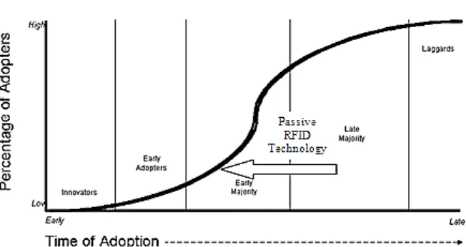
[image:20.595.167.493.526.699.2]RFID is a smart technology that is widely used in the world. For example, RFID is used in supermarket at case and pallet levels such as Wal-Mart, Best-Buy and Target in order to reduce the cost associated with this technology nowadays [2]. RFID is also provides great potential for library system such as broadening access and security. The data of a product can be identified through RFID, it make the mostly industries consider RFID first for tagging their product which can be tracked easily. From the Figure 1.1, the RFID is growing rapidly from the early year. RFID will take over barcode system in one day. Passive RFID technology has greater potential in the future if compared with active RFID due to the price is very cheap. RFID is chosen because it can improve the efficiency in management, production line and industry.
3
Automation is useful and growing rapidly recently. For example, some of the restaurant in Japan are applying automation with conveyor belt sushi. The research had mentioned that automation is able to increase the efficiency of library system. [3] Automation is providing great potential and bring convenience to people around the world. Because of too much books on library, the higher and larger of bookshelf is needed to occupy the number of books. A chair and ladder is needed to pick up or put back the books into the bookshelf. With the smart automation, the injuries case can be reduced or prevented. The injuries case happened which is mentioned in The Brown Daily Herald. [4] Alexandra Ulmer had mentioned that Pereira who is a library technician is needed to a surgery on shoulder and elbow after he had serviced 28 years for the shelving books at Brown with the proven by lawyer. Therefore, this research will determine the possibility of applying automation in library management system.
1.4 Problem Statement
4
1.5 Objective
The main purpose of introducing this project is to design an intelligent smart library system based on RFID Technology with automated system which is returning books to bookshelves and determine the possibility of applying automation system in library for improving the efficiency for library management system. In order to achieve the purpose of the project and to solve the problem occur, the objectives are to design a prototype that able to apply microcontroller technology. The objectives have been listed below must be achieved in completing this project.
a) To design small prototype of smart library system with automated book return system. b) To examine the performance of RFID tag with different placement.
c) To determine the distance of IR line tracking sensor to reflective object in 5 colours- red, orange, yellow, green and blue with the range of input voltage
d) To analyse the transient response of position for servo motor using PID controller.
1.6 Scope
5
1.7 Organization of the Project
6
CHAPTER 2
LITERATURE REVIEW
2.1 Overview
This chapter is about the literature review for the case study which is related to the research. Project background for the research is included in this chapter. The theory on automatic identification and data capture, barcode, RFID, object detection system and system which is to control the DC motor and DC servo motor are included in this chapter.
2.2 Project Background