Surface-controlled properties of myosin studied by
electric field modulation
Harm van Zalingea‡, Laurence C. Ramseya‡, Jenny Aveyarda, Malin Perssonb, Alf Manssonband
Dan V. Nicolaua,c*
aDepartment of Electrical Engineering & Electronics, University of Liverpool, L69 3GJ, United
Kingdom.
bDepartment of Chemistry and Biomedical Sciences, Linnaeus University, 39182 Kalmar,
Sweden.
cDepartment of Bioengineering, McGill University, Montreal, H3A 0C3, Quebec, Canada.
Abstract
(HMM) motor fragments immobilized on various surfaces, is altered by the application of electrical loads generated by an external electric field with strengths ranging from 0 to 8 kVm-1.
Because the motility is intimately linked to the function of surface-immobilized motors, the study also showed how the adsorption properties of HMM on various surfaces, such as nitrocellulose (NC), Trimethylclorosilane (TMCS), Poly(methyl methacrylate) (PMMA), Poly(tert-butyl methacrylate) (PtBMA), and Poly(butyl methacrylate) (PBMA), can be characterized using an external field. It was found that at an electric field of 5 kVm-1 the force
exerted on the filaments is sufficient to overcome the friction-like resistive force of the inactive motors. It was also found that the effect of assisting electric fields on the relative increase of the sliding velocity was markedly higher for the TMCS derivatized surface than for all other, polymer-based surfaces. An explanation for this behavior, based on the molecular rigidity of the TMCS-on-glass surfaces, as opposed to the flexibility of the polymer-based ones, is considered. To this end, the proposed microfluidic device could be used to select appropriate surfaces for future lab-on-a-chip applications as illustrated here for the almost ideal TMCS surface. Furthermore, the proposed methodology can be used to get fundamental insights into the functioning of protein molecular motors, such as the force exerted by the motors in different operational conditions.
1. Introduction
Molecular motors are responsible for the generation of force and for motion at the nanometer scale in biological systems. Linear molecular motors, an essential class among these systems, comprise the sub-classes of myosins,1, 2 kinesins 3, 4 and dyneins.5 An example of force
system through the ATP-fuelled translocation of actin filaments by myosin II motors.6, 7 The
study of molecular motor-induced motion and force-generation in vitro was enabled by the development of the in-vitro motility assay in the late 1980s, which allowed the visualization of the motility of either myosin-coated fluorescent beads moving over surface-bound actin filaments,8, 9 or fluorescently-labelled actin filaments moving over a layer of surface-bound
myosin, or its fragments, e.g., heavy meromyosin (HMM).10 Because the latter architecture of
the motility assay is considerably easier to implement, it has been used extensively for the study of the fundamentals of molecular motor function.11-13
Because the actin-myosin II motor system is critical for the functioning of both skeletal14, 15
and heart muscle,16this system has been comprehensively studied using in vitro motility assays
and other techniques.17, 18 Recently, such studies have aided and continue to aid the development
of acto-myosin active drugs, e.g., in treatment of heart failure and cardiomyopathies.18-20 These
studies would also greatly benefit from experiments where external forces are exerted on the protein motor system, as opposed to the classical studies of unloaded motor proteins, as performed in conventional in vitro motility assays.21, 22
It has been reported previously that due to the negative charge of the actin filaments an electric force can be used to direct their motion in an in-vitro motility assay.23-25 The development of
‘electric motility assays’ would open this classical technique to high-throughput, highly miniaturized studies, which is important for the efficiency of drug discovery efforts,18, 26because
specific myosins can be purified only in small amounts and at high costs, e.g., human myosin with, and without myopathy mutations.27, 28 Furthermore, such ‘electric motility’ lab-on-a-chip
systems would provide important opportunities in molecular motors-driven biocomputation29and
dielectrophoresis,25 as well as of the nano-mechanics of protein molecular motors,31, 32 and their
surface adsorption33, 34 constitute an important basis for such developments. However, the
inter-relationship between these three elements has not been thoroughly considered so far, thus delaying the development of assays where external electric forces are applied in molecular motors-based nanodevices. In addition, there are other design criteria which have not been fully addressed, such as the user-friendliness of the developed devices and the adaptability of the devices for high-throughput applications.
To this end, we propose a simple microfluidics device based on the application of tunable electrophoretic forces on motile actin filaments to demonstrate the control of the motility of cytoskeletal filaments, and probe the impact of surfaces and electric external forces on the function of protein molecular motors, using heavy meromyosin from skeletal muscle as a model system.
2. Experimental Details
2.1. Chemicals and surface functionalization
All chemicals were purchased from Sigma-Aldrich unless otherwise stated, and used as received. The solutions were prepared as follows: Nitrocellulose (NC) 1% (w/v) in amyl acetate; Poly(methyl methacrylate) (PMMA, average Mw=120000) 2% (w/v) in propylene glycol
monomethyl ether acetate (PGMEA); Poly(tertbutyl methacrylate) (PtBMA, average Mw=170000) 2% (w/v) in PGMEA; Poly(butyl methacrylate) (PBMA, average Mw=180000;
nitrogen flow before they were spin coated with the polymer solutions at 3600 rpm for 2 minutes. The cover slips were then baked at 85oC for 3 hours.
For TMCS functionalization, glass cover-slips were soaked in dry acetone, methanol and chloroform for 5 minutes each. The surface treatment is aimed at removing organic contaminants while we rely on the presence of surface silanol groups on glass surfaces under ambient conditions for silanization.5 This is rather similar to the approach used by Sundberg et al.,35
giving TMCS-derivatized surfaces with similar contact angle as in the present work. The cover-slips were then soaked in TMCS for 5 minutes.35 After silanization, cover-slips were rinsed in
dry chloroform, dried under a nitrogen flow and subsequently baked at 85 °C for 1 hour.
The following solutions were used for in vitro motility assays: 1. Low ionic strength solution (LISS), 1 mM MgCl2, 10 mM MOPS, 0.1 mM K2EGTA, pH 7.4. 2. B65, LISS containing 50
mM KCl and 10 mM dithiothreitol (DTT). 3. Assay solution, 1 mM MgATP, 10 mM DTT, 25 mM KCl and LISS with anti-bleach mixture containing 3 mg/ml-1 glucose, 20 units/ml glucose
oxidase, 870 units/ml catalase and ATP regenerating system containing 2.5 mM creatine phosphate and 56 units/ml creatine kinase. 4. Blocking solution; 1 mg ml-1bovine serum albumin
(BSA) in LISS buffer. 5. Labelled actin; 10 µl of rhodamine phallodin labelled actin filaments (rhodamine phalloidin was purchased from Invitrogen and actin was labelled according to manufacturer’s protocol) in 990 µl of B65. 6. Blocking actin solution, 14 µl of unlabeled actin filaments, 986 µl of B65.
2.2. Motility Assay
the cover slip were blocked by applying 60 µl of blocking solution to the flow cell. Following incubation for 30 seconds, the blocking solution in the flow cell was replaced with 60 µl of blocking actin (to block non-functioning HMM heads). After 1 minute incubation, excess blocking actin was removed by flushing the flow cell with 60 µl of B65 and then 60 µl of labelled actin was applied for 30 seconds. At the end of this time period, excess labelled actin was removed by flushing the flow cell with 60 µl of B65 and 60 µl of assay solution was applied.
2.3. Electric Motility Flow Cell
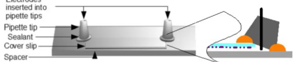
The electric field was applied to the motility assay in a cell as shown in Figure 1. The motility of actin filaments occur on glass cover-slips functionalized as described above. These cover-slips were attached to a microscope slide via thin spacers.10 Tall plastic cones, modified from pipette
tips to hold copper electrodes at the top, were sealed at the open edges of the flow cell.
Figure 1. Device set-up for the electrical motility assay. The spacer creates space between the glass slide and the coverslip. Inset to the right is a cross section of the device at the electrode-end showing its position in the flow cell.
2.4. Visualization of Motility
The movement of the filaments was studied using an epifluorescence microscope (Zeiss Axio Imager.M1) fitted with an Andor iXon+ EMCCD camera at room temperature. Videos were acquired at a frame rate of 10 frames s-1. The analysis of the videos was performed using the
plugin MtrackJ. The velocity of the filaments was characterized by the change in position of the leading end of the filament from frame to frame, while the angle of the movement was determined relative the direction of the positive electrode. Only the filaments that were fully motile for the entire 50 frames of a video were tracked. The average filament length for all experiments was (1.0 ± 0.1) µm (mean ± standard deviation???) . The average velocity as reported in this paper is defined as the velocity from frame to frame for 30 individual filaments.
2.5. Electric Field
During the motility experiments, the electrical field was varied between 0 KVm-1 and 8 KVm -1. The electric field affects the movement of the actin filament because of its negative, linearly
distributed, charge which is recorded as being approximately 4 e-nm-1with e-being the electron
charge, -1.6∙10-19C, with a surface charge density of 0.15 e-nm-2.37, 38
During the experiments the ambient temperature of the flow cell stayed within ±0.2 °C of its mean value and thus it can be concluded that the velocity of actin filaments was not influenced by variations of temperature inside the flow cell.39
3. Results
3.1. Electrically Controlled Motility on Nitrocellulose
Due to the negative charge of the actin filaments (pI = 5.4),40the application of an electric field
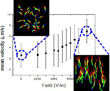
translates into an increase of the apparent velocity of the movement and its guidance towards the positive electrode (Figure 2 inset right). As also observed by others,23, 24 some filaments initially
leading ends, resulted in them quickly making U-turns, followed by movement towards the positive electrode.
Figure 2 presents the absolute value of the sliding velocity of the actin filaments as a function of the strength of the electrical field when the filaments were propelled by HMM immobilized on a nitrocellulose surface. The slope of the velocity vs. field strength plot shows a transition regime starting at 5 kVm-1, above which there is a substantial increase in the slope. Although the force
generated by the electric field rises linearly with the field strength, the response of the actin filaments becomes non-linear due to the various forces that act on the filament, for example the resistive motors will resist motility towards the positive electrode.
electric fields; left: at zero electric field; and right: at 8 kVm-1. The movement starts at the red
end and finishes at the blue end. All experiments were performed at a constant room temperature of 22-23 °C.
Apart from the increase in sliding velocity, the application of an electric field also affected the motion directionality, as can be observed from the two insets in Figure 2. At electric fields close to zero the filaments move randomly, but once the field increases the filaments start to move towards the positive electrode. At the maximum applied field of 8 kVm-1 there are no recorded
movements towards the negative electrode (see also the inset in Figure 3).
3.2. Electrical Motility on Different Surfaces
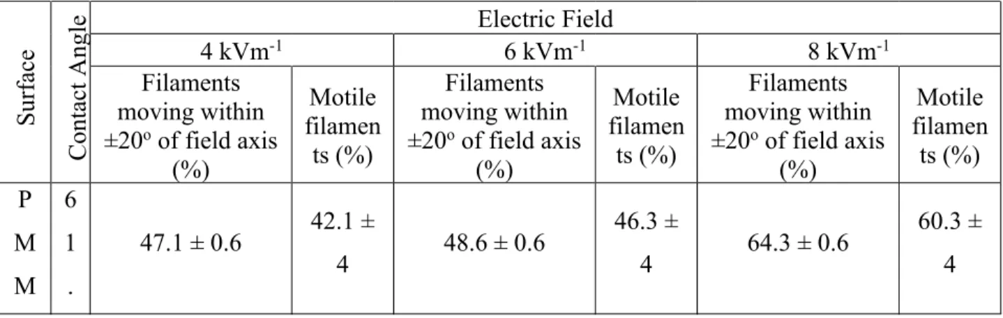
To be able to study how the binding of the myosin to the surface and thus the motility are affected by the surface properties, various surface functionalizations were used. An overview of these and some of their key properties are listed in Table 1.
Table 1. Contact angle and actin filament motility characteristics at different electric field strengths for the various surfaces used to immobilize HMM.
Surfa ce Conta ct Angle Electric Field
4 kVm-1 6 kVm-1 8 kVm-1
Filaments moving within ±20oof field axis
(%) Motile filamen ts (%) Filaments moving within ±20oof field axis
(%) Motile filamen ts (%) Filaments moving within ±20oof field axis
(%) Motile filamen ts (%) P M M 6 1 .
47.1 ± 0.6 42.1 ±
4 48.6 ± 0.6
46.3 ±
4 64.3 ± 0.6
A 5 ± 0 . 6 N C 7 0 . 1 ± 0 . 6
35.5 ± 0.6 30.6 ±
4 47.8 ± 0.6
34.3 ±
4 74.9 ± 0.6
66.9 ± 4 T M C S 7 1 . 0 ± 0 . 6
59.6 ± 0.6 38.7 ±
4 63.9 ± 0.6
44.4 ±
4 66.0 ± 0.6
80.5 ± 4 Pt B M A 8 0 . 1 ± 0 . 6
40.0 ± 0.6 31.9 ±
4 58.7 ± 0.6
33.8 ±
4 60.7 ± 0.6
51.6 ± 4
P B
8
0 41.4 ± 0.6
25.0 ±
4 64.6 ± 0.6
27.1 ±
4 65.3 ± 0.6
M A
. 9 ± 0 . 6
In principle, the electric force applied to actin filaments could result from electrophoresis, dielectrophoresis or electrosmotic flow phenomena. However, the largely symmetric nature of the system involved, i.e., the surface, effectively rules out dielectrophoresis, and the electrically-heterogeneous nature of the protein-functionalized surface, which is deleterious to the formation of contiguous electric double layer, rules out electroosmotic flow. Consequently, the largest contributor to electrical motility is the electrophoretic forces applied to negatively-charged actin filaments.23-25
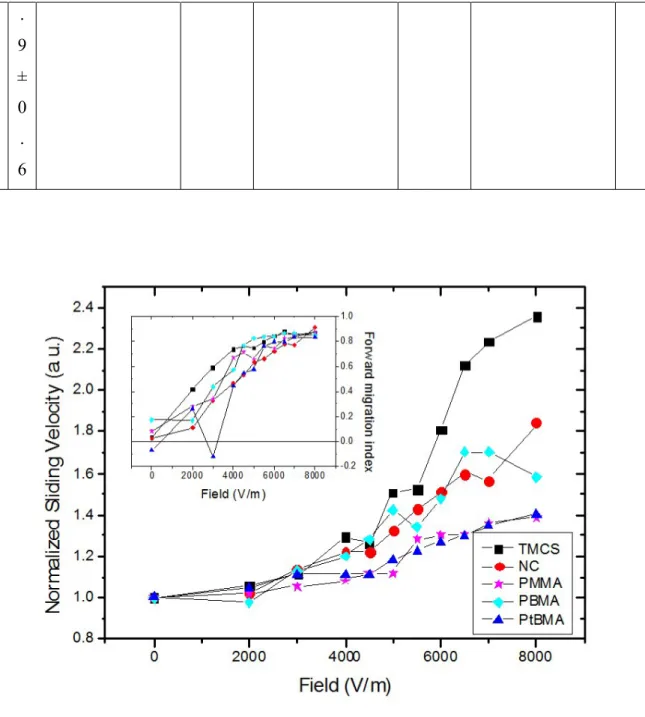
The general relationships between the average velocity of the actin filaments and the strength of the electric fields were similar for different HMM-immobilizing surfaces (Figure 3), i.e., the sliding velocity increased with the increased electric field strengths, with a change in slope at approximately 5 kVm-1. Similarly, the direction of travel of the filaments changed from random
to a parallel motion along the electric field axis as the field strength increased (Table 1). This is highlighted by the inset of Figure 3 in which the forward migration index (FMI) of the experiments is shown. The FMI represents the efficiency of the movement in a particular direction, in this case the actin filament towards the positive electrode. The FMI is defined as
𝑥𝐹𝑀𝐼=1𝑛∑𝑛𝑖=1𝑥𝑑𝑖
𝑖, (1)
where n represents the number of steps, or frames, of the filament movement, x represents the component of the movement of the filament towards the positive electrode, while d represents the total movement of the filament both of which are taken between two subsequent frames. All the effects caused by the electric field were reversible.
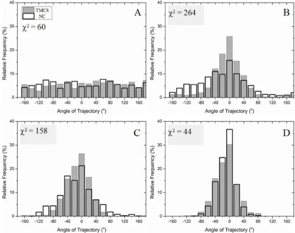
on TMCS, and NC, respectively, which estimates the overlap between the two distributions, shows that the directionality of the filaments on NC and TMCS was very similar, at low, and high strengths of the electric fields.
Figure 4.Distribution of angular sliding directions of actin filaments on model surfaces, i.e., NC and TMCS. 0 degrees represents the axis of the electric field. A) No field applied, B) 4 kV/m, C) 6 kV/m and D) 8 kV/m. The Chi-square values compare the distribution on TMCS with that on NC.
4. Discussion
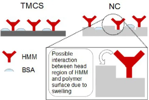
For surfaces with a contact angle in the range 60-80 degrees, as in the present study (Table 1), the HMM molecules adsorb preferentially via their C-terminal tail domain with the N-terminal motor domain extending into solution.21 Despite this favorable molecular positioning, an
essential feature of non-processive motors, such as myosin II, is that a fraction of the motors interacting with the actin filaments are pushing in the direction of the actual movement, while another fraction of the motors oppose this movement, thus effectively creating a resistive force.41, 42 These resistive motors, which do not contribute to motion, comprise both motors that
oppose any motility by holding the filament (e.g., ATP-insensitive rigor-like motors), as well as those that are simply ‘pushing’ in another direction than that of the actual movement, i.e., when they are moved into a drag stroke region by the active motors.42, 43The actual ratio of the active
4.2. The Impact of Surface Molecular Rigidity on Motility
Key properties of the surfaces that impact on the surface-immobilized proteins are surface hydrophobicity, charging and molecular rigidity.44, 45 These properties impact on the
immobilization and function of HMM, as has experimentally been verified for surface hydrophobicity,33, 46 its molecular rigidity 47and its charge.33 While these parameters are
interlinked to some extent and additional effects might play a role in the determination of the motility function, a selection of surfaces that have similar parameters bar one would allow the assessment of that single parameter. Because NC and TMCS surfaces have very similar hydrophobicity (Table 1) and both are negatively charged, the remaining and important difference is their molecular rigidity.33, 48Indeed, the TMCS-functionalized glass will not absorb
Figure 5.Different architectures of HMM-immobilizing surface on rigid (e.g., TMCS) surfaces; and top-swelled polymeric (e.g., NC) surfaces.
However, the similarity in the motility behavior on NC and TMCS in the absence of an electric field (Figure 3) suggests that any difference in the binding characteristics of the two surfaces is rather small, when external forces are not exerted on the actin filaments. Indeed, this is in agreement with previous findings showing that the adsorption of HMM and blocking protein prior to the actual motility assay result in a protein layer which decreases the difference between the overall rigidity of the NC and TMCS surfaces.47The coating of surfaces with NC10, 12, 49 and the functionalization with TMCS33, 43 have been used extensively as immobilizing
surfaces for HMM in studies of motor protein function. Both these surface substrates are relativity hydrophobic and it has been shown in numerous motility studies that both TMCS and NC exhibit fully functioning myosin motors.22, 46, 50-53
motility behavior differed between the two surfaces. In particular, the motility appeared to be less hindered on TMCS than on NC, as inferred by the larger increase in the velocity on these surfaces when the electric fields strength increases from 0 to 8 kVm-1. In the framework of the
proposed model of the interaction between HMM and the immobilizing surface, it appears that the more exposed protein architecture on TMCS-functionalized surfaces allows a more direct, and thus a more effective interaction with the electric fields, than on the more embedded architecture on NC surfaces. This finding is consistent with better (higher velocity and fraction of motile filaments) and more reproducible motility previously observed on TMCS-derivatized compared to NC surfaces.35, 54
4.3. The Impact of Surface Hydrophobicity on Motility
In order to examine the effect of hydrophobicity, the motility on a range of polymer coatings (PtBMA, PBMA and PMMA) was compared to the motility on NC. In contrast to NC and TMCS, the polymers PtBMA and PBMA are not commonly used as a substrates for protein immobilization, but they have, as well as PMMA,46, 54, 55 been shown to support actin myosin
motility.22Among these polymers, PMMA is relatively hydrophilic (see Table 1). It differs from
PtBMA and PBMA in the end ester group linked to the methacrylic backbone polymeric chain. Therefore any changes in the HMM immobilization-induced properties of the surface are due to the chemical characteristics and not the structural properties.
One property which distinguishes the motility function of the various surfaces is the steep increase in the average sliding velocity of actin filaments in the mid-range (4.5 - 6 kVm-1) upon
further increase in electric field strength (Figure 3).24 Interestingly, the behavior is consistent
elastic elements. 56, 57 When looking at the information obtained from the directionality of the
filament movement as shown in Figure 4 and Table 1, the main observation is that the degree of directionality increases in parallel with the increase in velocity. When the electric field was switched on, the negatively charged filaments responded to the force generated by the field and moved towards the positive electrode (0°). In general, at 5 kVm-1, all filaments on all the various
substrates moved within ±90° from the positive electrode, changing to ±40° at the maximum field of 8 kVm-1.
The fact that the increase in sliding velocity as a function of electric field, the directionality as well as the percentage of motile filaments all occur at 5 kVm-1 gives a possible insight into its
cause. While the motility function is determined by the ability of the apex of the filament to find the next molecular motor, this is complicated by the fact that the motors have a preferential direction in which they propel the filaments and the presence of ‘dead’ motors which resist motion completely. If the force generated by the electric field at the threshold value of 5 kVm-1is
similar to the force generated by the resistive motors, at higher field strengths more filaments, which were blocked by these motors, will start to move, and thus an increase in the percentage of motile filaments will be observed. While at low fields the direction of the apex of the actin filament is governed by Brownian motion, as the strength of the field is increased, the movement of the apex is forced towards the positive electrode, resulting in the apex finding less motors in its path. Additionally, the longer time span between the attachment of the apex to subsequent motors allows the field to transfer more force onto the filament and hence an increased acceleration can be observed.
has been compared to.21, 33, 35This behavior has been explained by the predominant adsorption of
HMM motor fragments via their most C-terminal tail domain to a TMCS functionalized surface. Such an adsorption mechanism, with the myosin heads more than 30 nm from the surface21 has
been attributed to the moderate hydrophobicity of TMCS and a low negative electric charge density, partly repelling the HMM C-terminal.21, 33, 35 This mode of adsorption would make the
subfragment 2 (S2), tail fragment of actin-attached HMM amenable to buckling when subjected to assistive forces acting in the same direction as the motor driven filament sliding.58, 59 Such
properties seem to be consistent with substantial increase in velocity with increased assisting loads (e.g., due to electric fields) because the S2-fragments of actin-attached HMM give minimal internal resistance to sliding. The difference between TMCS and the other substrates in the velocity versus field-strength plots may be due to the lack of S2 buckling on the latter substrates. This could be the result if the negatively charged subfragment 2, or one of the myosin heads (Figure 5), is bound to the underlying surface in the polymer substrates either due to increased surface roughness, or specific chemical properties.
4.4. On the design of a future high-throughput electric motility assay
The overall design of the motility chamber in the present study is built on the standard design of flow cells in conventional motility assays.10 In spite of the simplicity of the design, the
establishment of essentially parallel electric field lines, thus creating an area where all filaments and motors experience a similar electrophoretic force, both in amplitude and direction.
In future electric motility lab-on-a-chip devices, whether for drug discovery, diagnostics or biocomputation, it will be important to select an appropriate surface substrate for adsorption of motor fragments. Particularly important for the fundamental studies and those focused on drug-discovery, it is important to consider the fact that the myosin motor fragments have different properties on different substrates, as shown above. We have shown that motility is of good quality on both NC and TMCS, as well as on PMMA. Out of these substrates, TMCS and NC have advantages by virtue of the long technological experience and careful characterization of HMM function, whereas PMMA is a material widely used in the fabrication of microfluidic devices. A disadvantage of NC, not present for PMMA and TMCS, is that it is not readily micro-, or nano-patterned, which may be important in certain applications requiring the confinement of the movement of actin filaments.
5. Conclusion
of the sliding velocity was markedly higher for TMCS than any other surfaces tested with implications for the design of future high-throughput electric motility assays. The directionality of the motility was observed to be different at intermediate field strengths, but similar at the high and low fields when comparing rigid and non-rigid surfaces.
AUTHOR INFORMATION
Corresponding Author
* Corresponding Author e-mail: [email protected]
Author Contributions
The manuscript was written through contributions of all authors. All authors have given approval to the final version of the manuscript. ‡These authors contributed equally.
Funding Sources
The authors would like to acknowledge funding from the European Union Seventh Framework Programme ([FP7/2007-2011]) under grant agreement number 228971 (MONAD) and from the Swedish Research Council (grant # 621-2010-5146).
REFERENCES
1. Sellers, J. R.; Veigel, C., Walking with myosin V. Curr. Opin. Cell Biol.2006, 18, (1), 68-73.
2. Sweeney, H. L.; Houdusse, A., Structural and functional insights into the myosin motor mechanism.Annu. Rev. Biophys.2010,39, 539-557.
3. Block, S. M., Kinesin motor mechanics: Binding, stepping, tracking, gating, and limping. Biophys. J.2007,92, (9), 2986-2995.
4. Hirokawa, N.; Noda, Y.; Tanaka, Y.; Niwa, S., Kinesin superfamily motor proteins and intracellular transport.Nat. Rev. Mol. Cell Biol.2009,10, (10), 682-696.
6. Huxley, A. F.; Niedergerke, R., Structural change in muscle during contraction -interference microscopy of living muscle fibres.Nature1954,173, (4412), 971-973.
7. Huxley, H.; Hanson, J., Changes in the cross-striations of muscle during contraction and strech and their structural interpretation.Nature1954,173, (4412), 973-976.
8. Sheetz, M. P.; Spudich, J. A., Movement of Myosin-Coated Fluorescent Beads on Actin Cables Invitro.Nature1983,303, (5912), 31-35.
9. Spudich, J. A.; Kron, S. J.; Sheetz, M. P., Movement of myosin-coated beads on oriented filaments reconstituted from purified actin.Nature1985,315, (6020), 584-586.
10. Kron, S. J.; Spudich, J. A., Fluorescent actin filaments move on myosin fixed to a glass surface.P. Natl. Acad. Sci. USA1986,83, (17), 6272-6276.
11. Harada, Y.; Noguchi, A.; Kishino, A.; Yanagida, T., Sliding movement of single actin filaments on one-headed myosin filaments.Nature1987,326, (6115), 805-808.
12. Toyoshima, Y. Y.; Kron, S. J.; Spudich, J. A., The myosin step size: measurement of the unit displacement per ATP hydrolyzed in an in vitro assay. P. Natl. Acad. Sci. USA 1990,87, 7130-7134.
13. Uyeda, T. Q. P.; Abramson, P. D.; Spudich, J. A., The neck region of the myosin motor domain acts as a lever arm to generate movement. P. Natl. Acad. Sci. USA 1996,93, (9), 4459-4464.
14. Spudich, J. A.; Huxley, H. E.; Finch, J. T., Regulation of skeletal muscle contraction. II. Structural studies of the interaction of the tropomyosin-troponin complex with actin. J. Mol. Biol.1972,72, (3), 619-"620,IN5-IN16,IN18-IN19,621-632".
15. Spudich, J. A.; Watt, S., The regulation of rabbit skeletal muscle contraction. I. Biochemical studies of the interaction of the tropomyosin-troponin complex with actin and the proteolytic fragments of myosin.Journal of Biological Chemistry1971,246, (15), 4866-4871. 16. Alpert, N. R.; Hamrell, B. B.; Mulieri, L. A., Heart muscle mechanics. Annual Review of Physiology1979,41, 521-537.
17. Behrmann, E.; Müller, M.; Penczek, P. A.; Mannherz, H. G.; Manstein, D. J.; Raunser, S., Structure of the rigor actin-tropomyosin-myosin complex.Cell2012,150, (2), 327-338. 18. Spudich, J. A., Hypertrophic and dilated cardiomyopathy: Four decades of basic research on muscle lead to potential therapeutic approaches to these devastating genetic diseases. Biophysical Journal2014,106, (6), 1236-1249.
19. Cleland, J. G. F.; Teerlink, J. R.; Senior, R.; Nifontov, E. M.; McMurray, J. J. V.; Lang, C. C.; Tsyrlin, V. A.; Greenberg, B. H.; Mayet, J.; Francis, D. P.; Shaburishvili, T.; Monaghan, M.; Saltzberg, M.; Neyses, L.; Wasserman, S. M.; Lee, J. H.; Saikali, K. G.; Clarke, C. P.; Goldman, J. H.; Wolff, A. A.; Malik, F. I., The effects of the cardiac myosin activator, omecamtiv mecarbil, on cardiac function in systolic heart failure: A double-blind, placebo-controlled, crossover, dose-ranging phase 2 trial.The Lancet2011,378, (9792), 676-683.
20. Fedorov, R.; Böhl, M.; Tsiavaliaris, G.; Hartmann, F. K.; Taft, M. H.; Baruch, P.; Brenner, B.; Martin, R.; Knölker, H. J.; Gutzeit, H. O.; Manstein, D. J., The mechanism of pentabromopseudilin inhibition of myosin motor activity. Nat. Struct. Mol. Biol. 2009, 16, (1), 80-88.
22. Hanson, K. L.; Solana, G.; Nicolau, D. V., Effect of surface chemistry on in vitro actomyosin motility. InBiomedical Applications of Micro- and Nanoengineering II, Nicolau, D. V., Ed. Spie-Int Soc Optical Engineering: Bellingham, 2005; Vol. 5651, pp 13-18.
23. Hanson, K. L.; Solana, G.; Nicolau, D. V., Electrophoretic control of actomyosin motility.Proc. of SPIE2005,5699, 196-201.
24. Riveline, D.; Ott, A.; Julicher, F.; Winkelmann, D. A.; Cardoso, O.; Lacapere, J. J.; Magnusdottir, S.; Viovy, J. L.; Gorre-Talini, L.; Prost, J., Acting on actin: the electric motility assay.Eur. Biophys. J. Biophys.1998,27, (4), 403-408.
25. van den Heuvel, M. G. L.; Butcher, C. T.; Lemay, S. G.; Diez, S.; Dekker, C., Electrical docking of microtubules for kinesin-driven motility in nanostructures. Nano Lett. 2005, 5, (2), 235-241.
26. McMurray, J. J. V., Heart failure in 2011: Heart failure therapyĝ€"technology to the fore. Nature Reviews Cardiology2012,9, (2), 73-74.
27. Resnicow, D. I.; Deacon, J. C.; Warrick, H. M.; Spudich, J. A.; Leinwand, L. A., Functional diversity among a family of human skeletal muscle myosin motors. Proceedings of the National Academy of Sciences of the United States of America2010,107, (3), 1053-1058. 28. Sommese, R. F.; Sung, J.; Nag, S.; Sutton, S.; Deacon, J. C.; Choe, E.; Leinwand, L. A.; Ruppel, K.; Spudich, J. A., Molecular consequences of the R453C hypertrophic cardiomyopathy mutation on human β-cardiac myosin motor function. Proceedings of the National Academy of Sciences of the United States of America2013,110, (31), 12607-12612.
29. Nicolau, D. V.; Nicolau Jr, D. V.; Solana, G.; Hanson, K. L.; Filipponi, L.; Wang, L.; Lee, A. P., Molecular motors-based micro- and nano-biocomputation devices. Microelectronic Engineering2006,83, (4-9 SPEC. ISS.), 1582-1588.
30. Korten, S.; Albet-Torres, N.; Paderi, F.; Ten Siethoff, L.; Diez, S.; Korten, T.; Te Kronnie, G.; Månsson, A., Sample solution constraints on motor-driven diagnostic nanodevices. Lab on a Chip - Miniaturisation for Chemistry and Biology2013,13, (5), 866-876.
31. Fulga, F.; Nicolau, D. V., Models of protein linear molecular motors for dynamic nanodevices.Integr Biol2009,1, (2), 150-169.
32. Howard, J.,Mechanics of Motor Proteins and the Cytoskeleton. Sinauer Associates, Inc.: Sunderland, Massachusetts, 2001.
33. Albet-Torres, N.; O'Mahony, J.; Charlton, C.; Balaz, M.; Lisboa, P.; Aastrup, T.; Månsson, A.; Nicholls, I. A., Mode of heavy meromyosin adsorption and motor function correlated with surface hydrophobicity and charge.Langmuir2007,23, (22), 11147-11156. 34. Fischer, T.; Hess, H., Materials chemistry challenges in the design of hybrid bionanodevices: Supporting protein function within artificial environments.Journal of Materials Chemistry2007,17, (10), 943-951.
35. Sundberg, M.; Rosengren, J. P.; Bunk, R.; Lindahl, J.; Nicholls, I. A.; Tagerud, S.; Omling, P.; Montelius, L.; Mansson, A., Silanized surfaces for in vitro studies of actomyosin function and nanotechnology applications.Anal. Biochem.2003,323, (1), 127-138.
36. Schneider, C. A.; Rasband, W. S.; Eliceiri, K. W., NIH Image to ImageJ: 25 years of image analysis.Nature Methods2012,9, (7), 671-675.
37. Hase, M.; Yoshikawa, K., Structural transition of actin filament in a cell-sized water droplet with a phospholipid membrane.J. Chem. Phys.2006,124, (10).
39. Rossi, R.; Maffei, M.; Bottinelli, R.; Canepari, M., Temperature dependence of speed of actin filaments propelled by slow and fast skeletal myosin isoforms. J. Appl. Physiol.2005,99, (6), 2239-2245.
40. Zechel, K.; Weber, K., Actins from mammals, bird, fish and slime mold characterized by isoelectric focusing in polyacrylamide gels. European Journal of Biochemistry 1978, 89, (1), 105-112.
41. Huxley, A. F., Muscle Structure and Theories of Contraction. Prog. Biophys. Mol. Bio.
1957,7, 255.
42. Pate, E.; White, H.; Cooke, R., Determination of the myosin step size from mechanical and kinetic data.P. Natl. Acad. Sci. USA1993,90, (6), 2451-2455.
43. Persson, M.; Bengtsson, E.; Ten Siethoff, L.; Månsson, A., Nonlinear cross-bridge elasticity and post-power-stroke events in fast skeletal muscle actomyosin. Biophysical Journal
2013,105, (8), 1871-1881.
44. Kim, D.; Herr, A. E., Protein immobilization techniques for microfluidic assays. Biomicrofluidics2013,7, (4).
45. Vasina, E. N.; Paszek, E.; Nicolau Jr, D. V.; Nicolau, D. V., The BAD project: Data mining, database and prediction of protein adsorption on surfaces. Lab on a Chip -Miniaturisation for Chemistry and Biology2009,9, (7), 891-900.
46. Nicolau, D. V.; Solana, G.; Kekic, M.; Fulga, F.; Mahanivong, C.; Wright, J.; dos Remedios, C. G., Surface Hydrophobicity Modulates the Operation of Actomyosin-Based Dynamic Nanodevices.Langmuir2007,23, (21), 10846-10854.
47. Van Zalinge, H.; Aveyard, J.; Hajne, J.; Persson, M.; Mansson, A.; Nicolau, D. V., Actin filament motility induced variation of resonance frequency and rigidity of polymer surfaces studied by quartz crystal microbalance.Langmuir2012,28, (42), 15033-15037.
48. Low, S. C.; Shaimi, R.; Thandaithabany, Y.; Lim, J. K.; Ahmad, A. L.; Ismail, A., Electrophoretic interactions between nitrocellulose membranes and proteins: Biointerface analysis and protein adhesion properties.Colloids and Surfaces B: Biointerfaces2013,110, 248-253.
49. Homsher, E.; Wang, F.; Sellers, J. R., Factors affecting movement of F-actin filaments propelled by skeletal muscle heavy meromyosin. American Journal of Physiology - Cell Physiology1992,262, (3 31-3), C714-C723.
50. Balaz, M.; Sundberg, M.; Persson, M.; Kvassman, J.; Monsson, A., Effects of surface adsorption on catalytic activity of heavy meromyosin studied using a fluorescent ATP analogue. Biochemistry2007,46, (24), 7233-7251.
51. Spudich, J. A., How Molecular Motors Work.Nature1994,372, (6506), 515-518.
52. Sellers, J. R., In Vitro Motility Assay to Study Translocation of Actin by Myosin. In Current Protocols in Cell Biology, John Wiley & Sons, Inc.: 2001.
53. Warshaw, D. M., The in vitro motility assay: A window into the myosin molecular motor.News in Physiological Sciences1996,11, 1-7.
54. Sundberg, M.; Balaz, M.; Bunk, R.; Rosengren-Holmberg, J. P.; Montelius, L.; Nicholls, I. A.; Omling, P.; Tagerud, S.; Mansson, A., Selective spatial localization of actomyosin motor function by chemical surface patterning.Langmuir2006,22, (17), 7302-7312.
56. Edman, K. A. P., The velocity of unloaded shortening and its relation to sarcomere length and isometric force in vertebrate muscle fibres.J. Physiol.1979,VOL 291, 143-159.
57. Edman, K. A. P., The force-velocity relationship at negative loads (assisted shortening) studied in isolated, intact muscle fibres of the frog.Acta Physiologica2014,211, (4), 609-616. 58. Albet-Torres, N.; Gunnarsson, A.; Persson, M.; Balaz, M.; Hook, F.; Mansson, A., Molecular motors on lipid bilayers and silicon dioxide: different driving forces for adsorption. Soft Matter2010,6, (14), 3211-3219.