i MICROSTRIP ARRAY ANTENNA DESIGN WITH EBG STRUCTURE AT 28GHz
ADIBA SOLIHA BT SAADON
This Report Is Submitted In Partial Fulfilment of Requirement For The Bachelor Of Degree Electronic Engineering (Telecommunication )
Fakulti Kejuteraan Elektronik Dan Kejuteraan Komputer Universiti Teknikal Malaysia Melaka.
ii I hereby declare this report entitle “ Microstrip Array Design with EBG Structure at 28GHz “
is my the result of my own research except cited in the reference
iii To my beloved parents,
Saadon Mat Saad and Wan Khairani Wan Muhammad.
To my talented supervisor , Dr Imran bin Mohd Ibrahim
iv
ACKNOWLEDGEMENT
I would like to thank Allah S.W.T who give me strength to complete my Final Year Project. Alhamdulilah with deepest gratitude and appreciation. To my beloved parents, Saadon bin Mad Saat and Wan Khairani binti Wan Muhammad who always support me , financially and morally , who always supply my needs and understand me.
I would like to thank my supervisor , Dr Imran bin Mohd Ibrahim who always shared knowledge and continuously help me with variety of knowledge from nothing to something. I would like to thank my best friend, Muhammad Adli bin Abdul Rahman, who lend me his laptop upon my thesis completion.
v
ABSTRACT
vi ABSTRAK
vii
TABLE OF CONTENT
CHAPTER CONTENT PAGE
PROJECT TITLE I
APPROVAL II
DEDICATION III
ACKNOWLEDGEMENT IV
ABSTRACT ( ENGLISH ) V
ABSTRACT ( BAHASA MALAYSIA) VII
TABLE OF CONTENT VIII
LIST OF TABLES VI
LIST OF FIGURES
1 INTRODUCTION AND BACKGROUND RESEARCH
1.1 INTRODUCTION 1
1.2 PROBLEM STATEMENT 4
1.3 OBJECTIVES 4
1.4 SCOPE OF WORK 4
1.5 ORGANIZATION OD THESIS 5
2 LITERATURE REVIEW
2.1 INTRODUCTION 6
viii
2.3 MICROSTRIP ANTENNA 9
2.4 MICROSTRIP ARRAY ANTENNA 11
2.5 ELECTROMAGNETIC BAND GAP (EBG) 15
2.6 SUMMARY 22
3 METHADOLOGY
3.1 INTRODUCTION 23
3.2 FLOW CHART OF METHODOLOGY 24
3.3 DESIGN PROCEDURE 24
3.4 MICROSTRIP ARRAY ANTENNA 28
3.5 DESIGN OF EBG STRUCTURE 27
3.6 DESIGN OF INTEGRATION OF MICROSTRIP
ARRAY ANTENNA AND EBG 27
3.7 SUMMARY
4 RESULT AND DISCUSSION
4.0 INTRODUCTION
4.1 DESIGN SPECIFICATION OF MICROSTRIP
4.2 SINGLE PATCH MICROSTRIP
4.3 1x2 ARRAY MICROSTRIP PATCH
4.4 4x1 MICTROSTRIP PATCH ARRAY
4.5 4x2 MICROSTRIP PATCH ARRAY 41
ix
4.7 ELECTROMAGNETIC BAND GAP STRUCTURE 44
4.8 INTEGRATION OF MICROSTRIP ARRAY
ANTENNA WITH EBG 49
4.9 SUMMART OF RESULT 58
4.10 ARRANGEMENT AND DESIGN OF EBG 60
4.11 SUMMARY 63
5 CONCLUSION 64
5.1 CONCLUSION 64
5.2 FUTURE WORK 65
x
LIST OF TABLES
TABLE NO TITLE PAGE
1 Result obtained of Microstrip Patch
Antennas 13
2 A comparison details between the
results of the polar plot diagrams 15
3 Comparison of EBG Structure and its
transmission coefficient 16
4 Result obtained from comparison of
EBG Structure 16
5 Performance parameter of microstrip
array antennna 17
6 The comparison with and without
xi
LIST OF FIGURES
FIGURE NO. TITLE PAGE
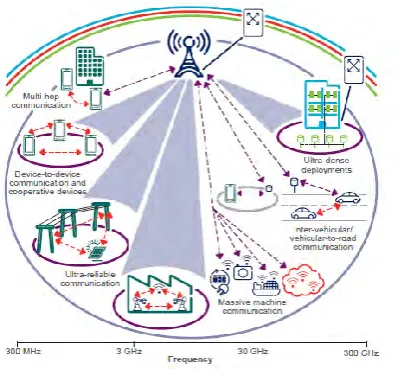
1.1 Antenna application 1
1.2 High Gain Antenna 3
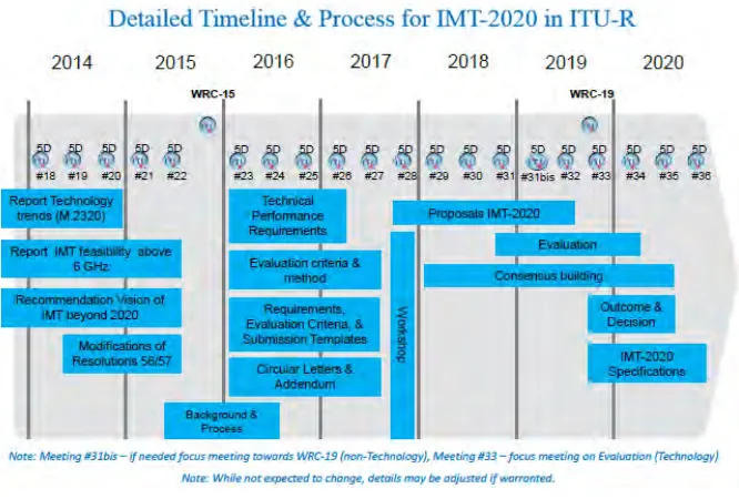
2.1 Timeline of 5G Development 7
2.2 Standard frequency of 5G 7
2.3 Radiation Pattern in polar and cartersian showing
various lobe 9
2.4 Beamwidth 10
2.5 Return Loss 11
2.6 Microstrip Patch 12
2.7 Microstrip feed 13
2.8 Gap coupled microstrip feed 13
2.9 Inset feedline 13
xii
2.11 Comparison of surface wave current 16
2.12 Comparison of 3D result with and without EBG 19
3.1 Flowchart 24
3.2 Microstrip patch with inset feed 28
3.3 Impedance Matching 29
3.4 Development of Microstrip Patch Antenna 30
3.5 Mushroom EBG 31
3.6 Fractal EBG 31
3.7 Microstrip Integrated with EBG 32
3.8 Capacitor and Inductor of EBG 33
4.1 Front view , perspective view and back view of single
patch 35
4.2 Single patch S parameter 36
4.3 Gain value of single patch 36
4.4 Structure of 1x2 microstrip patch array 37
4.5 S Parameter of 2x1 microstrip array 38
4.6 Gain result of 1x2 microstrip array 38
4.7 Radiation pattern of 1x2 microstrip array antenna 39
xiii
4.9 a) S parameter of 4x1 microstrip array antenna 40
4.10 Gain result of 4x1 microstrip patch antenna 41
4.11 Structure of 4x2 microstrip array patch antenna 41
4.12 S parameter of 4x2 microstrip array antenna 42
4.13 Gain result of 4x1 microstrip patch antenna 42
4.14 Radiation pattern of 4x2 microstrip array antenna 43
4.15 Basic design of electromagnetic band gap 44
4.16 Structure mushroom EBG front and LC circuit that
represent EBG 45
4.17 S parameter of mushroom EBG 46
4.18 Front and perspective view of fractal EBG 1st design 46
4.19 Structure of fractal EBG 2nd design front view and
perspective view 47
4.20 S parameter of fractal EBG structure comparison 48
4.21 Structure of single microstrip antenna with EBG 48
4.22 The comparison of S parameter microstrip single patch
antenna with and without EBG 49
4.23 Directivity result of single patch antenna with EBG 50
4.24 Gain result of single patch antenna with EBG 50
4.25 Structure of microstrip array antenna 2x1 with 51
4.26 The comparison of S parameter microstrip single patch
xiv
4.27 Gain result of microstrip 1x2 patch antenna 52
4.28 Structure of 4x1 microstrip array antenna 52
4.29 The comparison of S parameter between with and
without EBG 53
4.30 Comparison of radiation pattern at H plane 53
4.31 Comparison of radiation pattern at E plane 54
4.32 The gain result of microstrip 4x1 antenna structure
with EBG 54
4.33 Structure of microstrip array 4x2 with EBG Structure 55
4.34 The comparison of S Parameter between with and
without EBG 55
4.35 Comparison of radiation pattern at H plane 56
4.36 Comparison of radiation pattern at E plane 56
4.37 Comparison of radiation pattern E plane and H plane 56
4.38 Directivity of the microstrip array antenna 4x2 with
EBG 57
4.39 Gain of the microstrip array antenna 4x2 with EBG 58
4.40 Comparison of all the return loss value 59
4.42 Comparison of radiation pattern 59
4.43 Radiation pattern of modified EBG 61
4.44 Gain result of modified EBG 61
xv
4.46 Back view of modified structure 62
1
CHAPTER 1
INTRODUCTION
1.1Introduction
Antenna is one of the important elements in our daily life .Antenna is one of the RF system for receiving or transmitting the radio wave signals from and into air as a medium. The signal will be not generated by the system as it will not received and transmit without the proper design of the design. Many types of antenna with various frequency has ben design to meet the applications that suitable for human needs.
[image:16.595.221.420.561.745.2]
2
The illustrations shows that the antenna with different frequency is used for many application such as a device to device communication and cooperative devices which can connect peoples. Other than that antenna is used for ultra-dense deployment, massive machine communication in industry and inter-vehicular to road communication. Antenna also had wide application in biomedical application.All this application consists of many types of frequency which controlled by the highest frequency of antenna. This is because the process of receiving and transmitting controlled by the high gain antenna.
1.1.1 History of 5G
5G is the name currently given to the next generation of the mobile data connectivity that will come after the generation of 4G. It will provide unbelievable fast broadband speed and more importantly it have the capacity to perform every function you want without drop in speed or connection no matter how many people connect it on the same time. Antenna has revolve from years to years from 1G to 5G. Description below will explain what is tbe properties of 1G until 5G.
1G was used for basic phone calls but was a very weak, insecure signal.
2G was a step up from 1G, adding digital phone calls and messaging, but too slow
to manage Internet access in most cases.
3G offered messaging and data on top of 2G, bringing about a better mobile Internet
experience. 3.5G enhances this further, bringing the standard to the level of low-end broadband Internet.
4G offered full IP services, with an even faster broadband connection with lower
3
5G’s goal is to be the ultimate wireless experience with wireless speed from10Mbps
to 100Mbps and higher.
One of the main benefits of 5G over 4G s the latency. At present 4G is capable of between 40ms to 60ms , which is low in latency but not enough to provide real time response. For the example, in a multilayer gaming , requires a low latency to ensure that the remote server response instantly when we hit the button.
5G prospective ultra low latency could occur in the range of 1ms to 10ms. With this technology , a spectator in a football stadium can watch a live stream of an alternative camera angle of action that matches what is going on the pitch ahead with no perceivable delay. Another important factor of is the capacity of the data, with the Internet of Things being used more and more over time, where gadgets and objects employ smart , connected features that they have never had before , the strain on bandwidth will continue to grow. 5G also benefits to the society and it is one of the energy adapted solution.
1.1.2 High Gain Antenna
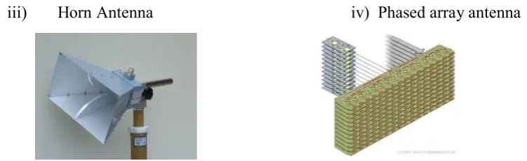
High gain antenna or known as directional antenna is an antenna with a narrow radio beam that is used to increased signal strength. High gain antenna provide a precise way to target radio signals . This antenna is used in space missions as well as in flat, open areas where geography won’t disturbs the radio waves.A low gain antenna is an omnidirectional antenna with a broad radiowave beam width that allows for the signal to propagate well even in mountainous regions and thus more reliable regardless of terrain.High gain antenna transmits more power to the receiver , increasing the strength of the signal it receives. As a results of their directivity, directional antennas send fewer signals from a direction other than the main beam. This property reduced interference. There are many types of high directional antenna such as
4
iii) Horn Antenna iv) Phased array antenna
1.2Problem Statement
One of problem faced nowadays is there were congested data usage because there are millions of things connected to the internet. The gain of current antenna is cannot support the device connecting to the antenna and the demand by emerging technology needs a high gain antenna. Next , in the microstrip antenna design , the main problem faced is the propagation of the surface wave in the substrate which occurs because of the increment of side lobe and backlobe . In the array design , another problem occur which is mutual coupling occur when more than one element placed near each other and existence of side lobe. In this thesis, an EBG structure as introduced to reduced the effect of surface wave and mutual coupling.
1.3. Objectives
[image:19.595.148.524.99.214.2]The main objectives is to design antenna at 28GHz which is Microstrip Antenna Array with EBG Structure on CST software . Next the objective is to analyse the output of the microstrip array antenna with EBG structure. Finally, by introducing the EBG structure, the target is to reduce the antenna side lobe of microstrip array , thus increase the gain performance up to 16.5dB according to standard ITU-R WP5D.
5
1.3Scope of Work
The project focuses on the development of the antenna to meet the satisfied performance of high gain antenna at 28 GHz. The first part of the project is to study the concept of the antenna properties, microstrip patch antenna , microstrip array antenna , microstrip antenna with various type of feeding techniques and electromagnetic band gap (EBG) structure.
In the second part of the project of the performance of the EBG structure, microstrip array antenna with and without EBG will be investigated by performing simulation in CST software. This antenna will be designed to operate at frequency of 28 GHz. The antenna is at very high frequency , thus an array 2x1 , 2x2 , 4x2 , 16x2 design was done to meet the specification. However there is still side lobe found on the radiation gain.
In the third part of the project, an EBG structure is implemented in the microstrip array antenna. The EBG type of structure was investigate and the best location of EBG structure on the microstrip array was then discovered.
Lastly , the result obtained from the simulation is tabulated and discussed.The antenna was not fabricated because of the limitation of the equiptment in Malaysia which cannot
1.4Organization of Thesis
This thesis consists of five chapter that describing the work done in the project. The thesis organization is generally described as follows.
The first chapter explains the introduction of the project , the problem statement and objectives of the project. Other than that , this chapter explain about the scope of work and the chapter’s flow.
6
chapter explain the basic parameter of the antenna and theoretical about EBG structure.
Chapter three which is methodology discussed about the steps in designing the microstrip array antenna, EBG structure and the combining of EBG Structure to the microstrip antenna. The design start by the calculation and followed by the simulation
7
CHAPTER 2
LITERATURE REVIEW
2.0 Introduction
As the activity of 4G cellular accelerates, there is an increasing interest in that will define the next generation 5G telecommunication. A key feature of 4G, is ability to support high data rate, thus the focus of emerging technology is coverage and user experience. To ensure that, the best design of antenna must be produced by enhancing the properties of the antenna and overcome the problem faced by the antenna.
2.1 Standardization of 5G
8
International Mobile Telecommunication) are working on realizing the future vision of mobile broadband 5G. [31]
In early 2012, ITU-R embark on a programme to develop “ IMT for 2020 and beyond” and through the leading role of Working Party 5D , ITU’s radiocommunication sector (ITU-R) has finalized its view a timeline towards 2020
[image:23.595.176.509.201.426.2]Figure above show the timeline plan of 5G development by ITU-R WP5D. Thus , the 5G draft report shows that the 5G frequency is from 6 GHz to 60 GHz. However the 60 GHz is unlicensed , 38 GHz with 3.4GHz band, and 28 GHz is LMDS .
Figure2.1: The timeline plan of 5G Development
9
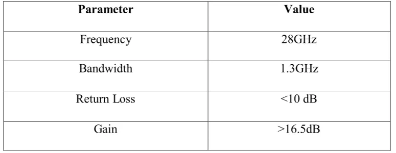
In figure 2.2 above shows that the area of each square shows the relative bandwidth . Current cellular spectrum in band 700 MHz to 2.6 GHz provide at most 150 MHz to 200 MHz. Thus , according to the standard figure above , it explain that in 5G at 28 GHz, the bandwidth must be 1.3 Ghz , the return loss must be below -10 dB and the gain of the antenna mus be at least -16.5 dB. Thus in this project , the standardize will be followed.
2.2 Antenna Properties
Antenna is a device that convert a guided electromagnetic wave on transmission line into a plane wave propagating in free space. Thus, one side of antenna appears as electrical circuit element , while the other side as an interface with propagating plane wave. Antenna can be used for both transmit and receive function [1]. A variety of antennas have been developed for different function
1. Wire antennas - used at low frequency such as dipole, monopole and horns 2. Aperture Antennas - mostly common used at mocrowaves and milimeter wave
frequency ( rectangular and waveguide)
3. Printed antennas – Can easily arrayed for high ( microstrip patch antenna) 4. Array antennas - consists of regular arrangement with feed network ( phased
array)
Parameter Value
Frequency 28GHz
Bandwidth 1.3GHz
Return Loss <10 dB
[image:24.595.126.514.92.242.2]Gain >16.5dB