
Faculty of Electrical Engineering
DESIGN OF COMPACT HIGH POWER DC MOTOR DRIVER
Siti Noor Yana Bt Ab. Hamid
Bachelor of Electrical Engineering in Power Electronic and Drives
DESIGN OF COMPACT HIGH POWER DC MOTOR DRIVER
SITI NOOR YANA BT AB. HAMID
A thesis submitted
in fulfillment of the requirement for the degree of Bachelor of Electrical Engineering in Power Electronic and Drives
Faculty of Electrical Engineering
UNIVERSITI TEKNIKAL MALAYSIA MELAKA
I declare that this thesis entitled “Design of compact high power DC motor driver” is the result of my own research except as cited in the references. The thesis has not been accepted for any degree and is not concurrently submitted in candidate of any other degree.
Signature : ………
Name : Siti Noor Yana Bt Ab. Hamid
I hereby declare that I have read this dissertation/report and in my opinion this dissertation/report is sufficient in terms of scope and quality as a partial fulfillment of Bachelor of Electrical Engineering in Power Electronic and Drives.
Signature : ………
Supervisor Name : En. Mohd Zulkifli Bin Ramli
ABSTRACT
ABSTRAK
ACKNOWLEDGEMENTS
The highest Thank to Allah S.W.T. for the Willingness, guidance and permission, I finally complete my final year project successfully. I also appreciate all the people who had motivated and encouraged me during my graduate study.
I would like to warmly acknowledge my gratitude to my supervisor, En Mohd Zulkifli Bin Ramli for his guidance in academics, and research during this final year project accomplishment. I also want to say thank you to his research assistant, Zairi bin Mohd Jani for helping me through the project.
I would like to give credit and a handful of praise to all my lecturers, to my entire colleague include faculty’s staff for spending their time, the contribution of the ideas, discussions and to make this project successful.
TABLE OF CONTENTS
Page DECLARATION SHEET
APPROVAL SHEET
ABSTRACT i
ABSTRAK ii
ACKNOWLEDGEMENT iii
TABLE OF CONTENT iv
LIST OF TABLES viii
LIST OF FIGURES ix
LIST OF ABBREVIATIONS xi
LIST OF APPENDICES xii
CHAPTER
1 INTRODUCTION
1.1.Research background 1
1.2.Problem statement 2
1.4.Scopes of project 2
1.5.Report outline 3
2 LITERATURE REVIEW
2.1. DC motor theory 4
2.2.Power Electronic Driver 6
2.3.Control circuit
2.3.1. XC866-Infineon Technologies 2.3.2. Arduino Uno microcontroller
6 7 9 2.4. Driver circuit
2.4.1.IR 21844
2.4.2.Double emitter follower drive
9 10 11 2.5.Power device
2.5.1.BJT basic operation 2.5.2.MOSFET basic operation 2.5.3.IGBT basic operation
11 12 13 14 2.6.DC motor power circuit
2.6.1.Half bridge topology 2.6.2.H-bridge topology
15 15 26 2.7.Review of previous related works 18 2.8.Summary and discussion of the review 19
3 METHODOLOGY
3.1.Flowchart 20
3.2.DC motor circuit design 3.2.1. Control Circuit 3.2.2.PWM generation
3.2.3. Analog-to-Digital Conversion (ADC) 3.2.4. Successive Approximation Technique
3.2.5.Driver circuit 3.2.6.Power circuit
30 31
3.3.Software implementation 32
3.4. Block diagram of the system 33
3.5.Procedure of designing and constructing the high power DC motor driver
35
3.6.Component used 38
3.7.Hardware 41
3.8. Measurement Setup 42
4 RESULT AND DISCUSSION 4.1.Simulation result
4.1.1.Input and LO output signal 4.1.2. Input and HI output signal
44 44 45 4.2. IR21844 switching signal
4.2.1. HI gate signal 4.2.2.LO gate signal
4.2.3. Dead time setup for gate driver 4.2.4. Bootstrap capacitor
45 46 47 48 50
4.3.ADC switching implementation 51
4.4.H-BRIDGE operation
4.4.1.Braking condition mode 4.4.2.Forward condition mode 4.4.3.Reverse condition mode
54 54 55 56 4.5.Current and voltage at the load
4.5.1.Braking condition 4.5.2.Forward condition 4.5.3.Reverse condition
57 57 58 59
5 CONCLUSION AND RECOMMENDATIONS
5.1.Conclusion 61
5.2.Recommendation 62
REFERENCES 63
LIST OF TABLES
TABLE TITLE PAGE
2.1 Comparison between switching devices 15
2.2 Operation of H-bridge topology 18
3.1 Combination of state with a logical AND 24
LIST OF FIGURES
FIGURE TITLE PAGE
2.1 The equivalent circuit of a separately excited DC motor 5
2.2 Block diagram power electronic driver 6
2.3 XC866 microcontroller 8
2.4 Arduino microcontroller 9
2.5 Double emitter follower drive circuit 11
2.6 Cross-sectional area and symbol BJT 12
2.7 Cross-sectional area and symbol of N-channel MOSFET 13
2.8 Cross-sectional area and symbol of IGBT 14
2.9 Half bridge circuit using power MOSFET 15
2.10 H-bridge circuit with four powers MOSFET 16
2.10 (a) Q1 and Q2 closed 17
2.10 (b) Q3 and Q4 closed 17
3.1 Flowchart of the methodology for the project 21
3.2 The percentage of the duty cycle 22
3.3 Block diagram of CCU6 23
3.4 Compare-match between T12CLK and T12 24
3.5 Compare states for timer T12 25
3.6 PWM-signals with Dead-time Generation 27
3.7 The relationship of the ADC output code and analog input for a 8- bit ADC 29
3.8 The bootstrap power supply 30
3.9 Waveform produce by the bootstrap capacitor 31
3.10 The switching waveform at the MOSFETs 32
3.12 Block diagram of the high power DC motor driver 33
3.13 The designed circuit using OrCAD PSpice 35
3.14 The schematic diagram of high power DC motor driver 36
3.15 The PCB layout of high power DC motor driver 37
3.16 Flowchart of PCB preparation 38
3.17 High power DC motor driver 41
3.18 Measurement setup for current measurement in DC motor driver 42
4.1 Waveform of input and LO output signal 44
4.2 Waveform of input and HI output signal 45
4.3 (a) The input and high output signal for IR21844 46
4.3 (b) The input and low output signal for IR21844 47
4.4 (a) The dead time implementation for gate driver 48
4.4 (b) Dead time resistor selection 49
4.5 Bootstrap capacitor waveform while charging and discharging 50
4.6 (a) (1) Analog voltage; (2) HI signal; (3) LO signal; (4) output signal generated
by the microcontroller.
51 4.6 (b) (1) Analog voltage; (2) HI signal; (3) LO signal; (4) output signal generated
by the microcontroller.
52 4.6 (c) (1) Analog voltage; (2) HI signal; (3) LO signal; (4) output signal generated
by the microcontroller.
53
4.7 Waveform for braking condition 54
4.8 Forward condition for motor 55
4.9 Reverse condition for motor 56
4.10 (1) Armature voltage; (2) current output 57
4.11 (1) Armature voltage; (2) current output 58
4.12 (1) Armature voltage; (2) current output 59
LIST OF ABBREVIATIONS
DC Direct Current
AC Alternating Current
MOSFET Metal-Oxide Semiconductor Field-Effect Transistor
IGBT Insulated Gate Bipolar Transistor
FET Field-Effect Transistor
JFET Junction Field Effect Transistor
BJT Bipolar Junction Transistor
TTL Transistor-Transistor Logic
CMOS Complementary Metal-Oxide Semiconductor
HVIC High Voltage Integrated Circuit
SCR Silicon-Controlled Rectifier
PCB Printed Circuit Board
PWM Pulse Width Modulation
CCU6 Capture Compare Unit 6
ADC Analog-to-Digital Conversion
DAC Digital-to-Analog Conversion
LED Light Emitting Diode
HI High Output
LIST OF APPENDICES
APPENDIX TITLE PAGE
A Gantt chart 66
B Milestone 67
CHAPTER 1
INTRODUCTION
1.1.Research background
Nowadays, the DC motor is still the choice for many applications in the industry. The DC motor is an electrical machine that transforms electrical energy into mechanical energy. The DC motor drives the application that has a definite torque-speed characteristic or highly variable one. DC motor have chosen by the industry because they give several advantages such as capability of operating in all the four quadrants of the speed-torque plane, smooth speed control over a wide range without sophisticated electronics and overload capacity [2, 3]. DC motor also has the record of unexcelled in speed control applications. But by the introduction of power electronic drives, AC motor start to challenge the DC motor [4]. However, the DC motor also gets the advantages from this introduction.
In this research, with the advent of the power electronic drive as the driver of a DC motor, it will make the DC motor have more advantage over the AC motor. The purpose of this project is to design the DC motor driver that can rotate motor with power electronics concept but in high ampere state eventhough it is in compact state.
the MOSFET used is set to depletion mode, N-channel type. The advantages of using this power electronic component are, it has a higher switching frequency and it can withstand the frequency switching up to 100kHz [11]. While for the half bridge gate drive, bootstrap operation is applied. This bootstrap operation gives some advantages to the driver such as low cost and reduce the complexity of the circuit. The role of the bootstrap in the gate driver is bootstrap power supply that consists of the capacitor and diode.
1.2.Problem statement
In DC motor driver, it is important for the driver to have the ability to control the speed and to control the torque of DC motor. But nowadays the size of the circuit driver also play the big role in order to reduce space and cost. However the conventional DC motor driver has a complex circuit and this will affect the size. Therefore, the design of this DC motor driver is proposed to reduce the complexity in the circuit driver. The speed and the torque also can be controlled by using this proposed driver.
1.3.Objective
i. To build up the DC motor driver
ii. To reduce the complexity of the circuit driver
iii. To control the speed and direction of a DC motor using high frequency of switching technique
1.4.Scopes of project
1.5.Report outline
This report contains a combination of five chapters which are divided into several progress elements.
Chapter 1 is the introduction that will explain about the project background, general information about the DC motor and electronic driver. Problem statement, objective and scope of the project, expected outcomes and report outline also described in this chapter.
Chapter 2 will contain about the literature review regarding the project. This element is the critical element of the research because it needed to demonstrate knowledge and ideas that have been established on a specific topic in order to justify the reason of the research. It is about the study of the primary sources such as, journal article, collective work, research report and conference papers. All the keyword of the research will be discussed in this chapter.
Chapter 3 covers the research methodology. This chapter will discuss about the detailed scope of the project. All the development of the hardware and the steps to obtain the solution are discussed in details. The progress of the project will be done through designing the driver using OrCAD and PCB layout.The build of the hardware and analyse the behaviour of the driver based on the specifications that have been made. The control circuit also need to be programmed in order to receive input from the power supply and to generate PWM signal appropriately according to input signal.
Chapter 4 show the result obtained. All the result will analysed and it will be discussed in this chapter. The figures and tables are included to make the result more understandable.
CHAPTER 2
LITERATURE REVIEW
Chapter Overview
In this chapter, all the theory and basic principles that related to the project is discussed in order to have a better understanding. The previous related work also will be discussed in this chapter. This phase is important in order to give an idea for preparation of the project and it will help to establish a theoretical framework for the subject area.
2.1.DC motor theory
DC motor plays a key role in the industry. It is an efficient device in converting energy from various sources of motive power. DC motor developed for use as a prime mover [1]. The characteristic of the DC motor can be defined from the basic equation (1) the DC motor:
VT = EA + IARA (1)
Where VT is total applied voltage, EA is generated voltage, IA is armature current
Figure 2.1: The equivalent circuit of a separately excited DC motor [5]
This basic equation gain from the Figure 2.1 by using Kirchhoff voltage law (KVL). From the equation (1), when generated voltage is constant, it can be said that the armature current can be increased by increase in the applied voltage. While generated voltage, EA is directly proportional to the flux in the machine and speed of rotation of the
machine as shown in equation (2):
EA = K
øω
m (2)Where K is the constant. For induced torque, it can be defined by the equation (3)
Tind = K
ø
IA (3)From those three equations above, let relate to the speed control of the DC motor. In DC motor, there are several methods to control the speed of the DC motor. One of the methods involved is changing the voltage applied to the armature of the motor without changing the voltage applied to the field. It should be noted that the motor must be separately excited.
Assume that only VT is the manipulated variable. So from the equation (1) when
VT is increased, it will affect the increasing of IA. As IA increase, Tind also increase and
make the Tind higher than Tload. This will affect the increasing in speed of rotation of the Rf
Lf Radj
Ea Ra
Ia
If IL
Vt Vf
+
-
motor,
ω
m. Based on equation (2), whenω
m increase automatically EA also increase andcause the IA to decrease. This affects the decrement of Tind and causing Tind to equal to
Tload at a higher rotational speed [4].
2.2.Power Electronic Driver
Power electronic drives have proven to be high competence switching mode power amplifier where the efficiency may go as high as 98% to 99%. Another importance of power electronic drives is it is free from noise, low cost, high reliability and static of equipment. It also gives a positive impact in energy conversion and environmental pollution control trend.
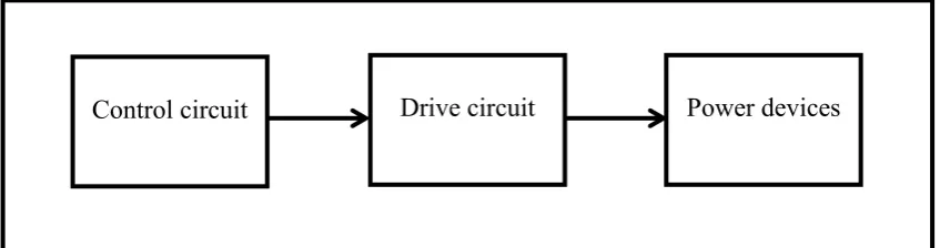
Power electronic drive circuit is an electrical circuit that is constructed to control another circuit or component. This power electronic drive circuit will provide an interface between the control signal (small signal electronics) and power circuit. Figure 2.2 below shows the block diagram of the main part in the power electronic driver [22].
[image:22.595.104.528.438.550.2]
Figure 2.2: Block diagram power electronic driver
2.3.Control circuit
In fact, the circuit driver cannot operate without the presence of control circuit. The control circuit will act as controller whether it is an open loop system or closed loop system. Control circuit with open loop system does not have any feedback attached to the generation of the signal, thus the PWM signal generated only has a constant and precise loop.
Even though open loop system looks simple, but a specific study is needed in order to determine the correct and proper switching technique. Besides, the open loop control circuit does not require much component to compensate the error. For closed loop control circuit, there will be feedback attached to the input signal. Example of feedback control circuit for DC motor are speed, torque and position. To compensate the error for closed loop system there are too many topology needs to be considered of like PI, PD or PID controller. Because of too many feedback topologies discussed before, there will be too many components used to represent the system and thus make it unreasonable for compact design and even though it can recompense for many errors.
Timing of the input signal is in accordance to the desired switching that needed by users such as frequency and duty cycle. But in power electronics there are numerous topology for switching technique even it is an open loop system or closed loop system for example SPWM, square wave technique, wavelet technique, bipolar switching, unipolar switching and many other terms [7].
There are several control circuit that can be propose for this project such as Arduino and XC866 microcontroller. These microcontrollers need to be programmed using C language. The detail about this two microcontroller discussed as below.
2.3.1.XC866-Infineon Technologies
Figure 2.3: XC866 microcontroller [20]
Capture/Compare Unit 6 (CCU6) is included in this XC866. CCU6 is used to generate the pulse width modulated signal with special modes for motor control. 10 bit Analog to Digital converter (ADC) also available for a smoother interface with an analog signal. For low power applications, various power saving modes are readily available for selection by the user. For interrupted handling, Special Function Register (SFR) address range with an intelligent paging has been optimized for usage in this chip.
This XC866 CPU uses a 2-clock machine cycle to allow fast access to ROM or RAM memories without wait state. The instruction sets are divided by 45% one byte, 41% two byte and 14% three byte instructions. It also provides a range of debugging features that include stop/start, breakpoint support, single-step execution read/write access to the data memory, program memory and SFRs[20, 21].
Other features are stated as below;
• Two clocks per machine cycle architecture (for memory access without wait state) • Wait state support for Flash memory
• Program memory download option • 15-source, 4-level interrupt controller • Two data pointers
• Power saving modes
![Figure 2.1: The equivalent circuit of a separately excited DC motor [5]](https://thumb-us.123doks.com/thumbv2/123dok_us/136780.13924/21.595.123.524.70.282/figure-equivalent-circuit-separately-excited-dc-motor.webp)
![Figure 2.3: XC866 microcontroller [20]](https://thumb-us.123doks.com/thumbv2/123dok_us/136780.13924/24.595.175.419.83.235/figure-xc-microcontroller.webp)
