City, University of London Institutional Repository
Citation
: Lu, Y., Kovacevic, A. ORCID: 0000-0002-8732-2242 and Read, M. G. ORCID:
0000-0002-7753-2457 (2018). Numerical study on screw machines with large helix angles. IOP Conference Series: Materials Science and Engineering, 425(1), 012015.. doi:10.1088/1757-899X/425/1/012023
This is the published version of the paper.
This version of the publication may differ from the final published
version.
Permanent repository link:
http://openaccess.city.ac.uk/22439/Link to published version
: http://dx.doi.org/10.1088/1757-899X/425/1/012023
Copyright and reuse:
City Research Online aims to make research
outputs of City, University of London available to a wider audience.
Copyright and Moral Rights remain with the author(s) and/or copyright
holders. URLs from City Research Online may be freely distributed and
linked to.
City Research Online: http://openaccess.city.ac.uk/ [email protected]
IOP Conference Series: Materials Science and Engineering
PAPER • OPEN ACCESS
Numerical study on screw machines with large helix angles
To cite this article: Yang Lu et al 2018 IOP Conf. Ser.: Mater. Sci. Eng. 425 012023
View the article online for updates and enhancements.
1
Content from this work may be used under the terms of theCreative Commons Attribution 3.0 licence. Any further distribution of this work must maintain attribution to the author(s) and the title of the work, journal citation and DOI.
Published under licence by IOP Publishing Ltd
1234567890‘’“”
International Conference on Screw Machines 2018 IOP Publishing IOP Conf. Series: Materials Science and Engineering 425 (2018) 012023 doi:10.1088/1757-899X/425/1/012023
Numerical study on screw machines with large helix
angles
Yang Lu, Ahmed Kovacevic and Matthew Read
City, University of London, Centre for Compressor Technology, London, UK
E-mail: [email protected]
Abstract. Modelling and performance calculation of screw machines with large helix angles such as a single and multiphase screw pumps by use of Computational Fluid Dynamics is challenging. The numerical procedures explained in literature are based on the 3D numerical meshes generated by series of 2D transverse cross sections which allows mesh to either follow the helix or be perpendicular to the rotor axis. This allows generating a conformal mesh. However, if the rotor helix angle is large, the cell skewness becomes prohibitively large which introduces errors in numerical simulation. The paper firstly attempts to generalize the generation method of rotor profiles with emphasis on producing a normal rack and rotors profiles. Then it introduces the method which uses series of 2D numerical meshes in the planes normal to each of the rotors and rack in order to decompose the working domain in two sub-domains. By this means it is possible to achieve 3D numerical mesh with extended capability of mesh refinement in clearances and alignment of the mesh to the main and leakage flows. However, special treatment is required to provide conformal interface between two moving meshes and with the casing. It is expected that it will greatly benefit accuracy and ease of performance calculation using a number of CFD solvers. In addition it is expected that it will allow generation of various different screw machine configurations like single screw machines or machines with conical rotors.
1. Introduction
2
1234567890‘’“”
International Conference on Screw Machines 2018 IOP Publishing IOP Conf. Series: Materials Science and Engineering 425 (2018) 012023 doi:10.1088/1757-899X/425/1/012023
a method using a rack defined in the normal plane to design the twin screw rotor profiles was proposed by him[5]. The advantage of this method is that the normal circular pitch is same for main and gate rotor as the helix angle varies.
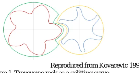
In order to enable performance calculation by CFD, the working domain between the casing and the rotors has to be mapped with a numerical grid. A 3D flow domain between the casing and two rotors is discretized by a number of 2D cross sections. In each of these cross sections, the flow domain is divided in two subdomains for easier grid generation. Practically, three methods can be used to decompose a 2D cross section of the flow domain, namely, differential division line, transverse rack and a normal rack. Kovacevic[6] was the first to use the analytical rack in the transverse cross section for decomposition of the 2D cross section of the flow domain as shown in Figure 1. Recently, as shown by Sham[7, 8], algebraic grid generation is used for a variable profile rotors with parallel axis using transverse rack. In this procedure, the split line is the rack segment stretching between the bottom and top cusp point. In his case, each 2D cross section has a different rotor profile while the position of transverse planes can also vary depending on the lead of the rotors. The two O blocks together form a composite grid. Voorde et al [9]constructed a block structured mesh using similar decomposition but has applied gradient lines and the potential lines in the transverse planes to obtain numerical solution. This often leads to a large gradient of volumes around the CUSP.
In the case of machines with non-parallel axes such as single screw compressors or twin screw compressors with large helix angle, cells formed from the consecutive 2D transverse planes may become too skewed for conservative solution. The large helix angle can cause a twist of the mesh too large for reliable grid generation. Despite a significant increase in the number of papers published recently in the area of grid generation for screw machines, very few journal papers have been published on grid generation of screw machines with large helix angles. In this paper, the proposed normal rack grid generation method will be proposed to decompose the fluid domain using normal planes. Grid Generation in this 2D normal cross section is expected to be much easier and would be directly applicable for screw machines with large helix angles. This paper proposes use of a normal rack in order to separates flow domains of the male and female rotors.
[image:4.595.216.445.475.595.2]Reproduced from Kovacevic 1998 Figure 1.Transverse rack as a splitting curve.
2. Rotor generation
3
1234567890‘’“”
International Conference on Screw Machines 2018 IOP Publishing IOP Conf. Series: Materials Science and Engineering 425 (2018) 012023 doi:10.1088/1757-899X/425/1/012023
It states that two rotors transforming in prescribed motion can generate or envelope each other under necessary conditions.
2.1. Applied coordinate systems
To start the procedure of rotor profiling, the coordinate system must be defined firstly. Single screw rotors and their cutting tools are normally defined in a non-parallel axes coordinate system while the twin screw rotors have parallel axes.
2.1.1. Non-parallel axes coordinate system
The coordinate system of non-parallel and nonintersecting axes is given in Figure 2. The shortest distance between the two axes is C and the angle between them is 𝛴𝛴. Consider coordinate system
𝑆𝑆1(𝑋𝑋1,𝑌𝑌1,𝑍𝑍1) and 𝑆𝑆2(𝑋𝑋2,𝑌𝑌2,𝑍𝑍2) that are rigidly connected to main rotor and gate rotor respectively
and coordinate system 𝑆𝑆1(𝑋𝑋1,𝑌𝑌1,𝑍𝑍1) is the global coordinate system. And the coordinate system
𝑅𝑅(𝑋𝑋01,𝑌𝑌01) rotates around 𝑍𝑍1 with main rotor and the coordinate system 𝑅𝑅(𝑋𝑋02,𝑌𝑌02) rotates around
𝑍𝑍2 with gate rotor, which are local coordinate system. This global and local coordinate systems can be
used to generate the single screw rotors and form cutter profiles from the rotor profiles.
Figure 2. Coordinate systems of non-parallel and non-intersecting axes.
2.1.2. Parallel axis coordinate system.
When the angle between two axes is 𝛴𝛴= 0, the parallel and intersecting axes coordinate system can be obtained and the profiles of main and gate twin screw compressor rotors can be designed and
generated in this coordinate system as shown in Figure 3. 𝑟𝑟1𝑤𝑤 and 𝑟𝑟2𝑤𝑤 are the radii of the pitch circle of main rotor profile and gate profile respectively. So the axes distance is 𝐶𝐶=𝑟𝑟1𝑤𝑤+𝑟𝑟2𝑤𝑤.
4
1234567890‘’“”
International Conference on Screw Machines 2018 IOP Publishing IOP Conf. Series: Materials Science and Engineering 425 (2018) 012023 doi:10.1088/1757-899X/425/1/012023
2.2. Coordinate transformation
With the coordinate system, the matrix of coordinate transformation provide the mathematical methods for generating profiles of the rack from the rotor profiles and conversely, generating the rotor profiles from the rack. With the coordinate systems showed in Figure 2, the coordinate transformation in transition from the main rotor profile coordinate 𝑆𝑆1 to the gate rotor profile coordinate 𝑆𝑆2 is based on the matrix equation:
2
=
M
21 1=
M M M
2p pf f1 1r
r
r
(1)1 1 1 1
1
x
y
z
=
r
, 2 2 2 21
x
y
z
=
r
,1
0
0
0 cos( )
sin( )
0
0
sin( )
cos( )
0
0
0
0
1
pf
C
−
Σ
−
Σ
=
Σ
Σ
M
2
cos( )
sin( )
0
0
sin( )
cos( )
0
0
0
0
1
0
0
0
0
1
p
τ
τ
τ
τ
−
=
M
, 1cos( )
sin( )
0
0
sin( )
cos( )
0
0
0
0
1
0
0
0
0 1
f
θ
θ
θ
θ
−
=
M
Where 𝑟𝑟1(𝑡𝑡,𝜃𝜃) and 𝑟𝑟2(𝑡𝑡,𝜃𝜃,𝜏𝜏) are the generating and generated surfaces respectively and 𝑡𝑡 is a profile parameter while 𝜃𝜃 and 𝜏𝜏 are motion parameters of main rotor profiles and gate rotor profile respectively. 𝑀𝑀2𝑝𝑝 and 𝑀𝑀𝑓𝑓1 are rotational matrices corresponding to rotation with the 𝑍𝑍1 and 𝑍𝑍2 axes respectively and 𝑀𝑀𝑝𝑝𝑓𝑓 is a translational matrix corresponding to the transformation from coordinate system 𝑆𝑆1(𝑋𝑋1,𝑌𝑌1,𝑍𝑍1)to 𝑆𝑆2(𝑋𝑋2,𝑌𝑌2,𝑍𝑍2). Here these matrices are used to generate the rack from the given rotor profiles.
3. Rack generation
5
1234567890‘’“”
International Conference on Screw Machines 2018 IOP Publishing IOP Conf. Series: Materials Science and Engineering 425 (2018) 012023 doi:10.1088/1757-899X/425/1/012023
Figure 4 Rotor profiles of 3/5 and 3/7 with the same rack profile.
3.1. The transverse plane and the normal plane
[image:7.595.191.404.118.245.2]The transverse plane is perpendicular to the rotor shaft. Usually the rotor profiles are generated in the transverse plane. The normal plane is perpendicular to the vector of the helix in the pitch circle. As showed in Figure 5, the transverse plane is indicated by the blue line and the normal plane is indicated by the red line. The angle between the transverse plane and normal plane is the helix angle β. For grid generation, if the transverse plane is used for the grid generation, then the transverse plane is unique for both rotors and rack. However, if the normal plane is used for grid generation, in that case each rotor will have a series of its own normal planes and the rack will have its own normal plane.
Figure 5. Transverse plane and normal plane.
3.2. Transverse rack
The transverse rack can be generated from the main rotor profile. The main rotor profile coordinate in system R(X01, Y01) is 𝑟𝑟1 (x01, y01) and the gate rotor profile coordinate in system R(X02, Y02) is
𝑟𝑟2 (x02, y02). For the parallel axes, since the angle between two axes is Σ= 0, gear ratio 𝑖𝑖 =𝜃𝜃/𝜏𝜏 and
𝑘𝑘= 1 + 1/𝑖𝑖. If the generated rotor profile is the main rotor, the meshing gate profile equations in the transverse plane can be obtained according to the Equation 1 as:
02 01
02 01
cos( )
sin( )
0
0
1
0
0
cos( )
sin( )
0
0
sin( )
cos( )
0
0
0
1
0
0
sin( )
cos( )
0
0
0
0
0
1
0
0
0
1
0
0
0
1
0
0
1
0
0
0
1
0
0
0
1
0
0
0
1
1
x
C
x
y
y
τ
τ
θ
θ
τ
τ
θ
θ
−
−
−
=
6
1234567890‘’“”
International Conference on Screw Machines 2018 IOP Publishing IOP Conf. Series: Materials Science and Engineering 425 (2018) 012023 doi:10.1088/1757-899X/425/1/012023
02 01 01
02 01 01
cos( ) sin( ) cos( )
sin( ) cos( ) cos( )
x x k y k C
i
y x k y k C
i
θ
θ
θ
θ
θ
θ
= + − = − + + (2)Rack coordinates can be calculated from Equation 2 if the gear ratio 𝑖𝑖 tends to infinity:
0 01 01 1
0 01 01
cos( ) sin( )
sin( ) cos( )
r w
r
x x y r
y x y k
θ θ θ
θ θ
= + −
= − +
(3)
The rack can be regarded as the rotor with infinite radius which means the gear ration 𝑖𝑖 tends to infinity. The main rotor profile and gate rotor profile can be generated from the rack profile 𝑟𝑟0𝑟𝑟(𝑥𝑥0𝑟𝑟,𝑦𝑦0𝑟𝑟) respectively as:
01 0 0 1
01 0 0 1
cos( ) ( ) sin( )
sin( ) ( ) cos( )
r r w
r r w
x x y r
y x y r
θ θ θ
θ θ θ
= − −
= + −
(4)
02 0 0 2
02 0 0 2
cos( ) ( ) sin( )
sin( ) ( ) cos( )
r r w
r r w
x x y r
y x y r
θ θ θ
θ θ θ
= − − −
= + −
(5)
[image:8.595.230.379.472.611.2]By solving the meshing equation and the rack profile equations, the transverse rack profile can be obtained. The rack surface between two rotors can be obtained by projecting the transverse rack to the rack normal plane as shown in Figure 6. The rack surface always lies between the main rotor and gate rotor.
Figure 6. Rack surface.
3.3. Normal rack
The normal projection of the rack surface called the normal rack 𝑟𝑟𝑛𝑛𝑟𝑟(𝜃𝜃,𝛽𝛽) can be generated analytically from projecting the rack surface onto the normal plane. The normal rack profile equations are as follows:
7
1234567890‘’“”
International Conference on Screw Machines 2018 IOP Publishing IOP Conf. Series: Materials Science and Engineering 425 (2018) 012023 doi:10.1088/1757-899X/425/1/012023
Where 𝑟𝑟𝑛𝑛𝑟𝑟 is the normal rack profile and β is the helix angle at the pitch circle. The normal rack for the main rotor and gate rotor in the normal plane is as shown separately in Figure 7.
[image:9.595.176.422.151.317.2](a) (b)
Figure 7. Normal rack of (a) main rotor and (b) gate rotor.
4. Domain decomposition
The grid generation process of screw machine is performed in the Cartesian coordinate system introduced at the beginning of the paper and starts from the process of replacing the working chamber with a set of grid points. The decomposition of the flow region between the casing and two rotors consists of dividing the region into a series of 2D cross sections. In practise three methods can be utilised to decompose a cross section of the working domain, namely, transverse differential division curve, transverse rack and the normal rack. So far the grids of the fluid domain are generated in transverse planes. A different method using the normal rack to split the fluid domain in the normal cross section is proposed in this paper. It is more convenient if the main rotor and gate fluid domains are cutting by their normal planes respectively, so the grids can be generated in the normal planes. This process will make the grid lines between the consecutive planes nearly normal to the planes which will completely render or at least reduce the skewness of the grids. The 2D cross sections are then combined together to construct the full 3D fluid domain representing the main and gate fluid domains.
4.1. The fluid domain
8
1234567890‘’“”
International Conference on Screw Machines 2018 IOP Publishing IOP Conf. Series: Materials Science and Engineering 425 (2018) 012023 doi:10.1088/1757-899X/425/1/012023
Figure 8. Two sub-domain between the rotors.
4.2. Decomposition method
[image:10.595.194.377.493.726.2]The fluid domain between the rotors and casing is represented by a number of cross sections using the normal planes of the main rotor and gate rotor respectively. Then the normal rack line and the casing will form the outer boundary of the fluid domain while the rotor profile acts as the inner boundary. Figure 9 shows the sub-domain of the gate rotor cut by 20 consecutive normal planes to show how is the fluid domain changing. The orientation of the profile is aligned with the orientation of normal planes. The fist cross section is cut out at the end of the domain. Following that, the six normal cross sections are identical because the gate and the main sub-domains are apart. Once the two sub-domains interface, the normal rack replaces the outer circle as the outer boundary gradually cutting in and then out after which the domain returns to the shape formed by the outer circle and the rotor. If all of these 2D normal planes are meshed with a numerical grid, then a three dimensional fluid domain can be obtained by combining meshes in two dimensional cross sections. There are many advantages of the domain decomposition in normal planes. Firstly, the meshes in the clearance between rotors and casing can be refined by adjusting the density of nodes in required sections and the alignment of the mesh to the main and leakage flows can be achieved. Secondly, orthogonality of the mesh can be easily obtained. All of this advantages can contribute to a robust and efficient simulation of twin screw machines using a number of CFD solvers.
9
1234567890‘’“”
International Conference on Screw Machines 2018 IOP Publishing IOP Conf. Series: Materials Science and Engineering 425 (2018) 012023 doi:10.1088/1757-899X/425/1/012023
5. Conclusions
In this paper, the analytical racks of screw rotor in transverse plane and normal plane are firstly introduced. Then it introduces a method which uses normal rack to decompose the fluid domain between the twin screw rotors and the casing into two sub-domains in which numerical meshes can be generated in the planes normal to each of the rotors. By this means it is possible to achieve 3D numerical mesh with extended capability of mesh refinement in clearance and alignment of the mesh to the main and leakage flows. This method can also be used in the single screw and non-parallel axis compressors like internal conical rotary screw compressor. Application of the method will be demonstrated in the case of screw machines with large helix angles as used in single and multiphase screw pumps from the simulated and experimental results.
Acknowledgments
This research was supported by China Scholarship Council and the Centre for Compressor Technology at City, University of London.
References
[1] Litvin F L and Fuentes A 2004 Gear Geometry and Applied Theory (New York: Cambridge university press)
[2] Stosic N 1998 On gearing of helical screw compressor rotors Proc. Inst. Mech. Eng. 212 p587 [3] Stosic N and Hanjalic K 1996 General Method for Screw Compressor Profile Generation Int.
Compressor Engineering Conf. at Purdue (West Lafayette, Indiana, USA) pp 157-162
[4] Wu Y and Fong Z 2009 Optimization design of an explicitly defined rack for the generation of rotors for twin-screw compressors Mechanism and Machine Theory44 pp 66-82
[5] Wu Y and Fong Z 2008 Rotor Profile Design for the Twin-Screw Compressor Based on the Normal-Rack Generation Method Journal of Mechanical Design130
[6] Kovačević A 2002 Three-Dimensional Numerical Analysis for Flow Prediction in Positive Displacement Screw Machines Degree of Dorctor of Philosophy In: School of Engineering: (City University London)
[7] Rane S and Kovacevic A 2017 Algebraic generation of single domain computational grid for twin screw machines. Part I. Implementation Advances in Engineering Software107 pp 38-50 [8] Rane S and Kovačević A 2017 Application of numerical grid generation for improved CFD
analysis of multiphase screw machines IOP Conf. Series: Materials Science and Engineering
232
[9] Voode J V, Vierendeels J and Dick E 2004 A grid generator for flow calculationsin rotary volumetric compressors. In: European Congress on Computational Methods in Applied Sciences and Engineering (Finland)