Thyristor Based Modular Multilevel Converter with
Active Full-bridge Chain-link for Forced
Commutation
Peng Li, Stephen J. Finney, Derrick Holliday
Electronic and Electrical Engineering Department University of Strathclyde
Glasgow, G1 1XW, UK Email: [email protected]
Abstract—Voltage source converter (VSC) such as modular multilevel converter (MMC) has been intensively studied for high voltage direct current (HVDC) applications due to its flexible terminal voltage adjustment, compatibility with weak ac grid and independent active/reactive power control over conventional line-commutated-converter (LCC). However, LCC using thyristors still offers advantages such as high current capability and low semiconductor losses, making it dominant in the construction of large scale converter station. This paper investigates the potential of using thyristor to build the MMC sub-module circuitry, where an auxiliary full-bridge chain-link (FB-CL) is adopted for the controlled transition and forced commutation of main thyristor-bridge, forming the proposed active forced commutated (AFC) thyristor cell. The AFC-MMC combines the advantages of LCC and MMC by the hybrid use of thyristor and self-commutated device, including the high power capacity, optimized efficiency, flexible control and enhanced fault-tolerant ability.
Keywords—modular multilevel converter, thyristor, full-bridge IGBT chain-link, forced commutation, high power capacity, low semiconductor losses, dc fault reverse-blocking ability
I. INTRODUCTION
The construction of the high voltage direct current (HVDC) transmission system requires high capacity and fault-tolerant voltage source converters (VSCs) as the enabling technology to achieve reliable and flexible power flow dispatch. Among various emerging VSC candidates, the modular multilevel converter (MMC) achieves best compromise for a wide range of features such as modularity, improved power conversion efficiency, enhanced wave-shaping ability, continuous dc side current, smooth arm current and reduced dc fault transient current to meet the diverse grid requirements for power quality and reliability [1-7]. Also, MMC results in a reduction in total switching actions compared to conventional two-level VSC. Thus, significant gains in conversion efficiency are achieved through the near elimination of the switching loss; and its semiconductor losses are dominantly contributed by the switch conduction losses, which are further dictated by device on-state characteristics [3, 8]. At present, the on-state voltage drop and power capacity of reliable self-commutated power switches such as the insulated-gate-bipolar-transistor (IGBT) are still
uncompetitive compared to thyristor for similar power rating. For example, 4.5kV/1.8kA IGBT T1800GB45A has a typical forward voltage of 3.7V [9]; while taking the 4.8kV/1.77kA thyristor T1551N48TOH as its rival, the on-state voltage is only 1.57V~1.7V [10]. This implies the conduction losses (main contribution of the converter losses) in half-bridge (HB) MMC using IGBT can be roughly up to twice of that in LCC system given the same DC-link voltage and power rating. The latest generation of MMC HVDC converter station has achieved the semiconductor losses below 1%. However, in a hundreds of MW or GW level system, this power losses can be significant (comparable with large power wind turbines) and will require considerable cooling system installation. Hence, in large power HVDC transmission system, thyristor based line-commutated-converter (LCC) remains dominant by its low semiconductor losses but with its inherited weaknesses to be tolerated such as the power flow reversal difficulty in multi-terminal networks and incompatibility with weak ac grid due to lack of reactive power control, etc. [11-13].
HVDC transmission system is vulnerable to dc side pole-to-pole short circuit fault due to the uncontrolled fault current through the freewheeling diodes. In order to offer dc-fault ride through capability to the MMC, several new cell circuit beyond the basic HB cell has been developed such as the full-bridge (FB) module, mixed cell, clamped diode cell and asymmetrical transition cell. However, all these solutions have to result in reduced efficiency performances relative to HB-MMC, which are caused by the increased total semiconductor device number in the conduction paths [2, 6, 8, 14-16].
In an effort to further improve the efficiency of MMC and make it comparable with the conventional LCC, this paper proposes an investigation of active forced commutated (AFC) thyristor cells as its building block. In this way, several of the topological merits of MMC can be maintained including the independent active and reactive power control as in normal VSC; while achieving high power capability and low power losses that are close to LCC. The forced voltage commutation of the proposed cell is ensured by using an auxiliary chain-link (CL) of FB with self-commutated switches (IGBT is assumed) acting as a controlled voltage source and operating for only short period. In this manner, the majority of the power flows
The authors gratefully acknowledge the support from EPSRC grant EP/K035096/1: “Underpinning Power Electronics 2012 - Converters theme”.
through the main thyristor bridge that has very low conduction losses. Also, the dc-fault blocking ability is achieved. Detailed analysis and simulation results for the proposed schemes are presented in later sections.
II. BASIC WORKING LAWS OF THE AFCCELL
The configuration of the proposed AFC cell is depicted in Fig. 1(a), where the series connections of thyristors Q1a and Q2a
are employed as the main power switches with anti-parallel thyristor strings Q1b and Q2b for the current freewheeling under
full range of power factors. The successful commutation of the thyristor-bridge is guaranteed by the active controlled FB-CL that provides reversible voltage to force the current of the thyristor to be zero and turn off. The auxiliary FB-CL is a string of FB modules using self-commutated IGBT, which provides the small amount of power necessary for the thyristor commutation. In this sense, the average power and cooling design of FB-CL can be light and compact without significant impact on the overall efficiency and power density.
In Fig. 1(a), the gate signals of Q1b and Q2b are determined
by the arm current polarity. For example, if the arm current flows out of (into) terminal T2, the anti-parallel device Q1b
(Q2b) sees no gate drive and remain shut down; while Q2b (Q1b)
is kept to be triggered. On the other hand, the main switches Q1a and Q2a are switched by the gate signals coordinated with
the controlled voltage source equivalent of the FB-CL for the forced commutation. If the sub-module blocked dc voltage is noted as VSM. The FB-CL should be designed to have internal
redundancy that facilitates its behavioral voltage trajectory be able to cross the envelope defined by ±½VSM. When the
output voltage of FB-CL is higher (lower) than +½VSM
(-½VSM), the upper (lower) thyristor string can be reliably
turned-off provided its gate signal is removed. The energy balancing of the FB-CL module capacitors inside the proposed AFC cell can be realized by the bipolar voltage generation capability of each FB module in coordination with the voltage sorting results and the load current polarity [17-19].
(a)
[image:2.595.315.554.48.315.2](b)
Fig. 1. Schematic of the proposed converter: (a) AFC cell with reverse-blocking capability; (b) AFC-MMC.
MMC using the proposed AFC cells is shown in Fig. 1(b). It is observed that the AFC cell is able to facilitate dc-fault reverse-blocking (RB) capability due to the use of anti-parallel thyristors. When dc short circuit fault is detected, all the gate signals of thyristors and the FB-CL will be blocked after the forced turned-off processes. In this manner, the total FB-CL capacitor voltage (½VSM) can effectively decay the dc fault
current.
Application of the AFC cell to MMC must consider that the switching delay of normal thyristor is much longer than IGBT (typically hundreds of microseconds); as a result, the cell number and sampling frequency of AFC-MMC should be chosen sufficient low. This requires each AFC cell to block high dc voltage, which can be implemented thanks to the mature and reliable series connection of thyristors. For example, if the turn-off time of the selected thyristor is 200µs, a maximum five-level AFC-MMC blocking the full dc-link voltage up to similar level of LCC can be designed with four cells per arm and around 2ms sampling period in staircase mode, i.e. M=4 in Fig. 1(b). In this way, the signal channels and control complexity of global controller is reduced provided the modulation of each AFC cell is made autonomous. Also, it is noticed the auxiliary FB-CL operates only during the thyristor commutation process (around 10% of each period), leading to a low average power losses and low requirements on its thermal design.
[image:2.595.81.246.480.719.2]efficiency compared to IGBT based MMC. Therefore, although the maximum voltage level number is limited in the AFC-MMC due to the slow switching speed of the high capacity thyristor (larger filter size than IGBT solutions but smaller than LCC), the proposed scheme is still potentially applicable for HVDC transmission systems, where efficiency is paramount.
III. EFFICIENCY PERFORMANCE OF AFC-MMC
The use of the proposed AFC cell has significant influences on the overall conversion efficiency of the MMC. Generally, due to the reduced total switching instances offered by the topological merits, the total semiconductor losses of MMC are dominantly contributed by its conduction part, which can be calculated through the procedures as follows [20]:
• If the dc side current per phase is noted as Id, and Im is
the ac side peak current, the conduction angles α and β
for positive and negative arm current can be determined by (1).
1 1 1
2
1 1 1
2
2
cos ( ) cos ( cos ) 2
cos ( ) cos ( cos ) d m d m I m I I m I α ϕ β ϕ − − − − − = = − = = (1)
• The forward voltage of power switch can be estimated by (2), where VT0 and rT are the on-state voltage with
zero current and slope resistance respectively.
0
T T C T
V
= ⋅ +
r I
V
(2)
• By integrating the instantaneous power of the thyristors over conduction periods, the average power dissipations of the main switches and free-wheeling devices PA and
PB can be obtained by (3), where F represents the total
number of devices in conduction path, φ is the power factor angel and m is the modulation index.
2 2 0 2 2 0 2 2 0 2 2 0
[(2 cos 4 8 cos )
16
(3 cos 8 ) 4 cos ]
[(2 cos 4 8 cos )
16
(3 cos 8 ) 4 cos ]
m
A T m T m T
T m T
m
B T m T m T
T m T
I F
P r I m r I m V
r mI V m
I F
P r I m r I m V
r mI V m
ϕ ϕ α
π
ϕ ϕ
ϕ ϕ β
π ϕ ϕ = + + + + − = + − − − − (3)
• Given the FB-CL conduction losses temporarily being neglected, the total conduction losses of the proposed AFC-MMC can be then estimated by adding the PA and
PB as shown in (4).
2 2
0
2 2
0
[8 cos ( ) 2 cos
16
4 16 4 cos ] m
T T T m
T m T I F
P m V r I m
r I V m
ϕ α β π ϕ
π
π ϕ
= − +
+ + −
(4)
In the proposed AFC-MMC, the total conduction losses are distributed between thyristors and IGBTs (as well as their anti-parallel diodes). In the majority of operation time, the power is dissipated by thyristors; while the IGBTs only conduct during
the commutation period. To keep the simplicity, a weighted coefficient κ is adopted in (5) to combine these two parts and achieve a total conduction loss evaluation for the AFC-MMC. In (5), PI and PD are the IGBT and anti-parallel diode losses
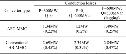
calculated using the same method as in (3) for a conventional MMC [20]. In the proper operation of the AFC-MMC, κ is roughly 0.8~0.9 to guarantee the sufficient loss reduction. A case study using the thyristor and IGBT in Table 1 and κ = 0.9 for the conduction loss comparison under different power factors between the conventional MMC and the proposed converter are shown in Table 2 [8]; and the reduced conduction losses in the AFC-MMC can be observed.
(1
) (
)
= ⋅ + − ⋅
+
con T I D
[image:3.595.323.544.242.309.2]P
κ
P
κ
P
P
(5)
Table 1. Key parameters comparison for thyristor and IGBT at similar switching capacity [9, 10].
Device type Model Voltage rating Current rating On-state voltage
Thyristor T1551N48TOH 4.8kV 1.77kA 1.57~1.7V
[image:3.595.313.552.362.464.2]IGBT T1800GB45A 4.5kV 1.8kA 3.7V
Table 2. Conduction losses of three-phase AFC-MMC and conventional MMC (dc-link voltage: 600kV; ac side line-to-line RMS:300kV; rated
apparent power: 687MVA)
Converter type Conduction losses P=600MW, Q=0 P=0, Q=600MVar P=600MW, Q=300MVar (lagging)
AFC-MMC 1.34MW (0.22%) 1.2MW (0.2%) 1.49MW (0.25%)
Conventional HB-MMC 2.69MW (0.45%) 2.34MW (0.39%) 2.84MW (0.47%)
The switching losses of the converter are related to the total switching instances, which is reduced significantly in MMC compared to two-level VSC. The thyristors of AFC-MMC all experience soft switching processes; while the switching losses contributed from the IGBT part is influenced by the operation mode. If the AFC-MMC is operated in staircase mode, similar level of switching losses is expected as in conventional MMC but at the expense of lowering the wave quality. Practically, the selective harmonic optimization is able to achieve a trade-off between the two aspects of switching losses and harmonic distortions for specific requirement [21].
IV. SIMULATION RESULTS
model in Matlab/Simulink is used considering the latching current, recovery time and other parasitic parameters.
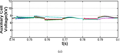
At first, with the power factor set to be 0.99, the resulted key voltage and current waveforms are summarized in Fig. 2. It is observed that the five-level staircase mode voltage waveform is able to be synthesized with the proposed AFC-MMC, and the successful commutation of thyristors can be implemented with output current level reaching 3kA, see Fig. 2(a) and (b). Also, the snapshot of the upper and lower arm currents can be demonstrated by Fig. 2(c), which agrees with the conventional MMC. Fig. 2(d)-(e) represent the capacitor voltage balancing results of the main cell capacitors as well as the auxiliary FB-CL module capacitors by utilizing the redundant switching states of the proposed converter.
(a)
(b)
(c)
(d)
[image:4.595.309.556.60.170.2](e)
Fig. 2. The simulation results of detailed converter model for AFC-MMC with high power factor: (a) converter output voltage; (b) load current; (c) arm currents; (d) sub-module cell voltages; (e) auxiliary chain-link cell voltages.
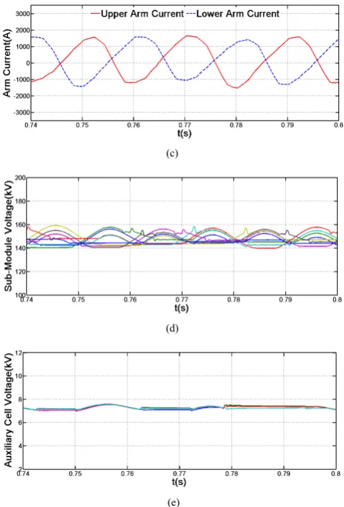
Then, to evaluate the reactive power operation capability of the AFC-MMC, the power factor is adjusted to be 0.2 with lagging reactive power. Similarly, the key waveforms of the converter are displayed in Fig. 3, where the five-level staircase mode voltage waveform of the proposed AFC-MMC is shown as in Fig. 3(a), and the ac side current remains about 3kA but with approximate 80° lagging of the terminal voltage, see Fig. 3(b). In this case, the arm current snapshots are included in Fig. 3(c). Due to the low active power level in this operational case, the dc component current flowing in the arm of the AFC-MMC is decreased significantly compared to that in Fig. 2(c). Fig. 2(d)-(e) verify that both the voltages on the main sub-module cell capacitors and the auxiliary FB-CL module capacitors can be balanced with the cell energy balancing algorithms under lower power factor.
With the results presented in both Fig. 2 and Fig. 3, the proposed AFC-MMC has been verified to be able to offer four-quadrant operation capability.
(a)
(c)
(d)
[image:5.595.38.287.58.425.2](e)
Fig. 3. The simulation results of detailed converter model for AFC-MMC with low power factor: (a) converter output voltage; (b) load current; (c) arm currents; (d) sub-module cell voltages; (e) auxiliary chain-link cell voltages.
In further, Fig. 4 (a) and (b) demonstrate the switching current and voltage waveforms of the thyristor in each cell during its commutation process. It is observed that the thyristor is able to be turned-off through the coordinated operation of the FB-CL, which implies that independent active and reactive power control ability can be achieved as in the conventional VSCs.
In another side, the main thyristors in the proposed AFC cell will experience soft switching processes thanks to the use of the FB-CL for controlled transition. As shown in Fig. 4 (a), the majority of the load current will flow through the low loss thyristors, contributing to an enhanced efficiency performance for the AFC-MMC. However, due to the slow recovery speed of the high capacity phase control thyristors, the wave quality of the converter terminal voltage contains certain amount of low order harmonics, which requires the use of active filtering or the passive tuned filters to meet the grid code.
With the development of the next generation wide bandgap devices such as the silicon-carbide (SiC) technology that offers higher operating temperatures, fast switching on/off capability and low switching/on-state losses, the adoption of high power
fast recovery thyristors is expected to be able to achieve a better compromise on its total semiconductor losses and the output voltage wave quality for the proposed hybrid device based solution. Also, the footprint of the overall converter station can be reduced drastically. Nevertheless, at present, the current capability of commercial SiC thyristors are still not high enough to be applied for high power applications [22].
(a)
(b)
Fig. 4. Zoomed-in version of the thryistor key waveforms: (a) thyristor current waveform during commutation; (b) thyristor voltage during commutation.
V. CONCLUSIONS
In this paper, the active forced commutation (AFC) cell is proposed for modular multilevel converter (MMC) to enhance its power capacity and conversion efficiency by the use of the thyristors for dealing with the main power of the converter. Also, the full-bridge chain-link (FB-CL) with self-commutated devices is employed to operate in short period to implement the forced commutation and transition of the main power switches in each cell.
With the main current carried by the thyristor-bridge and the short period operation of the IGBT part in the AFC cell, reduced conduction losses are obtained due to the lower on-state forward voltage drop of thyristor compared with that in IGBT based MMC.
[image:5.595.307.558.140.392.2]To conclude, the hybrid use of thyristor and IGBT in the proposed approach combines the advantages of conventional MMC and LCC. It is able to achieve a compromise between the converter efficiency and control flexibility, fulfilling a wide range of practical requirements for high power high efficiency applications.
REFERENCES
[1] P. K. B. Jacobson, G.Asplund, L.Harnnart, a. T. Jonsson, "VSC-HVDC Transmission with Cascaded Two-level Converters," in presented at the CIGRE 2010, 2010.
[2] R. Marquardt, "Modular Multilevel Converter: An universal concept for HVDC-Networks and extended DC-Bus-applications," in Power Electronics Conference (IPEC), 2010 International, 2010, pp. 502-507. [3] P. L. T. Jonsson;, S. Maiti; and Y. Jiang-Häfner, , "Converter
Technologies and Functional Requirements for Reliable and Economical HVDC Grid Design," in CIGRÉ Canada Conference, The Westin Calgary,Alberta, 2013.
[4] J. Rodriguez, L. Jih-Sheng, and P. Fang Zheng, "Multilevel inverters: a survey of topologies, controls, and applications," Industrial Electronics, IEEE Transactions on, vol. 49, pp. 724-738, 2002.
[5] K. Ilves, A. Antonopoulos, S. Norrga, and H. P. Nee, "Steady-State Analysis of Interaction Between Harmonic Components of Arm and Line Quantities of Modular Multilevel Converters," Power Electronics, IEEE Transactions on, vol. 27, pp. 57-68, 2012.
[6] A. Nami, L. Jiaqi, F. Dijkhuizen, and G. D. Demetriades, "Modular Multilevel Converters for HVDC Applications: Review on Converter Cells and Functionalities," Power Electronics, IEEE Transactions on,
vol. 30, pp. 18-36, 2015.
[7] S. Debnath, Q. Jiangchao, B. Bahrani, M. Saeedifard, and P. Barbosa, "Operation, Control, and Applications of the Modular Multilevel Converter: A Review," Power Electronics, IEEE Transactions on, vol. 30, pp. 37-53, 2015.
[8] G. P. Adam, K. H. Ahmed, and B. W. Williams, "Mixed cells modular multilevel converter," in Industrial Electronics (ISIE), 2014 IEEE 23rd International Symposium on, 2014, pp. 1390-1395.
[9] IXYS. Power Electronics Products PartDetail. Available: http://ixapps.ixys.com/PartDetails.aspx?pid=6846&r=1
[10] Infineon. Power Semiconductor Products Mannual. Available: http://www.infineon.com/cms/en/product/
[11] R. L. Sellick and M. ; Akerberg, "Comparison of HVDC Light (VSC) and HVDC Classic (LCC) site aspects, for a 500MW 400kV HVDC
transmission scheme," in AC and DC Power Transmission (ACDC 2012), 10th IET International Conference on, 2012, pp. 1-6.
[12] L. Younggi, C. Shenghui, K. Sungmin, and S. Seung-Ki, "Control of hybrid HVDC transmission system with LCC and FB-MMC," in Energy Conversion Congress and Exposition (ECCE), 2014 IEEE, 2014, pp. 475-482.
[13] G. Chunyi, Z. Yi, A. Gole, and Z. Chengyong, "Analysis of dual-infeed HVDC with LCC-HVDC and VSC-HVDC," in Power and Energy Society General Meeting (PES), 2013 IEEE, 2013, pp. 1-1.
[14] G. P. Adam and B. W. Williams, "Half- and Full-Bridge Modular Multilevel Converter Models for Simulations of Full-Scale HVDC Links and Multiterminal DC Grids," Emerging and Selected Topics in Power Electronics, IEEE Journal of, vol. 2, pp. 1089-1108, 2014.
[15] C. Chao, G. P. Adam, S. Finney, J. Fletcher, and B. Williams, "H-bridge modular multi-level converter: control strategy for improved DC fault ride-through capability without converter blocking," Power Electronics, IET, vol. 8, pp. 1996-2008, 2015.
[16] R. Marquardt, "Modular Multilevel Converter topologies with DC-Short circuit current limitation," in Power Electronics and ECCE Asia (ICPE & ECCE), 2011 IEEE 8th International Conference on, 2011, pp. 1425-1431.
[17] G. P. Adam, O. Anaya-Lara, G. M. Burt, D. Telford, B. W. Williams, and J. R. McDonald, "Modular multilevel inverter: Pulse width modulation and capacitor balancing technique," Power Electronics, IET,
vol. 3, pp. 702-715, Sep 2010.
[18] P. Li, G. Adam, D. Holliday, and B. Williams, "Controlled Transition Full-bridge Hybrid Multilevel Converter with Chain-links of Full-bridge Cells," IEEE Transactions on Power Electronics, vol. PP, pp. 1-1, 2016. [19] E. Solas, G. Abad, J. A. Barrena, S. Aurtenetxea, A. Carcar, and L.
Zajac, "Modular Multilevel Converter With Different Submodule Concepts - Part I: Capacitor Voltage Balancing Method," Industrial Electronics, IEEE Transactions on, vol. 60, pp. 4525-4535, 2013. [20] P. Li, "New Types of Voltage Source Converters Applied in Flexible AC
Transmission System Devices," University of Strathclyde, 2015. [21] C. Oates, K. Dyke, and D. Trainer, "The use of trapezoid waveforms
within converters for HVDC," in Power Electronics and Applications (EPE'14-ECCE Europe), 2014 16th European Conference on, 2014, pp. 1-10.