Abstract: The basic aim of the electric power sector is to produce power as when required at the suitable sites, then transmitting and distributing to various load centres or consumers, retaining the quality (sustaining frequency and voltage at stated value) and fidelity of supply at an economical tariff. The primary purpose is to have a brief idea about various power quality advancement techniques and to learn the prospects of various harmonic mitigation methods with a focus on Sinusoidal current control strategy (SCCS). The SCCS is a time domain control strategy established on instantaneous p-q theory. The control strategy has been elaborated here in details and has been implemented using MATLAB 2016A. The results have been given and described in details explaining efficacy of the above control strategy. Since sinusoidal current control strategy is a simple and effective control strategy it has tremendous potential for application in the Distributed Generation oriented system. Further researches can be extended toward application machine learning techniques for the improvisation of control performance of the active power filters.
Keywords : Custom Power Devices, Power Quality, Series Active Power Filter, Sinusoidal Current Control Strategy.
I. INTRODUCTION
T
hese days' consumers are very much aware of receiving quality power; therefore they stand as a challenge before the suppliers for hassle-free power delivery. Although a rich quota of power is produced, still it is tough and questioning for power engineers to harmonizing the multiplying anticipations to draw high quality of power which only be viable through the mitigation of harmonics in power system especially resulted due to nonlinear loads. Utilities have already taken many measurements in this regard however opportunities lies for advancement in power quality (PQ) which is a convoluted idiom and needs to be elucidated. In general, quality of power infers moderate frequency interruption, inadequate amplitude and duration of over and under voltages as well as modest harmonic distortion, poor voltage flickering at the source end, besides diminishing share of phase unbalancing, supply frequency fluctuation, etc. The inadequacy of quality power ultimately results in production fall, damage to appliances, increase in voltage drop,Revised Manuscript Received on September 03, 2019
* Correspondence Author
Rudranarayan Senapati*, School of Electrical Engineering, KIIT, Deemed to be University, Bhubaneswar, India. Email: [email protected]
Rajendra Narayan Senapati, Bhubaneswar, India. Email: [email protected]
intervention with communication lines and many more. The power system devices such as end user appliances, overhead transmission lines, underground cables, transformers, rotating electric machines, and protection systems are harshly concerned for poor voltage quality. To mitigate the voltage related issues, static synchronous series compensator (SSSC) can be considered as one of the most effective solutions, but it has certain demerits [1-2]. They are:
Rectification is not possible.
SSSC has to maintain DC link voltage itself, hence cannot control active and reactive power at the same time. SSSC is more capable to mitigate the voltage related issues
properly but is less reactive towards the current related issues.
Due to many switches and energy storing elements, SSSC becomes bulky.
It is also not economically viable to use SSSC in distributed energy environment.
Therefore the most common harmonic filters were passive harmonic filters where a series inductor and capacitor (form an LC tuned circuit connected across the supply mains) are used for mitigating the harmonic current distortions in power industry. As the shunt passive filter characteristics are determined by the impedance ratio of the source and the shunt passive filter, hence shunt passive filter has the following issues:
As passive filters are installed rigidly in place and the passive elements in the filters have very less therefore the tuned frequency and the size of the filter has a hard chances of change resulting it unsuitable for changing system conditions, i.e., not dynamic in nature (operation is independent of varying load and utility source impedance). The parallel resonance between the system and filter results in amplification of current at harmonics restricting a designer to select tuned frequencies to ensure enough bandwidth in between shifted frequencies and harmonics (odd and even).
The earthed neutrals of star connected banks support a low impedance path for 3rd harmonics resulting magnification in few cases.
Requirement of distinctive protective and monitoring devices.
Passive filters are unsuitable for loads like cycloconverters or power system with inter-harmonics.
Performance Evaluation of 3-Phase Series
Active Filter in a Grid Tied PV-System
employing Sinusoidal Current Control Strategy
Passive filters having negligible control on reactive power limits the increase of load demand.
Size of the filter becomes bulky for THD control resulting overvoltage with the banks are switched in and under voltage with switched out.
It posses resonance problems, system impedance dependency performance, absorption of harmonic current of nonlinear load, etc., further leading propagation of harmonics through the power system.
Apart from that, it is only helpful for the part of the electrical system upstream of the filter connection point, i.e., harmonics continue to flow between the downstream loads and the filter's point of connection limits its use to a few harmonics with a huge chance of introducing resonance further into the power system.
Different active power filters (APFs) are the probable alternative for diminishing the effects emerging because of non-linear loads on the power network which passages to recompense harmonics produced by nonlinear loads. To accomplish compensation, generation of the reference signal signifies the design outcome required for active filter controlling. Somewhat adoption of filters armors electrical appliances that is distorted by low PQ and bypasses the propagation lead to instabilities in the power systems. Many control strategies have been realized, out of which the most effective is sinusoidal current control strategy for mitigation of the harmonics and also others PQ issues as generated due to unbalanced or unstable system owed to the non-linear loading condition [3].
II. ACTIVEPOWERFILTERS(APFS)
APFs as a PQ improvement equipment operate miscellaneous non-linear loads conferring current injection that abort the presence of harmonics current in power system. Further it customizes the power factor through reactive current compensation.
Advantages of an active filter are it can remove all types of harmonic currents from the sensitized non-linear loads, i.e., for lagging loads, it can compensate and behaves as a damping resistor to prevent from harmonic resonance. Also, the capital cost of active filters is low as it requires reduced ampere rating. It also provides other advantages that reduce the PQ issues like reduces the voltage fluctuations, voltage regulation, and load balancing. APFs provide an adaptable answer to various PQ issues penetrating harmonic voltage or current with suitable amplitude and phase angle into the system cancelling the nonlinear load harmonics.
Based on PWM converters APFs are associated in series or shunt to the distribution system. Therefore, according to the connection, there are three types of active filters i.e. shunt active power filter (ShAPF), series active power filter (SAPF) and hybrid power filter (HPF).
The Hybrid power filters (HPFs) are alloy of active and passive filters that assists in appreciable cutback in the rating and expenses over filters. These filters are competent in damping out harmonic resonances rather compensating for harmonic currents only [4-5]. The series hybrid active power filter (SHAPF) are used due to its multitasking features, but it is incapable to handle various PQ issues as a single operating devices, i.e., sags, swells, notches, unbalancing, etc.
The filtering characteristics of ShAPF depend on the source impedance (inductive in nature), more is the source impedance result with better filtering characteristics. Nevertheless, the source impedance should be insignificant at the fundamental frequency to reduce the voltage drop appreciably which can be fascinated by the insertion of series active impedance with the ac source. The active impedance can be realized by the SAPF through the voltage source PWM inverter.
The SAPF performs as administrable voltage source and ShAPF as administrable current source. Both of these designs are executed desirable with VSI, with a capacitor acting as a dc bus.
III. SERIESACTIVEPOWERFILTER(SAPF) The SAF is a series connected device with the power supply used as a voltage booster with its voltage compensation characteristics acts as a constant voltage source (CVS) [6-7]. A single-phase SAF has been designed so as to operate bidirectional avoiding the use of dc capacitor. Furthermore it posses simpler implementation towards hardware control [8]. The SAPF is customarily accustomed to mitigate anomalies in voltage and other PQ problems. They are more adequate in compensating the current issues as compare to shunt compensators.
A. SAPF Configuration
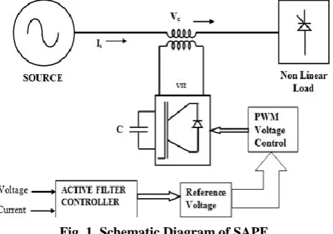
[image:2.595.308.549.425.594.2]The schematic diagram of SAPF has shown in Fig 1; which consists of two components, i.e., PWM voltage control and active filter controller (AFC).
Fig. 1. Schematic Diagram of SAPF
The elemental SAPF voltages are incorporated by the converter with a familiar dc capacitor. The set voltage for this converter is calculated through the AFC presented in Fig 1 has the input signal as load voltage and load current (same as source current).
A PWM voltage controller will be processing power and incorporate the compensating voltage to be depleted from the network. AFC will transform the signal to interpret the real-time instant compensating voltage to pass through continuously to PWM converter. The SAPF operates in a closed loop method sensing the voltage and computes the
instant values of the
reference value c
v for the PWM controller. A voltage source inverter (VSI) has been used in SAPF for its higher efficiency, low initial and compact size. It is acclaimed without any supply rather associated with a capacitor as an energy storing component linked at dc end of the converters for SAPF to perform like a compensator. In supplement, zero average energy interchange among the power filter and the power system is observed.
IV. CONTROLSTRATEGYOFSAPF
The design of the controller for SAPF is not so easy when applied in power system as the supply voltage itself is already unbalanced and/or distorted. The aspects of compensation for the active filter may be determined by the control algorithm as enforced in the SAPF controller.
The 3-φ Four-Wire system recognizes all line currents to be sovereign unlike 3-φ 3-Wire system where both of them are autonomous, i.e., for a 3P4W system,
i
a,i
b,i
care independent to each other whereas for a 3P3W system, among the three currents two of them are independent. There are several reasons for considering the 3-φ 3-wire system. One of the major advantages is the easiness of controlling the line current harmonic values in pq-reference frame, which simply converts 3-φ 3-wire currents and voltages into 2-φ mutually independent quantities, so that easier control is possible in pq-domain.The design of the controller for SAPF is not so easy when applied in power system as the supply voltage itself is already unbalanced and/or distorted. The aspects of compensation for the active filter may be determined by the control algorithm as enforced in the SAPF controller.
The 3P4W system recognizes all line currents to be sovereign unlike 3P3W system as both of them are autonomous, i.e., for 3P4W system,
i
a,i
b,i
care independent to each other whereas for 3-φ 3-wire system, among the three currents two of them are independent.There are several reasons for considering 3-φ 3-wire system. One of the major advantage is the easiness of controlling the line current harmonic values in pq-reference frame, which simply converts 3-φ-3-wire currents and voltages into 2-φ mutually independent quantities, so that easier control is possible in pq-domain.
•
A steady instantaneous source active power•
A sinusoidal source current•
The minimum supply RMS current which transfers energy to load with less loss in the transmission line, i.e., the corresponding source current and voltages are proportional.For non sinusoidal as well as irregular supply voltages, compensation of load voltage is carried by the SAPF assuring for a single optimal compensation only. Hence, according to the choice of preferences the design of the controller for a SAPF is made which is the major cause of inferring sinusoidal current control strategy.
V. SINUSOIDALCURRENTCONTROLSTRATEGY
Sinusoidal current control strategy (SCCS) is based on instantaneous power theory, which is based upon the transformation from abc- frame to αβ0- frame. But the reason for not adopting control in abc- reference frame is that in 3-φ system the 3-phases are mutually dependent on each other, so independent control of the quantities is difficult. To make the control simple, 3-φ quantities are converted into 2-φ mutually independent quantities, so that easier control is possible in pq-domain, which is a stationery reference frame as proposed by H. Akagi. The purpose for choosing this control strategy is its simplicity in implementation. So far several applications on this strategy have been seen in different literatures. For a system with multiple renewable energy systems integrated, implementing a robust control becomes cumbersome, as the control of renewable itself requires a lot of complexities [9-11].
The control involves 3-φ quantities first converted into 2-φ quantities. Then these 3-phase quantities are used to evaluate the instantaneous powers in time domain, both instantaneous active as well as reactive power can be estimated. By using low pass filter, the harmonic power can be extracted, which is accustomed with the generation of compensating current with the known zero sequence power. The neutral point clamped capacitor voltage can be used to evaluate the zero sequence power. Hence the above mentioned method is termed as sinusoidal current control strategy (SCCS) as the compensating current is sinusoidal in nature.
Advantages of pq-Theory over all other compensating theory are it can be valid for both steady state as well as transient state. Instantaneous power can be defined on αβ0-frame i.e. in three phase form. So, three phase system can be considered as a single unit but not the addition of three individual 1-φ circuits. abc- frame to αβ0- frame transformation is also known as Clarke transformation.
For appropriate expression, zero sequence power, p0 is expressed in terms of αβ0- frame of reference, as the instantaneous watt power, p and instantaneous VAR power, q are known from the instantaneous power theory.
Mathematically:
(1)
β i i 0 i
v v
0
v v 0
0 0 0 v
q p 0 p
Here, the 3-φ instantaneous active power is defined by both instantaneous active power with the instantaneous zero sequence power. In case of 3-φ 3-wire (3P3W) system, instantaneous zero sequence power does not exist so for this type of system, P3-ϕ can be treated as p only. But for 3-φ-4-wire (3P4W) system it may be noted as follows:
) 2 ( 0 0 0
3 vaiavbibvcic v i v i v i pp
P
(3) 3 vi vi
P Whereas,
(4)
P ower Active the of Component g Oscillatin ~ P ower Active the of Value Average
p p
p
From (4), it is observed that instantaneous active power can be divided into two parts i.e.,pandp~, where pis referred to the average value or dc value of active power which implies total energy transfer in the system and ~p defines the oscillating component of active sequence power and the instantaneous reactive power can be defined as:
(5)
vabic vbcia vcaib 3 1 i v i v
q
Where,
i
a,i
b,i
candv
a,
v
b,
v
care the instantaneous current and voltage in abc frame, whereasi
,i
,i
0 and0
,
,
v
v
v
are the instantaneous current and voltage in 0
frame.
As the converters used now a days are basically acts a non-linear load, the energy flow between the systems has a boundary condition. Comparing to the response of the converter and the generation of harmonic components and reactive power with the traditional mode, the analysis of different type of power is not sufficient using average or rms value as variables. So in a nonlinear circuit, time domain analysis has to be carried out for analysis of energy flow.
A 3-φ sinusoidal voltage which consists of only positive and zero sequence voltages are considered for the realization of zero sequence power. Symmetrical component in frequency domain only is applicable for steady state operation. Hence it can be converted into time domain for analysis of both steady state and transient state. For voltage, (6) is used as follows:
(6) ) 0 v θ t sin( 0 V 2 ) v θ 3 2π t sin( V 2 c v ) 0 v θ t sin( 0 V 2 ) v θ 3 2π t sin( V 2 b v ) 0 v θ t sin( 0 V 2 ) v θ t sin( V 2 a v
Whereas (7) used for current is as follows:
(7) ) 0 i θ t sin( 0 I 2 ) i θ 3 2π t sin( I 2 c i ) 0 i θ t sin( 0 I 2 ) i θ 3 2π t sin( I 2 b i ) 0 i θ t sin( 0 I 2 ) i θ t sin( I 2 a i
In order to obtain zero sequence components, the above equation is required to be converted into αβ0-frame by using Clarke transformation. For voltage, (8) is used as follows:
) 8 ( ) 0 sin( 0 6 0 ) sin( 3 ) sin( 3
v t V v v t V v v t V v Whereas (9) used for current is as follows:
) 9 ( ) 0 sin( 0 6 0 ) sin( 3 ) sin( 3 i t I i i t I i i t I i
From (8) and (9), the instantaneous zero sequence power can be obtained as:
) 10 ( 0 ~ 0 ) 0 0 2 cos( 0 0 3 ) 0 0 cos( 0 0 3 p p p i v t I V i v I V
p
So the instantaneous zero sequence power can be divided into two parts which consists of average power and oscillating component of power which is at double the line frequency. Here
0
p is unidirectional energy flow as conventional active power and
0 p
~ represents the oscillating component whose average value is zero. Interesting fact about zero sequence power is p0cannot be obtained alone without the oscillating component ~p0. Hence the total zero sequence components always associated with both average as well as oscillating component [12].
In the case of pq-theory, the instantaneous power so obtained is in time domain without consideration of the rms value of voltage and current. It also comprises of conventional frequency-domain concept for which the theory is not the contradictory theory rather it is the complementary theory in frequency domain.
The instantaneous zero sequence power components in the elemental voltage and current or in harmonics have no impact on instantaneous watt power and reactive power. The total instantaneous watt power is always same as the addition of instantaneous true power and zero sequence power that includes both average and oscillating components. The instantaneous reactive power reveals the energy exchanged between system even in the harmonic and unbalance condition.
[image:4.595.50.290.489.637.2]The physical implication of instantaneous power in αβ0-frame has been illustrated in Fig 2.
Fig. 2. Physical implication of instantaneous power in αβ0-frame
o p
p Total Instantaneous unit-time power flow.
q Exchange of Power between 3-phases with zero energy transfer.
As shown in Fig 2, the total instantaneous active power flow and instantaneous imaginary power flow in between the two systems, i.e., source and load for a power distribution system. Imaginary power shows the energy exchanged between the phases not the
and var current units are obtained from the instantaneous abc voltages and currents are represented as:
(11) Part Reactive Part Active q 0 α v β v β v α v 2 β v 2 α v 1 0 p α v β v β v α v 2 β v 2 α v 1 β i α i
With the use of Inverse Clarke Transformation abc real and imaginary current may be obtained as follows:
(12)
β v α v 2 β v 2 α v β i β v α i α v 2 3 2 1 2 3 2 1 0 1 3 2 c( p) i b( p) i a( p) i And ) 13 ( ab v ca v bc v 2 ca v 2 bc v 2 ab v b i ca v a i bc v c i ab v c( q) i b( q) i a( q) iWhereas
v
ab,
v
bc,
v
caare the line voltages which can be obtained as follows:a v c v ca v , c v b v bc v , b v a v ab
v
Also c( p) i , b( p) i , a( p)
i and
c( q) i , b( q) i , a( q)
i are the real and
imaginary current components which generate real and imaginary power respectively.
The line voltage does not contain any zero sequence
component as: 0
ca v bc v ab
v .
As the line voltage is free from zero sequence components, hence (12) and (13) can be re-written as:
(14)
c( q) i b( q) i a( q) i c( p) i b( p) i a( p) i 0 i 0 i 0 i c i b i a iAmong the two classifications of instantaneous power theory, one of them has already been described, i.e., instantaneous pqtheory. The other one is instantaneous
abc theory where use of Clarke transformation (abcto
0
transformation) is avoided. In this process instead of calculating real and imaginary power, active and non-active current is computed from abc phase voltage and currents [13]. A. SCCC for SAPF
As there is a question over the selection of the SAPF, then few reasons can be broadly listed as:
•
It is hard to comprehend a large-rating PWM converter with swift current respond and low loss in compensating the harmonic components with high efficiency as in the main circuit of ShAPF.•
Injected currents by ShAPF may flow into the capacitors connected on the power system.Apart from the above, SAPF compensates the current distortions resulted due to non-linear loads with an appointment of high impedance path (by the voltage generation of equal frequency of same current harmonics to be waived) enforcing the high frequency current to pass
through the passive filter in parallel.
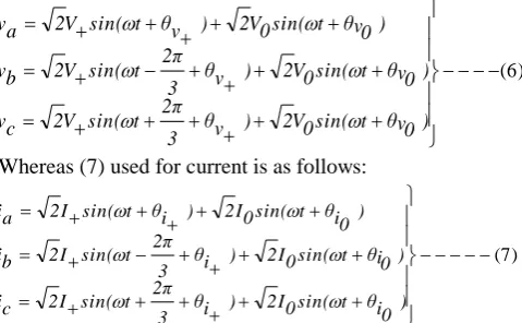
[image:5.595.310.544.126.313.2]Based on the above discussions the proposed work is once again carried out with the simple control strategy on instantaneouspqtheory on SAPF, which is applied on a 3P3W system. The basic block diagram of a 3P3W SAPF for compensation of voltage is illustrated in Fig 3.
Fig. 3. Basic block diagram of 3-P-3-W SAPF The SAPF is for compensation of voltage. The input for the control block meant for calculation of the instantaneous power is the phase voltages at the PCC and the line currents of the nonlinear load for compensation.
Assuming no zero-sequence current, the relation among the source voltage, load voltage and active filter voltage is given by, ) 15 ( Cc v Cb v Ca v c v b v a v sc v sb v sa v
The basic SAPF voltages are synthesized by three 1-Φ converters with common dc capacitor. The reference voltage for these converters is computed by the AFC as per Fig 3. Here the voltages are calculated by the dual pqtheory (assuming the known current component, real and the complex powers though which the voltage components to be calculated) as given in (16):
(16) β v α v 0 v α i β i 0 β i α i 0 0 0 0 i q p 0 p F rom the above equation, the oscillating real power~pand the oscillating imaginary powerq~,assuming the zero sequence powerp0and~p0are to be zero due to zero-sequence current. With these oscillating powers, the instantaneous voltages to be injected by the SAPF for load harmonic voltage compensation by using:
(17) ~ ~ q p α i β i β i α i 2 β i 2 α i 1 Cβ v Cα v
A certain amount of pshould be added to p~ with an objective to compensate the
voltages Ca v and
Cb
v can be converted to the abcreference by:
(18)
Cβ v
Cα v
2 3 2 1
2 3 2 1
0 1
3 2
Cc v
Cb v
Ca v
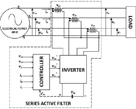
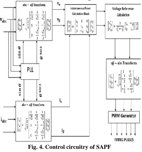
[image:6.595.47.286.59.147.2]The SAPF generates the voltages mentioned in (18) for the harmonic voltage compensation in the load producing oscillating active and reactive power at the load end. This approach confirms the voltage from the source side have purely sinusoidal waveforms. The control block diagram of the SAPF has been illustrated in the Fig 4.
Fig. 4. Control circuitry of SAPF The voltage
Cabc
[image:6.595.51.291.220.478.2]v are the voltage that needs to be obtained for compensating the harmonic component of load, which produce the oscillating real and reactive power. The source and load voltages thus obtained are purely sinusoidal in nature.
Fig. 5. System Block Diagram for SAPF
Fig 5 illustrates the SAPF based detailed modelling of grid connected renewable system.
The SAPF integrated to the system that is implemented to take care of power quality related issues and to inject grid as well
as load desired power. It consists of a PV system whose voltage is stepped up by a boost converter.
VI. SIMULATIONANALYSIS
To validate the efficacy of the suggested sinusoidal current control strategy through SAPF the simulation was carried out on a 3P3W system for non-linear load. The proposed strategy was simulated using MATLAB/SIMULINK 2016a with a system having Intel Core i5 processor with clock frequency 2.4 GHz, 8 GB RAM. The analysis of SAPF was carried in different environments.
The load parameters considered for the simulation are given in the Table I.
Table I: Load Parameter
Parameter Value
Load Resistance 60Ω
Load Inductance 0.15mH Grid Voltage 230 V (RMS) DC Link Capacitance 2000µF
PV Voltage 104V
The simulation was carried out as per the system model given in Fig 5 and the control strategy explained in Fig 4.
The Fig 6(a) represents the performance of supply considering the SAPF. This SAPF is resulting source voltage characteristic in phase and the Fig 6(b) presents the performance of the source current of a 3φ3W system. It is observed that the sinusoidal current control strategy in series active filter maintains sinusoidal behavior of source voltage while load voltage harmonics is compensated.
(a)
(b)
Fig. 6. (a) Source Voltages, (b) Source Currents Because of nonlinear load (i.e., RL rectifier circuit) the load voltage was found to be distorted and unbalanced in absence of compensation, but applying
[image:6.595.312.540.419.689.2] [image:6.595.48.284.554.709.2]balanced and smooth as shown in Fig 6 (a) and 6 (b). The circuit breakers (CB) were a given a time delay of 0.1 sec to see the actual performance before the inception of the SAPF into the circuit. The non-linear behaviour of the load giving rise to distortions can be seen during the first 0.1 second. After this, due to the effect of SAPF on the system the balanced and distortion free voltage can be observed. These waveforms disclose the compensation of SAPF for the disturbances at the source end.
The Fig 7 (a) and (b) show the load voltage and current waveforms respectively. The load voltage was found to have 231 V RMS value and load current is found to be having an RMS value of 3.53 RMS value.
(a)
[image:7.595.311.543.88.222.2](b)
Fig. 7. Load End Parameters: (a) Load Voltage (b) Load Current
[image:7.595.51.291.211.467.2]Due to the application of Sinusoidal current control strategy the load voltage and current waveforms are found sinusoidal. Further the strategy is applied to variable grid voltage condition to see the performance of series active filter compensation. The figure 8 shows the grid voltage at different instances.
Fig. 8. Grid injected voltage
There is voltage sag between 0.5 sec to 1 sec and voltage swell in between 1.5 sec to 2.0 sec. But the series active filter able to maintain the voltage level fixed at 311V RMS. The injected voltage by the series inverter is shown in the above
figure.
The load voltage is fixed due to the voltage injected by a SAPF which can be observed in the Fig 9.
Fig. 9. Load voltage
The injected voltage adds up to grid voltage during 0.5 sec to 1.0 sec and nullifies during 1.5 sec to 2.0 sec. Here it is found that the response of the SAPF is quite fast and it tries to maintain the desired load voltage by injecting the compensating voltage.
[image:7.595.304.548.323.443.2]The series injected voltage at the series transformer terminals is presented in Fig 10.
Fig. 10. Series inverter injected voltage
There was an injection of voltage during voltage sag from 0.5 seconds to 1 second. From 1.5 second to 2 seconds there was an interruption, taken care by SAF by injection of voltage during the same period.
[image:7.595.305.547.534.686.2]The harmonic analysis of load voltage is obtained as seen in the Fig 11.
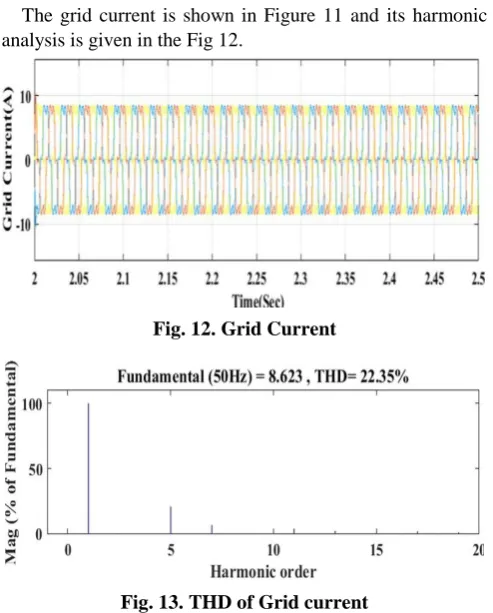
[image:7.595.48.292.582.726.2]The grid current is shown in Figure 11 and its harmonic analysis is given in the Fig 12.
Fig. 12. Grid Current
Fig. 13. THD of Grid current
The THD in grid current was found to be 22.35%. The RMS value of grid current was 8.623 A. Presence of 5th order harmonics has been suppressed by SAF significantly. Its magnitude in respect of fundamental is found to be below 20 %.
The SAF based on sinusoidal current control strategy offers assurance against voltage sag and swell. Besides this, it offers harmonic isolation to load voltage, as evident from the results. The THD in load voltage is found to be 0.74 percent which is quite satisfactory. The performance of series active filter can be validated by comparing the performance of some other techniques proposed by other authors, which is given in the Table II.
Table II: Validation Table for Series Active Filter
Author Proposed Methodology Grid Voltage THD
Wang et al. [14] Hybrid control approach based on reference generation
5.7% Kim et al. [15] Shunt Active filter with LCL
Filter
1.37% Proposed
Sinusoidal Current Control Strategy
Sinusoidal Current Control Strategy applied to Three Phase Three Wire Strategy
0.74%
VII. CONCLUSION
The conceptual analysis of SAPF, by sinusoidal current control strategy has been executed for 3P3W system along with passive and non-linear load. Even the voltage and current in 3-Φs are jeopardise towards the disturbance in the transient state, the adopted control strategy provokes drawing of steady current during steady state loading conditions. The load voltage at load terminal was obtained sinusoidal and balanced irrespective of sag, swell.
REFERENCES
1. Senapati, Rudranarayan, Rajesh Kumar Sahoo, Sonakshi Pradhan, and Rajendra Narayan Senapati. "Sinusoidal current control strategy for 3-phase shunt active filter in grid-tied PV system." In 2017 International Conference on Energy, Communication, Data Analytics and Soft Computing (ICECDS), pp. 1272-1277. IEEE, 2017.
2. Ghosh, Arindam, and Gerard Ledwich. Power quality enhancement using custom power devices. Springer Science & Business Media, 2012. 3. Mauricio Aredes, Jurgen Hafner and Klemens Heumann, "Three-Phase Four Wire Shunt Active Filter Control Strategies," IEEE Transactions on Power Electronics, Vol. 12, No. 2, pp. 311-318, March 1997. 4. F.Z. Peng, H. Akagi, A. Nabae, “A new approach to harmonic
compensation in power systems-a combined system of shunt passive, series active filters”, IEEE Trans. Ind. Appl., Vol. 26, no. 6, pp. 983–990, 1990.
5. D. Detjen, J. Jacobs, R. W. De Doncker & H. G. Mall, “A new hybrid filter to dampen resonances and compensate harmonic currents in industrial power systems with power factor correction equipment”, IEEE Transactions on Power Electronics, vol. 16, no. 6, pp. 821-827, 2001.
6. M. Z. EL-Sadek, E. A. Ibrahim & R. M. Kamel, “Series active filter for voltage harmonic suppression and 50HZ voltage boosting”, in Power Systems Conference, MEPCON 2006. Eleventh International Middle East, Vol. 1, pp. 59-64, IEEE, 2006, December.
7. M. Aredes and E. H. Watanabe, “New control algorithms for series and shunt three-phase four-wire active power filters”, IEEE Transactions on Power Delivery, Vol.10, No. 3, pp. 1649-1656, 1995.
8. G. Buticchi, D. Barater, C. Concari & G. Franceschini, “Single-phase series active power filter with transformer-coupled matrix converter”, IET Power Electronics, Vol. 9, No. 6, pp. 1279-1289, 2016. 9. Senapati, Rudranarayan, Rajesh Kumar Sahoo, Rajendra Narayan Senapati, and Prafulla Chandra Panda. "Performance evaluation of Sinusoidal current control strategy unified Power Quality Conditioner." In Electrical, Electronics, and Optimization Techniques (ICEEOT), International Conference on, pp. 1404-1408. IEEE, 2016.
10. Senapati, Rudranarayan. "Study and Analysis of Performance of 3-Phase Shunt Active Filter in Grid-tied PV-Fuel Cell System Employing Sinusoidal Current Control Strategy." International Journal of Renewable Energy Research (IJRER)8, no. 1 (2018): 67-81. 11. Senapati, Rudranarayan, Senapati, Rajendra Narayan, Moharana,
Manoj Kumar, Panigrahi, Chinmoy Kumar.” A Comparative Study of Shunt Active Power Filter and Unified Power Quality Conditioner under Sinusoidal Current Control Strategy in Grid Connected Mode.” In
International Journal of Applied Science Engineering & Management (IJASEM), 3 (6), 2017: 11-26
12. Senapati, Rudranarayan, Rajendr Narayan Senapati, and Manoj Kumar Moharana. "Sinusoidal Current Control Strategy for UPQC in Grid Connected PV-Fuel Cell Microgrid." International Journal of Engineering and Technology 9, no. 4 (2017): 2800-2813
13. Senapati, Rudranarayan, Rajendra Narayan Senapati, Prashnajit Behera, and Manoj Kumar Moharana. "Performance analysis of unified power quality conditioner in a grid connected PV system." In Signal Processing, Communication, Power and Embedded System (SCOPES), 2016 International Conference on, pp. 416-420. IEEE, 2016.
14. Wang, Z., Wang, Q., Yao, W., & Liu, J. (2001). A series active power filter adopting hybrid control approach. IEEE Transactions on Power Electronics, 16(3), 301-310.
15. Kim, Y. S., Kim, J. S., & Ko, S. H. (2004). Three-phase three-wire series active power filter, which compensates for harmonics and reactive power. IEE Proceedings-Electric Power Applications, 151(3), 276-282.
AUTHORSPROFILE
Rudranarayan Senapati received his B.E. degrees in Electrical Engineering from Indira Gandhi Institute of Technology (IGIT), Sarang, Odisha, India, under Utkal University in 2001 and M. Tech degree in Communication Systems Engineering, from
KIIT
working as Assistant Professor in School of Electrical Engineering, KIIT University since 2005.
He has many national and international publications in his name. He has also reviewed many research papers.
His current research interests include grid integration of renewable energy sources, power quality conditioners, power quality control and analysis, smart grids and micro grids, distributed generations, solar forecasting, electric vehicles. He is also having a keen interest over electric vehicles and solar forecasting .