Abstract: This research article gives a detailed insight of the design, simulation of a compact circular shaped microstrip patch antenna that is fed using a coplanar waveguide feed (CPW for practical wireless communication applications). The antenna is typically designed for Ultra wideband (1.46-6GHz), Bluetooth (2.4GHz), ZIGBEE (2.4GHz), WLAN (5.15- 5.35 GHz and 5.725- 5.825), Wi-Fi (2.4-2.485GHz) and HIPERLAN-2(5.15 - 5.35 GHz and 5.470 -5.725GHz) wireless applications with stop band characteristics for the H (partial C band). The proposed antenna has an overall packaged structure dimensions of 78 x75 x1.605 mm3 and is fabricated on FR4 substrate as a circular patch antenna with a coplanar ground .The commercially available laminate FR4 substrate that is used has a dielectric constant of 4.4, height of 1.6mm and a loss tangent of 0.0024.The prospective antenna shows a simulated impedance bandwidth of 4.54 GHz. The coplanar waveguide feeding used with this antenna helps in improving antenna performance in terms of its impedance bandwidth as this geometry helps in creating multiple current loops at the antenna structure, thereby exciting nearby frequencies that merge to show a broadband of operation. The antenna’s operational bandwidth is also improved by the concept of modified ground, in which triangular and rectangular shapes are added symmetrically on both sides of ground plane that provide a better fringing effect and hence an improved bandwidth.
Index Terms: CPW fed, modified ground structure (MGS), ultra wide band (UWB), CST MWS version 2017.
I. INTRODUCTION
An ever-growing demand for high data rate in the current wireless applications, has led researchers to pay attention towards designing broadband and ultra-wideband antennas that can support a higher data rate (that has to be transmitted or received). Additionally, almost all wireless handheld devices demand the antennas to be compact, small sized and conformable to matching and un-matching surfaces. Microstrip patch antennas satisfy these properties and are therefore a preferred choice as they are easy integratable with RF circuits [1, 2]. A major drawback with conventional MPA of low bandwidth has been overcome by researchers through the use of techniques like using thick substrates [3], fractal geometries [4], stacking [5], Defected ground structures (DGS) [5, 16], circular shaped patches [6], slots in MPA [7], using coplanar waveguide feeding (CPW) [8] and use of EBG
Revised Manuscript Received on July 02, 2019.
Gagandeep Kaur, EED, Thapar Institute of engineering and technology, Patiala, Punjab.
Amanpreet Kaur, EED, Thapar Institute of engineering and technology, Patiala, Punjab.
.
structures for improving the pass band and stop band characteristics of the microwave antennas. Since a compact and planar antenna is of interest for RF handheld devices, the current research article aims at the design and testing of a circular CPW fed patch with a modified ground that exhibits a simulated fractional bandwidth of 0.61 at center frequency of 3.1 GHz. The designed antenna structure is planar and it can be easily unified with wireless communication devices for ultra-wide band, Bluetooth, Zig - Bee, C band WLAN Wi-Fi, HIPERLAN-2[11] applications.
II. ANTENNA STRUCTURE AND PARAMETER
OPTIMIZATION
A. Antenna Structure
A higher bandwidth is the demand for current wireless systems to provide a good data rate, antennas with wider bandwidth are required at the transmitter as well as receiver side to support this data rate. Therefore the aim of the proposed antenna design is to obtain an ultra-wide band operation from a conventional circular MPA by using a coplanar Wave guide feeding with a modified ground structure. Since circular patches offer a broader bandwidth and a circular polarization, a circular geometry is preferred for the current antenna design. Coplanar wave guide feeding is integrated with the circular patch geometry since it provides a uni-planar structure to the antenna along with its bandwidth improvement [9, 14], (by allowing loosely bound fields on the antenna surface). Additionally, the CPW feeding technique offers many advantages over other types of feeding techniques like possessing a low dispersion loss, low radiation outflow, capability to control the characteristic impedance and the easy incorporation with active devices [10, 12, and 13]. In order to improve impedance matching between the supply cable and the feed line of the proposed circular CPW antenna, two rectangular and triangular slots are added on the upper sides of the CPW ground plane symmetrically on both the sides of feed line. These improve the impedance bandwidth of operation. Figure 1(a) depicts the front view of the presented CPW fed circular patch antenna. Here a circular monopole patch of radius 20mm (R) is designed with a coplanar ground plane on a rectangular FR4 sheet of dimensions (Ls × Ws) 78 × 75mm2 and a height of 1.57mm.
The feed line that is supplying power to the patch has an optimized length of 3.66 mm to attain characteristic impedance of 50 ohms. The optimization results for feed-line are mentioned in figure 2 in
the next subsection. In order to get an optimum
A Circular Coplanar Waveguide Fed Microstrip
Patch Antenna with Modified Triangular Ground
for UWB Applications
171
Published By:
Blue Eyes Intelligence Engineering Retrieval Number: I10280789S19/19©BEIESP
electromagnetic coupling between the feed line, ground and the antenna, the void between feed line and the coplanar ground planes is optimized to a dimension of 0.57 mm and the results are shown in figure 3 of next subsection.
To further improve the operational pass band and stop-band characteristics of this ultra-wide band antenna; the coplanar ground structure is modified from a conventional rectangular design and two triangular slots of dimensions 16mm, 14mm and 7.07mm are cut from the sides of the coplanar ground symmetrically . Further improvement in impedance matching at the pass band is achieved by adding a triangle and rectangle to the reduced coplanar ground symmetrically on the top at both the sides of the coplanar ground.
The designed antenna structure allows us to achieve a simulated impedance bandwidth of 4.54 GHz from 1.46 to 6 GHz. All the simulations and optimization of the antenna designs are carried out using CST MWS version 2014. The labeled dimensions are mentioned in table 1.
[image:2.595.68.264.276.509.2](b)
Fig.1 Front view of proposed antenna
Table1: Values of optimized Antenna Parameters
IV. PARAMETRIC OPTIMIZATION OF ANTENNA
B. Effect of feed line variation
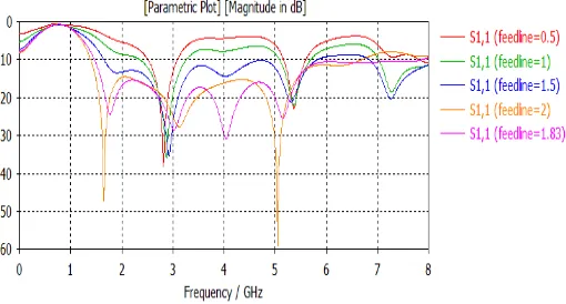
Antenna feed line energizes the patch by supplying power to it. Since it is connected to the supply mains, it controls the drive point impedance of the antenna and affects the Electromagnetic coupling to the slot. Therefore feed line width is optimized to achieve desired antenna performance of the proposed antenna for an impedance matching of 50 ohms. The parametric results (in terms of S11 variation with
[image:2.595.310.565.296.433.2]frequency) for different widths of feed line shown in figure 2. The best optimized results are obtained for a feed line width of 1.83 mm. It is observed that a thinner feed line couple more EM radiations to the antenna since a feed line with lesser width presents a better impedance matching with the antenna in figure 2.
Fig. 2 Parametric variation of feed line width
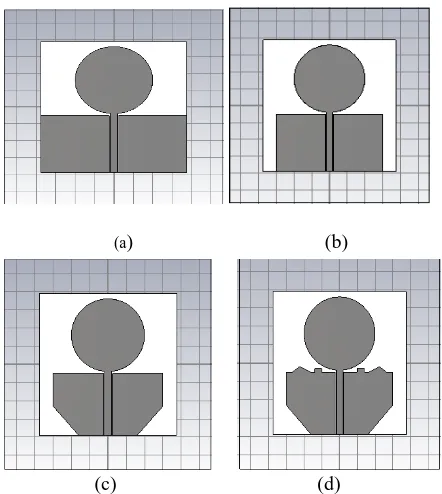
C. Effect of variation in coplanar ground plane In order to optimize the results in terms of impedance bandwidth at the pass band of the antenna’s operation, certain parametric variations were carried out in the coplanar ground structure. To start with, a full rectangular ground was chosen with the patch structure shown in figure 3(a). It was observed that the impedance matching was not satisfactory at the desired pass band of operation and was ranging from1.39-2.53GHz and 2.54 to 8 GHz as shown in figure 4(Design 1). Since a stop band is desired for the H band from this antenna, a reduction in ground length (by 7.5mm symmetrically) on the X axis was done, as shown in figure 3(b). This led to a better impedance matching and hence a broader pass band of antenna was obtained (1.39-4.53GHz) as shown figure 4 (Design 2). In order to achieve an ultra-wide band performance for the desired pass band; two triangular slots are further removed from the sides of the coplanar ground layer as shown in figure 3(c) , these excite resonant frequency near 4.8 GHz and lead to further improvement in the bandwidth as shown in figure 4 (design 3). An improvement in impedance matching (reduction in the value of S11) at the new excited frequencies is also achieved
by further adding triangular and rectangular sections of metal at the top periphery of the ground layer as depicted in figure 3(d) (Design 4).Figure 4 shows the combined plot of all these parametric variations .The
markers at each plot show the band that is excited by
Parameter Values(mm)
Ls 79
Ws 75
R 20
Lf 37
Wf 3.66
W 27.6
g1 18
g2 16
the respective parametric variations. Since geometry of 4(d) shows best results in terms of ultra-wide band operation for the pass band of 1.46 - 6 GHz and a stop band for the X band frequencies, this is the selected optimized geometry for the current research work presented in this article.
(a) (b)
(c) (d)
Fig 3. Parametric variations on the CPW ground (a) Antenna design 1(b) Antenna design 2 (c) Antenna design 3
(d) Antenna design 4
III. SIMULATED RESULTS
The antenna proposed here is designed and simulated with a full wave EM tool i.e. CST Microwave Studio version 2014 software. This tool is based upon the Maxwell’s equations in differential form; all the simulations are carried out in the time-domain solver with perfect open boundary conditions. The hexahedral mesh settings and for an accuracy level of -40 dB have been chosen for antenna simulation. This section presents the simulated results of the proposed antenna in terms of its impedance bandwidth, broadband Gain, Radiation pattern.
A. Simulated impedance bandwidth
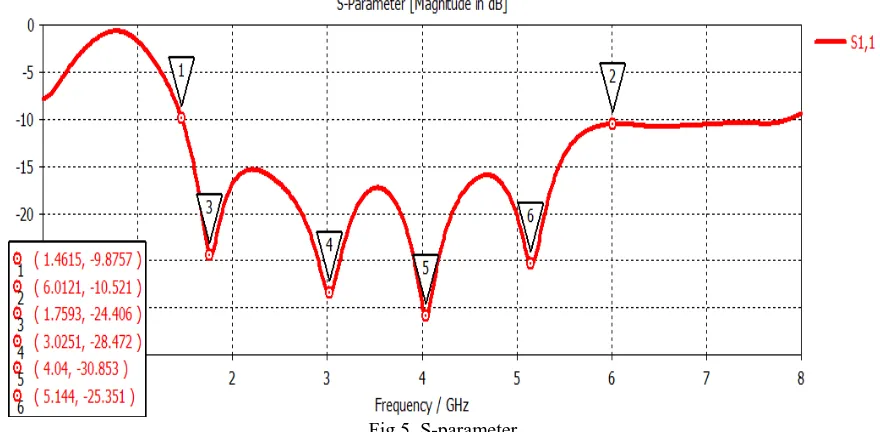
Figure (5) shows the Impedance bandwidth plot of the antenna with S11 (dB) plotted on Y-axis and frequency (GHz)
on X-axis. The antenna is matched to a feed line impedance of 50 ohms at the drive point. The proposed antenna covers an impedance bandwidth of 4.54 GHz from 1.46 GHz to 6 GHz. The simulated pass band of the antenna shows an ultra-wide band with peak return losses of -24.40 dB,-28.47 dB,-30.85 dB and -25.35 dB at resonant frequencies of 1.759 GHz, 3.025 GHz, 4.04 GHz and 5.144 GHz respectively.
This allows the proposed antenna to be suitable for ultra-wide band (1.46 to 6.07 GHz), Bluetooth (2.4GHz), Zig-Bee (2.4GHz), C band (3.7 - 4.2 GHz), WLAN (5.15- 5.35 GHz and 5.725- 5.825 GHz), HIPERLAN-2 (5.15 to 5.35 GHz and 5.470 to 5.725 GHz).
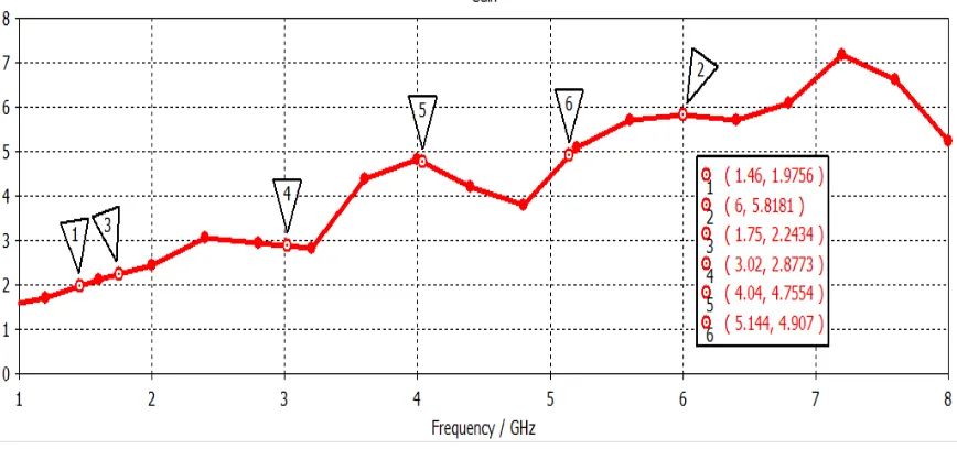
[image:3.595.55.276.118.365.2]B. Simulated gain
Figure 6 shows the broadband operating gain for the proposed CPW fed circular antenna. It is seen from figure 6 that the antenna has a peak gain of 5.81 dB at 6 GHz. The antenna shows an overall average gain of approximately 4dB for the desired pass band of operation. This allows it to be suitable for short range wireless applications of interest. The radiation patterns of proposed antenna design at resonant frequencies of 3.05GHz, 4GHz, 5.07GHz as depicts in figure 7(a), 7(b) and 7(c) respectively. Figure 7(d) shows the radiation pattern at 6GHz i.e. highest peak gain of 5.81dB.
(a) (b)
[image:3.595.305.548.199.535.2](c) (d) Fig 7 . 3D Radiation pattern
V.CONCLUSION
This research article presents a compact and a simple coplanar waveguide fed circular patch antenna. The antenna shows a pass band and stop band characteristics, thus behaving like a microwave filter for the desired band of operation. The measured pass band of the antenna shows an impedance bandwidth of 2.607 GHz at the center frequency of 3.1GHz. This allows the antenna to be well suitable for wireless applications like ultra-wide band (1.46 to 6 GHz),Bluetooth (2.4GHz), Zig-Bee (2.4GHz),C band (3.7 - 4.2 GHz),WLAN (5.15- 5.35 GHz and 5.725- 5.825 GHz),HIPERLAN-2 (5.15 to 5.35 GHz and 5.470 to 5.725GHz). The proposed CPW fed antenna was optimized for the desired pass band by varying its parameters like feed line, ground plane, gap between feed line and ground. This antenna exhibits stop band
173
Published By:
Blue Eyes Intelligence Engineering Retrieval Number: I10280789S19/19©BEIESP
monopole geometry with CPW feed allows the antenna to achieve these ultra-wide band characteristics because CPW feed provides some advantages like low dispersion losses, low radiation outflow,
capability to control the characteristic impedance and the easy incorporation with active microwave devices. Since the antenna presents a simulated average gain of approximately 4dB for the entire from1.46 to 6 GHz, it can be easily used for short range wireless applications like WLAN, Bluetooth for short range indoor wireless applications.
REFERENCES
1. J. Y. Sze and K. L.Wong ,Bandwidth enhancement of a microstrip line-fed printed wide-slot antenna, IEEE Trans. Antennas Propag, Jul. 2001;49(7),pp. 1020–1024.
2. H. G. Schantz , A brief history of UWB antennas , IEEE Aerosp. Electron. Syst. Mag., April 2004 ; 19(4), pp. 22–26.
[image:4.595.93.505.175.379.2]3. Suvadeep Choudhury ,Effect of Dielectric Permittivity and Height on a Microstrip-Fed Rectangular Patch Antenna, International Journal of Electronics & Communication Technology, March 2014;5 (2),pp.129-130.
Fig 4. Combined plot of different antenna geometry
[image:4.595.76.516.421.637.2]Fig 6. Broadband antenna gain
4. Amanpreet Kaur, Rajesh Khanna, and Machavaram Kartikeyan, A
Stacked Sierpinski Gasket Fractal Antenna With A Defected Ground Structure For UWB/WLAN/Radio Astronomy/STM Link Applications, Microwave And Optical Technology Letters, December 2015; 57(12),
pp. 2786-2792.
5. Amanpreet kaur, Rajesh Khanna and Machavaram kartikeyan ,A multi layer dual wideband circularly polarized microstrip antenna with DGS WLAN/Bluetooth/Zigbee/WiMAX/IMT band applications, International Journal of Microwave and Wireless Technologies , 2015;9(2), pp. 317-325.
6. Mohamaed Nabil Srifi, Symon K. Podilchak, Mohamed Essaaidi, and Yahia N. N. Antar , A planar circular disc monopole antennas using compact impedence matching networks for ultra wide band (UWB) applications, IEEE Trans Antennas Propag , 2009 ,782-785.
7. X. Qing and Z. N. Chen, Monopole-like slot UWB antenna on LTCC, in Proc. IEEE International Conference on Ultra-Wideband, 2008, pp. 121–124.
8. S. Cumhur Basaran , Dual wideband CPW fed split ring monopole antenna for WLAN applications, IEEE Trans. Antennas Propagation, 2010; 978(1) ,pp. 174- 177.
9. Kirti Vyas and P. K. Singhal , Bandwidth Enhancement in CPW Fed Compact Rectangular Patch Antenna, International Journal of Electronic and Communication Engineering, 2014; 8(2): pp. 378-381. 10. M. Bod and M. M. S. Taheri , Compact UWB printed slot antenna with
extra Bluetooth, GSM, and GPS bands, IEEE Antennas Wireless Propag. Lett 11(2012), 531–534.
11. C.-L. Tsai and C.-L. Yang. Novel compact eye-shaped UWB antennas, IEEE Antennas Wireless Propag Lett 11(2012), 184–187.
12. Y. Sung, UWB monopole antenna with two notched bands based on the folded stepped impedance resonator, IEEE Antennas Wireless Propag. Lett 11(2012), 500–502.
13. S. R. Emadian, C. Ghobadi, J. Nourinia, M. Mirmozafari, and J. Pourahmadazar , Bandwidth enhancement of CPW-fed circle-like slot antenna with dual band-notched characteristic, IEEE Antennas Wireless Propag Lett 11(2012), 543–546.
14. Dhirgham K. Naji,Compact Broadband CPW-fed Taper-shaped Monopole Antenna with L-slots for C-band Applications, International Journal of Electromagnetics and Applications ,2013; 3(6), pp. 136-143. 15. A. Kaur , R. Khanna and M.V. Kartikeyena , A Stacked Rectangular
MSA with Defected Ground Structure for IEEE 802.11b/g Bands and Wi-Max Applications, International Conference on Microwaves, Antenna Propagation and Remote Sensing (IEEE), 2014, pp. 266–270. 16. Gagandeep Kaur and Amanpreet Kaur, Design of a Slotted Micro-strip
patch Antenna with DGS for an UWB applications, International conference on advancements in engineering and technology, 2017, pp. 39-41.
AUTHORS PROFILE
Gagandeep Kaur received her degree of B.Tech. in Electronics and Communication Engineering in 2015
from University College of Engineering Patiala . She completed her M.E. in Electronics and Communication Engineering with specialization in ultra-wideband microstrip patch antennas in 2017 from Thapar University Patiala, India. She is currently perusing PhD. in Microwave Imaging using ultra-wideband microstrip Antennas from Thapar University Patiala. She has published one paper in international conference and one paper in a Scopus indexed journal.
Amanpreet Kaur was born in Udhampur (Jammu and Kashmir), India. She received her B.E. in Electronics and Communication Engineering degree from Jammu University in 2004. She got her M.E. degree in 2006 and PhD degree in 2016 (specialization in Microstrip Antennas for Wireless communications) from Thapar University, Patiala, India. She is working as an Assistant professor at Thapar University since 2006. Her research interests include Wireless Communication systems (MIMO Systems), Microstrip Antennas for wireless Communication systems and Microwave imaging of human tissues. She has guided 25 M.E. thesis and has handled projects worth Rs 25laks. She is also a life member of IETE (Institution of Electronics and Telecommunication Engineers).She has twenty research papers in international journals and conferences and Five publications in SCIE journals. She is also the member of the editorial board team for the journal entitled “Recent Advances in Electrical & Electronic Engineering” Member of Editorial board for the journal.