Copyright
Biomedical Integrated Circuit Design
for
An Electro-Therapy Device
A Thesis Presented in Partial Fulfilment of The Requirements for The Degree of
Doctor of Philosophy
in
Electronics and Computer Engineering (Bioelectronics)
at
School of Engineering and Advanced Technology Massey University, Albany Campus, New Zealand
by
Ibtisam Abbas
Full name(Ibtisam A. Abbas Al-Darkazly)
ii
In the name of God
Most Gracious, Most Merciful
Dedication
To my parents, whose boundless love and belief in me, from the core of my being, empowered me to be the woman that I am.
To my lovely children and to my talented kids, Zain, Taim and Yoseph, whom are the light in my life.
iii
Abstract
A biomedical integrated circuit design (IC) is utilized for the development of a novel non-invasive electro-therapy device, for low frequency multi-channel biomedical stimulation to transform immune activity and induce anti-viral state. Biomedical integrated circuit design is an important branch of modern electronic engineering that uses the application of electronic engineering principles for biomedical disciplines, to develop bioelectronics devices that are implanted within the body and for non-invasive devices to improve patient’s lives. These devices use the application of an electric field to stimulate reactions to restore normal cell functions and activate the cells to treat a variety of disorders or disease conditions. Bioelectronics devices can be designed for use as alternative treatments to overcome the deficiencies of several conventional medical treatments. It could potentially assist as drug-free relief when therapeutic drugs become ineffective, costly, with serious side effects and cannot be replaced, loss of future treatment options, and hence, life threatening, as for drug resistant Human immunodeficiency virus (HIV-1) patients.
Since the underlying mechanisms of the biological system and disease state is dominated by electrostatic interactions, specifically, the interaction between HIV-1 and the host cell that is predominantly by electrostatic interactions (protein charge-charge interaction) has an important role in its life cycle replication. At given pulses, the charge distribution and polarization of the electro-active protein molecules takes place, inducing conformation change which can enhance immune activity and inhibit the interaction of HIV-1 and host cells, disturbing its life cycle, leading to the mechanisms of the inactivation signal-induced virus death. These electrically induced protein transformations is used in this research as blood-cell treatment and as anti-HIV-1 electrotherapy.
iv
between the electronic signal and the biological cells, and how electronic devices and circuitry directly communicate with the electro-active body tissue and blood cells. This research project addresses the design and development of a novel energy-efficient miniature biomedical device using a new CMOS technology. It can generate, deliver and control an appropriate periodical low frequency electrical pulses, through the low-resistance skin surface to a patient’s blood. The notable feature of such a smart device is its cellular specificity: the parameters of the generated electrical pulse which are designed and selected in order to stimulate only one particular type of tissue (blood) leaving the others unaffected. The device comprises a mixed-signal low power dual-band waveform generator (WFG) chip along with a novel two dual-band tuning system. It was fabricated using Global Foundries (GF) 8RF-DM 130-nm CMOS process with a supply voltage of ±1V for the analog circuit and +1V for logic circuits. The WFG core (band I) can be tuned in the range 6.44 kHz - 1003 kHz through bias current adjustment, while a lower frequency (band II) in the range 0.1 Hz to 502 kHz can be provided digitally. Two WFG approaches, that comprise relaxation oscillators with different relaxation timing networks, have been developed for comparison.
Since the aim of this work is to transfer electrical signal in a specifically controlled fashion through the tissue, a novel low power active electrode-pair signal delivery system, compatible with human skin with high signal integrity, is developed. The circuit was fabricated in a 130-nm CMOS process using a low supply-voltage of +1.2V to deliver bi-phase square waveform signals from 16 selectable low-frequency channels. The individual active electrode can also be used to deliver mono-phase square/triangular waveform output signals. Accuracy, safety, low power, light-weight, miniature and low-cost characteristics are the main concerns. Being a miniature bioelectronics component with low power consumption, the proposed device is suitable both as a non-invasive and as an implantable biomedical device, in which WFG and electrodes circuitry can communicate with the electro-active biomolecule, strongly stimulating certain events in a complex biological system.
v
response to cellular signals. The frequency-dependent dielectric present in proteins involves the redistribution and alignment of the proteins charged molecule and its polar molecule in response to an applied external electrical field can also induce conformation change. Interference polarization within proteins could interrupt the interaction between both sides of predominantly host cell proteins and of the HIV-1 infective envelope and its protein particles. This could disturb the signalling proteins for cell activation, and, hence, the virus cannot conjugate with the target cells and control the host cell protein activity. Since the virus is unable to reproduce out of a host cell, hence the virus cannot mutate and develop resistance easily, and use alternative binding and entry mechanisms as in the pharmacological approaches. After carefully studying the interaction of the HIV-1 virus and the host cell, with respect to signal transfer, CD4 receptor, co-receptors CCR5 and nuclear transport factor nucleoporins FGNup153 proteins of the lymphatic system, which are essential targets for HIV-1 infection and its life cycle replication represent an attractive target to investigate in this research project. The activities of the underlying mechanism of the target cell are then examined utilizing immunofluorescence microscopy technique with specific fluorescent labelled antibodies, and accurate results are obtained with relatively low cost. The results demonstrated that the low frequency electrical pulse could inhibit virus attachment and fusion. It is also could provide a permeability barrier, that prevents the import and export of large macromolecule virus particles through the nuclear pore complex. These effects could induce an antiviral state for a period of time, and stope HIV-1 virus replication, with no potential risks and harm to the host cells, compared to the common drugs. This is promising for the conception of HIV-1 treatment in vivo. Although further investigations are required in order to fully use the application of electrical stimulation in vivo for treatment, the result is provides the necessary impetus for the applications of low frequency electrical stimulation on human immune response. This might offer important antiviral therapy against the most devastating pathogens in human history.
vi
Acknowledgments
The compilation of this research project would not have been possible without the support of others which is sincerely appreciated and thankfully acknowledged. Foremost, I would like to acknowledge and thank my supervisor Dr. Rezaul Hasan, for his valuable guidance, kindly encouragement and scholarly advice at various stages throughout my study. I would like to thank my supervisor Dr. Rezaul Hasan once again for facilitating the funding of this work through Massey University.
I would like to acknowledge the Massey University for financial support for the funding of this work. I also would like to acknowledge the Massey University Human Ethics Committee, Dr. Brian Finch, Human Ethics Chairs' Committee and Director, Mr. Jeremy Hubbard, Human Ethics Chairs' Committee: Southern A and to Ms. Patsy Broad, team leader. I would like to mention the facilities in the laboratory of Human Nutrition, School of Food and Nutrition (SoFN) laboratories, College of Health at Albany campus, Massey University for in-vitro biological tests as part of this work. I am grateful to Dr. Pamela Von Hurst co-director of vitamin D research center for her keen interest in supporting the researcher and her prompt kind encouragement regarding lab facilities and safety. I would further like to thank Dr. Cath Conlon for providing me with a place in the Human Nutrition lab. I thank Mr. James Connell compliance support officer and Mr. PC Tong and Mrs. Rachel Liu for the use of lab facilities and for the health and safety induction in lab building 27 and lab building 10. I also thank profusely Dr. Peter Flanagan, National Medical Director, New Zealand Blood Service for providing a Blood sample. I also would like to acknowledge chip fabrication support from MOSIS.
I would like to thank the staff at School of Engineering and Advanced Technology for their support during my study. I thank Mr. Joe Wang for electronic lab facilities and Mr. Roukin Dmitri for the use of Linux programme. I also would like to thank my friends and colleagues for all of the valuable words of encouragement. I would further like to thank my thesis proof reader, Mrs. Diana Hibbert.
vii
Table of Contents
Abstract………... iii
Acknowledgements………. vi
Table of Contents……… vii
List of Abbreviations……….. xii
List of Symbols……… xiv
List of Figures………. xv
List of Tables………... xxiii
Chapter 1. Introduction ……… 1
1.1 Biomedical Integrated Circuit Design ……… 1
1.2 Relevance……….. 6
1.2.1 Virus Replication………. 7
1.3 Develop Concept ……….. 10
1.4 Research Goals……….. 16
1.5 Scope of This Study……….. 16
1.6 Thesis Overview……… 20
Chapter 2. Overview of The System Model, Theory, Design and Approaches 23
2.1 Introduction………... 23
2.2 Waveform Generator Overview……… 24
2.3 Basic Theory of Oscillator……… 26
2.3.1 Oscillators Approaches……… 28
2.3.2 Relaxation Oscillator Architecture………. 30
2.4 Hysteresis Schmitt Trigger Concept………. 30
2.5 Principles of Operation of Typically WFG Circuit……….. 33
2.5.1 Theory of WFG Based on RC Network……….. 33
2.5.2 Theory of WFG Based on Integrator………... 35
2.6 Waveform Generator Approaches………. 36
2.6.1 Relaxation Timing Network Approaches……… 46
2.6.1.1 Passive RC Approaches……….. 46
viii
2.7 Tuning Circuit Approaches………... 53
2.8 Digital Model for Frequency Divider……… 55
2.8.1 Frequency Divider Theory……….. 56
2.8.2 Flip Flop Approaches……….. 57
2.8.3 Sources of Power Dissipation In A Digital Model………….. 64
2.9 Active Electrode……….... 67
2.10 Conclusion………. 70
Chapter 3. Design Criteria, Implementation and Fabrication of Waveform Generator Circuit for Extra Low-Frequency CMOS Micro- Power Applications …...... 72
3.1 Introduction………... 72
3.2 Trade-off of Low Power CMOS WFG Design Analysis……….. 73
3.3 Design Criteria of CMOS ELF WFG Circuit……… 79
3.4 Circuit Design and Topology of The ELF WFG………... 81
3.5 Circuit Operation of The ELF WFG………. 82
3.6 Simulation and Performance Analyses of The ELF WFG……... 88
3.6.1 Amplitude Control of The ELF WFG………. 91
3.6.2 Frequency Control of The ELF WFG………. 94
3.7 Layout and Fabrication of The ELF WFG……… 96
3.8 Experimental Results of The ELE WFG………... 102
3.9 Conclusion………. 104
Chapter 4. Design Criteria, Implementation and Fabrication of Dual-Band CMOS Waveform Generator With Ultra-Wide Low-Frequency Tuning Range……….. 106
4.1 Introduction………... 106
4.2 Design Criteria of CMOS Dual-Band WFGINT………. 108
4.3 Circuit Design and Topology of The WFGINT……….. 111
4.3.1 WFGINT Circuit Design………... 111
4.3.2 Hysteresis Schmitt Trigger Circuit of The WFGINT……….... 112
ix
4.3.4 WFGINT Circuit Operation………. 117
4.3.5 Components Sizing for Low Power & Low Frequency WFGINT Design………... 121
4.4 Frequency Tuning Technique……… 125
4.4.1 Analog Tuning Model………. 125
4.4.2 Digital Model Implementation……….... 126
4.4.2.1 Clock and Clock_Bar………. 126
4.4.2.2 The Frequency Division Circuit………. 126
4.4.2.3 Multiplexors And Path Selector……… 128
4.5 Simulation and Performance Analyses Of WFGINT……….. 132
4.5.1 Robustness of The WFGINT Circuit………. 135
4.5.1.1 Temperature Variation………... 135
4.5.1.2 Eye Diagram Analysis……… 135
4.6 Simulation Results of The Digital Model……….. 137
4.6.1 Clock And Clock_Bar………. 139
4.6.2 FD circuit………. 140
4.7 Layout and Fabrication of The WFGINT………... 146
4.8 Experimental Results of The WFGINT……….. 150
4.8.1 Amplitude Control of The WFGING……….... 154
4.8.2 Frequency Control of The WFGING………. 155
4.9 Optimization Flowchart of The WFGING………. 159
4.10 Comparison of The WFGINT With ELF WFG and With Other Published WFG……….. 161
4.11 Conclusion……… 163
Chapter 5. Design Criteria, Implementation and Fabrication of a Low- Power CMOS Active-Electrode-Pair For Low-Frequency Multi- Channel Biomedical Stimulation………... 165
5.1 Introduction……….. 165
5.2 Design Criteria for Active Electrode……… 169
x
5.3.1 Active Electrode Circuit Analysis………... 171
5.4 Simulation And Performance Analyses of The Active Electrode………... 174
5.5 Layout and Fabrication of The Active Electrode………. 178
5.5.1 Experiment Results of The Active Electrode……….. 180
5.6 Conclusion……… 185
Chapter 6. In Vitro Biological Experiment Design And Performance To Investigate The Effect of Low Frequencies Electrical Pulses on The Human Blood Cells……….. 186
6.1 Introduction……….. 186
6.2 Chemokine Receptor CCR5………. 189
6.2.1 CCR5 Protein Structure………... 190
6.3 The Nuclear pore complex (NPC)……… 193
6.4 Frequency–Dependent Polarization………. 202
6.5 In Vitro Biological Tests……….. 205
6.5.1 Materials and Procedure……….. 205
6.5.2 Electrical Simulation Procedure……….. 207
6.5.3 Immunofluorescence Microscopy Assay……… 208
6.5.3.1 Immunofluorescence Cell Staining Procedure………... 209
6.6 Electrical Stimulation Results……….. 214
6.6.1 Expression of CD4 and CCR5………. 214
6.6.2 CCR5 N-Terminal Conformation Epitopes………. 216
6.6.3 Distribution of FGNup153……….. 218
6.7 Discussions on Experimental Results………... 223
6.8 Conclusion……… 229
Chapter 7. Conclusion……… 231
7.1 Summary……….. 231
7.2 Contributions of This Doctoral Research………. 243
7.3 Recommendations for Future Research………... 246
xi
Appendix A. Supplementary Documents 282 Ethic Approval 283 List of Publications 284
xii
List of Abbreviations
AA Amino Acid
Ab Antibody
D Aspartic Acid
BJT Bipolar Technology
BSA Bovine Serum Albumin
CCII Current Conveyor
CFOA Current Feedback Operational Amplifier
Clk Clock
Clk_bar Clock_bar
CM Current-Mode
CSE Clocked Storage Element
D-FF D-Flip Flop
DRC Design Rule Checking
ELF Extra Low Frequency
FBS Fetal Bovine Serum
FD Frequency Divider
FF Flip Flop
FG Phenylalanine-Glycine
h Hour
HCl Hydrochloric acid
HIV-1 Human immunodeficiency virus
IC Integrated Circuit
Kap Karyopherin
LVS Layout Versus Schematic
mAbs Monoclonal Antibodies
min Minute
MLF Moderate Low Frequency
MUX Multiplexer
NES Nuclear Export Signal
NLS Nuclear Localization Signal
xiii
NPC Nuclear pore complex
Op-Amp Operational Amplifier
OTA Operational Trans-conductance Amplifiers
PFA Paraformaldehyde
PG Pass Gate
PIC Pre-Integration Complex
PS Path Selector
PVT Process And Temperature Variation
Q Glutamine
SC Stratum Corneum
SDL Schematic-Driven Layout
ST Schmitt Trigger
STG Stage
TG Transmission-Gate
TGFF Transmission-Gate Flip Flop
VTC Voltage Transfer Characteristic
WFG Waveform Generator
WFGINTG Waveform Generator Based on Integrator Timing Network
xiv
List of Symbols
A Area Meter Square C Capacitor Farad Cox Gate oxide capacitance Farad gm Trans-conductance Microampere/microvolt W Channel width of the MOSFET Micro-meter L Channel length of the MOSFET Micro-meter Output resistance of MOSFET Ohms Electron mobility Meter square/Volts seconds Bias Current of MOSFET Microamperes DC Drain current of MOSFET Microamperes VC Capacitor Voltage Output Volts VDD Positive Supply Voltage Volts VINT Integrator Voltage Output Volts Vo Output Voltage Volts VSS Negative Supply Voltage Volts Gate-source voltage of MOSFET Volts − Lower Threshold Voltage Volts
xv
List of Figures
Figure 1.1: Schematic diagram representing the development of a variety of implantable and non-invasive biomedical devices in the real world. These devices use the application of an electric field with an appropriate electrical signal and specific waveform and frequency to be applied internally or externally to a particular area of the body, to treat a variety of disorders or disease conditions, and to improve patients’ lives……… 5 Figure 1.2: The primary protein structure, (a) amino acid structure, and (b)
amino acids are connected together by a covalent linkage called a peptide bond to form polypeptide polymer chains and to build up
the primary structure of a protein……… 10 Figure 1.3: The development and design steps of electro-therapy concept and
device of this research project, (a) block diagram, and (b) Schematic diagrams………
15 Figure 2.1: Block diagram of a simple positive feedback system………. 27 Figure 2.2: Schematic diagram of a simple oscillatory system………. 27 Figure 2.3: Schmitt Trigger, (a) basic Schmitt trigger circuit and (b) voltage
transfer characteristic of the Schmitt Trigger………. 31 Figure 2.4: Comparison between the output voltage transfer characteristic of
the comparator and the hysteresis Schmitt Trigger circuit, (a) comparator response to noisy signal, and (b) hysteresis Schmitt Trigger response to noisy signal………. 32 Figure 2.5: A basic block diagram of a typical WFG circuit, based on a RC
relaxation timing network………... 34 Figure 2.6: A basic block diagram of a typical WFG circuit based on a
hysteretic Schmitt Trigger and an integrator relaxation timing
network………... 35 Figure 2.7: Waveform generator architectures based on, (a) single
differential N-MOSFET OTA, (b) two differential N-MOSFET
OTAs………... 41
xvi
comparator……….. 42 Figure 2.9: WFG architectures based on one OTA and a two-stage
comparator……….. 42
Figure 2.10: WFG architectures based on a dual output DO-OTA, using two single-ended commercial CA3080 OTA ICs………..
43 Figure 2.11: WFG architectures based on (a) three CMOS OTAs, (b) using
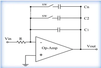
three commercial available LM13600 ICs……….. 44 Figure 2.12: Op-Amp-RC integrator (a) first order Op-Amp-RC Integrator,
(b) digitally controlled switched-capacitor matrices for tuning the
time constant of the Op-Amp-RC integrator circuit………... 49 Figure 2.13: Gm-C integrator (a) first order integrator, (b) a lossy integrator… 50 Figure 2.14: Resistive tuning techniques, voltage controls a bank of
MOSFETs………... 53
Figure 2.15: Schematic diagram of the frequency divider for “divide-by-2”
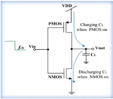
(/2) frequency division circuit with its waveform output………... 56 Figure 2.16: Schematic diagram of the logic gate (a) a simple PMOS and
NMOS pass transistor and (b) a CMOS transmission gate and its logic symbol………... 63 Figure 2.17: Schematic diagram of dynamic switching power dissipation in
CMOS inverter……… 64
Figure 2.18: Types of electrodes: (a) passive electrodes, and (b), active electrode, using commercial Op-Amps with Ag/AgCl transducer for biomedical applications………. 68 Figure 3.1: Trans-conductance amplifier (a) a single common source
MOSFET transistor operating in the saturation region as a current source, (b) the small-signal model……….. 74 Figure 3.2: CMOS Operational trans-conductance amplifier, (a) schematic
diagram (b) the small signal model of the differential amplifier with a current mirror load………... 77 Figure 3.3: Proposed, ELF WFG. Based on the periodical charging and
discharging operation of the capacitor C, ELF WFG circuit, provides a periodical square waveform output signal at Vo and an
xvii
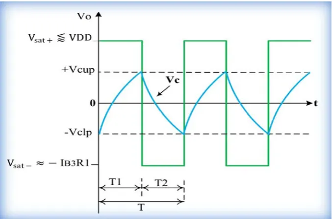
Figure 3.4: Waveforms in the proposed ELF WFG……….. 83 Figure 3.5: Simulated transient output waveforms for ELF WFG for the first
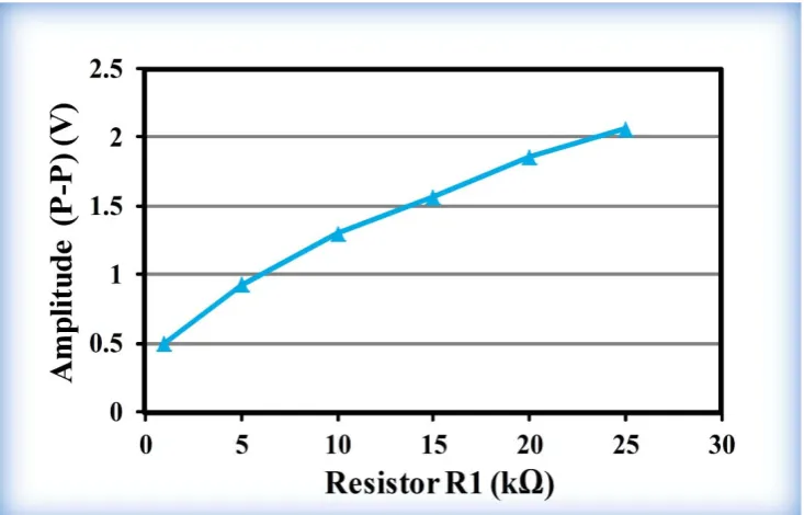
design……….. 90 Figure 3.6: Amplitude (P–P) variation with the bias current IB3 and resistor
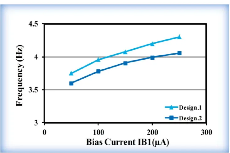
R1, (a) amplitude (P–P) variation with IB3 for the two ELF WFG designs, (b) amplitude (P–P) variation with R1 for the first design and (c) amplitude (P–P) variation with R1 for the second design……….. 93 Figure 3.7: Frequency tuning with bias current IB1 for the two ELF WFG
designs………. 94 Figure 3.8: Frequency tuning with resistor R2, (a) for the first ELF WFG
design, (b) for the second ELF WFG design……….. 95 Figure 3.9: The layout of on-chip identical units OPRPP and OPRRP
resistors, in series……… 97 Figure 3.10: Layout for MIM capacitor……….. 98 Figure 3.11: The layout for the two WFG circuit (design_1 and design_2).
The layout on top right corner and bottom right corner represent the complete layout for the two WFG circuit including the on-chip designed MIMCAP for MLF WFG with 40pF, and for ELE WFG with 1nF for design _1 for area comparison……….
100 Figure 3.12: A close view of the complete layout (excluding the capacitor) for
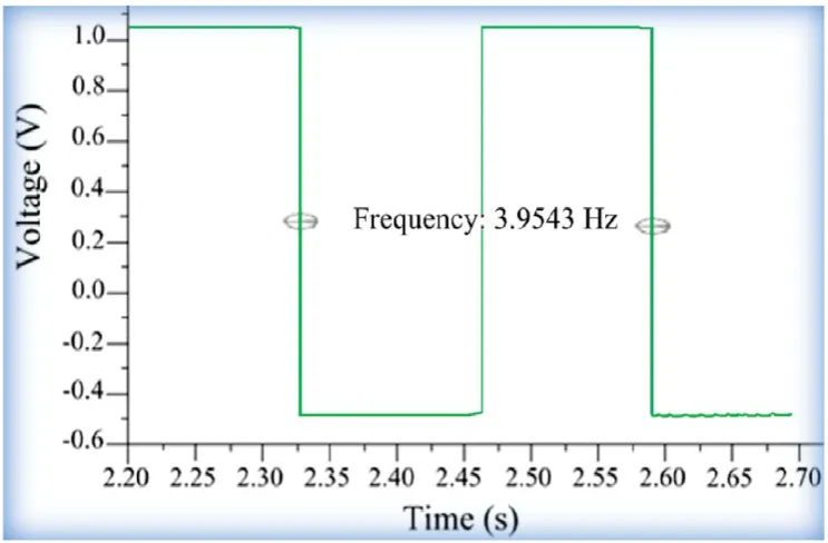
the two ELF WFG circuit, for chip fabrication (a) for the first design, (b) for the second design. The top is the Schmitt Trigger circuit, while the rectangular box is the combination of different types of on-chip resistors……… 101 Figure 3.13: Package of the two ELF WFG circuit in PGA……….. 102 Figure 3.14 Chip photo-micrograph illustrates the location of the integrated
two ELE WFG circuit.……… 102 Figure 3.15: Chip outputs of the CMOS ELE WFG for the first design………. 103 Figure 4.1: Block diagram of the proposed mixed-signal CMOS waveform
generator. Oscillation frequency of WFG core circuit is fWFG (band I) and the digitally channelized selectable output frequency
xviii
Figure 4.2: A schematic diagram of the core square/triangular WFGINT based
on gm-C integrator with clock and clock _bar generator………... 112 Figure 4.3: A single stage gm-C integrator based on CMOS OTA, (a) circuit
implementation, (b) integrator symbol and (c) building blocks
diagram………... 113
Figure 4.4: Schematic diagram of the WFGINT circuit operation, (a) transfer characteristic of the Schmitt trigger design, and (b) the square and triangular waveforms of the designed WFGINT circuit……… 117 Figure 4.5: The schematic diagram of the designed TGMS D-FF for a
divide-by/2 frequency division circuit……… 128 Figure 4.6: The implementation of the designed TGMS D-FF for a
divide-by/2 frequency division circuit………... 128 Figure 4.7: Multiplexers and path selector along with output driving circuit... 130 Figure 4.8: The complete architecture of the dual-band 16-channel
mixed-signal WFGING with ultra-wide low frequency tuning range…….. 131 Figure 4.9: Simulated transient square waveform output of the WFGINT 134 Figure 4.10: Spectrum analysis of the square waveform signal (fWFG = 17
kHz) in simulation profile………... 134 Figure 4.11: Simulated transient triangular waveform at the integrator output.. 135 Figure 4.12: WFGINT circuit analysis for the frequency stability with
temperature variations………. 137 Figure 4.13: Eye diagram simulation results for the designed WFGINT……….. 137 Figure 4.14: Simulated transient response of the clock and clock_bar
generator………. 139 Figure 4.15: The 16 channel output square waveforms digitally selectable
through MUX1, MUX2 and PS……….. 141 Figure 4.16: Power versus generalized width WN………... 143 Figure 4.17: Power dissipation versus supply voltage of the FD circuit………. 144 Figure 4.18: WFGING frequency versus supply voltage……….. 144 Figure 4.19: The simulated speed-power trade-off of the FD circuit………….. 145 Figure 4.20: The simulation result for power and frequency versus V_tune….. 145 Figure 4.21: The complete layout (including the capacitor) for the
xix
mixed-signal WFGINT circuit, (b) show close views of the WFGINT core circuit, (c) D-FF, (d) MUX1, and (e) PS circuit………..
149 Figure 4.22: Package of the analog WFGINT and the digital model circuit in
PGA………. 150 Figure 4.23: Chip photo-micrograph illustrates the location of the integrated
mixed-signal dual-band WFGINT circuit………... 150 Figure 4.24: Experimental measurement set up for the fabricated oscillator….. 151 Figure 4.25: Measured chip outputs, (a) square waveform of the core WFGINT,
(b) FFT spectrum analysis of the generated square waveform signal, (c) triangular waveform of the integrator, and (d) clock and clock_bar translation outputs………... 153 Figure 4.26: Amplitude (P–P) variation comparing measured results and
simulation, (a) with V_tune bias current IB3, and, (b) with R. 155 Figure 4.27: The measured profile values of the oscillation frequency vs.
V-tune of the WFGINT output signal, compared with the simulation profile values and the related results for 10 pF, 100 pF and 1000 pF load capacitor values respectively………. 157 Figure 4.28: Optimization flowchart of the designed CMOS dual-band
16-chanal mixed-signal waveform generator………... 160 Figure 5.1: Human skin layer……… 166 Figure 5.2: Current response of skin to the application of a square-wave
voltage pulse………... 167
Figure 5.3: Proposed adaptive biased CMOS active electrode circuit, (a) circuit implementation, with input stage bias current set dynamically by two mechanisms, first, by the simple current mirror and secondly, by applying adaptive biasing, and (b) equivalent circuit representing the voltage follower active electrode circuit……….. 170 Figure 5.4: Simulated transient response of individual active electrode buffer
xx
employing two identical active electrodes……….. 177 Figure 5.6: Simulated transient response of the dual active electrode circuit
driving a 50kΩ floating load in a differential fashion displaying a transmitted bi-phase square waveform with, (a) approximately ± 1V differential output voltage, and (b) ± 40μA differential output
current………. 178
Figure 5.7: The two identical active electrode circuits (a) layout, (b) package of the microchip and (c) Chip photo-micrograph of the fabricated
die……… 180
Figure 5.8: Experimental set-up for the active electrode chip output
waveform measurements.………... 181 Figure 5.9: Oscilloscope trace of the differential output waveform signal of
the dual identical active electrode circuits……….. 181 Figure 5.10: A proposed proto-type electro-bio-stimulation system using the
fabricated active electrode-pair complete with (a) mixed-signal CMOS waveform generator, WFGING (IC1 in chapter 4), (b) the active electrode-pair (IC2), and, (c) solar panel charged regulated power-supply. The complete encapsulated bio-medical device with electrode contacts is shown in (d)………... 184 Figure 6.1: Protein structure of co-receptor CCR5 and its sequence. The
image outlines the residues of N-terminus, and C-terminus, residues of the 7-TM region and of the extracellular (EL) and intracellular loop (IL) regions respectively………. 190 Figure 6.2: Nuclear pore complex structure……….. 195 Figure 6.3: A heterogeneous tripartite structure of FGNup153, comprises
three different domains, N-terminal domain, zinc finger domain,
and C-terminal domain………... 197 Figure 6.4: Nuclear pore complex model for protein import and export of
large macromolecular proteins that are recognized by nuclear transport receptors (NTRs) and passage them through the central channel……… 201 Figure 6.5: The electrical test glass chamber with stainless steel wire
electrodes………
xxi
Figure 6.6: Experimental set up for electrical stimulation test. Healthy human buffy coat samples were exposed for 2h to low frequency bipolar square waveform pulses of 5Hz, 10Hz and1000kHz with 1Vpp in a 30ml capacity glass chamber, 3cm in diameter, with stainless steel wire electrodes………. 207 Figure 6.7: Purifying and coating coverslips with HCl and poly-lysine
respectively, to assure cells adhesion……….. 208 Figure 6.8: Cells adhesion on coverslips. Buffy coat samples spread and
plated on coated coverslips that are mounted on Parafilm to prevent the coverslips from moving, and then incubated in oven for 30 min at 37 °C……….. 209 Figure 6.9: The steps of experimental procedure for immunofluorescence
cells staining……… 212
Figure 6.10: Experimental setup for acquiring images. (a) A Carl Zeiss Axio Star plus microscope with AxiosVison software, and (b) the tested and most successful sealed coverslips used in this experiment………... 213 Figure 6.11: Cell surface expression of CD4 (green) and CCR5 (yellow) in
human healthy buffy coat samples, for unstimulated (A) cells and for electrically stimulated cells (B) in response to low frequency electrical simulation conditions of 5Hz and 10Hz with 1V for 2h, analysed by immunofluorescence microscope. The intensity and distribution of the fluorescence on the cell membrane and cell surface represents the concentration of CD4 expression and CCR5 expression for unstimulated cells as shown in (b) and (f), and for electrically stimulated cells of 5Hz and 10Hz as shown in (c), (d), (g) and (h) respectively. (a) and (b) images display a wider view of the CD4 and CCR5 cell populations……… 215 Figure 6.12: Immunofluorescence assay for cellular distribution and binding
xxii
epitope in this region, in response to a low frequency electrical field. The images (a), (b) and (c) show a wider view of the cell population, the binding activity of unstimulated cells (A), CCR5 (yellow) in (d) with 3A9 (red) in (e) is shown in orange (merge) in (f), while (g) represents IgG as a control, (h) and (i) represents the CCR5 (yellow) in response to electrical stimulation (B) of 5Hz and 10Hz respectively………. 217 Figure 6.13: The immunofluorescence microscope images of the distribution
and pattern of the FGNup153. The images DAPI (blue) in (a) and (d) with Nup153 (red) in (b) and (e) is shown in purple (merge) in (c) and (f), displaying a wider view of the cell population for unstimulated cells (A) respectively. The co-localization of FGNup153 with mAb for (B) cells electrically stimulated with 5Hz and 10Hz incubated for 15min at -20°C in cold 100% methanol are displayed in (g), (h), (i) and (j), (k), and (l), respectively. For cells stimulated with 5Hz and 10Hz (green) that were fixed in 4% PFA and permeabilized by incubating for 5 min at room temperature with 0.5% Triton X-100 the data is not
xxiii
Lists of Tables
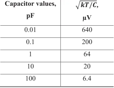
Table 2.1: A comparison between capacitor values and corresponding kT/C
noise……… 47
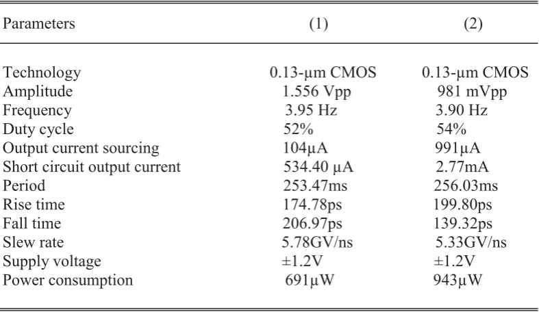
Table 3.1: Transistor dimensions for the two ELF WFG designs (1 and 2)… 89 Table 3.2: Component values for the two ELF WFG designs (1 and 2)…….. 89 Table 3.3: Comparison of the simulation performance of the first ELF WFG
design (design 1) with the second ELF WFG design (design 2)… 91 Table 4.1: The power and area versus generalized transistor width for the
designed FD circuit………. 143 Table 4.2: Simulation results of the outputs of the dual band WFGINT
designed circuit………... 146
Table 4.3: The tuning range of the oscillator frequency for the WFGINT core (band I) for C=10pF, with V-tune varied from ̶ 0.9V to +0.9V, and the equivalent oscillator frequency the circuit can provide, with 16 channel FD circuit (band II)………... 158 Table 4.4: Comparison of the proposed WFGINT with ELF WFG of this
work and with some other solutions in the reported literature…… 162 Table 5.1: Performance and comparison of the proposed active electrode
1
Chapter 1
Introduction
1.1 Biomedical Integrated Circuit
Design
2
engineering design for investigating the electro-active biological cell and developing smart electro-medical devices [3]. Since designing a suitable device for electro-medical treatment depends on the condition of the disorder or disease, understanding the biological system features and the disease conditions, from an electronic engineer's point of view, is therefore, essential and potentially beneficial to assist the designer in developing the required electro-medical treatment devices, using the application of an electric field for medical treatment. The application of an electric field for electrotherapy is considered one of the oldest medical treatments since Ancient Greece and the most important documented medical therapies recognized by scientists [4, 5]. It is potentially useful as drug-free relief and overcomes the deficiencies of several conventional medical treatments. It has potential for treating a variety of chronic diseases that have significant social and economic effects. It may assist when therapeutic drugs become useless and cannot be replaced, as in untreatable diseases like cancers and Human immunodeficiency virus that develop drug resistance.
3
fixed inside the eye as a retina implant to electrically stimulate the cells of the eye which is successfully bringing vision to blind people who have genetic retinal degeneration [9]. Programmable multichannel stimulators based on electrical stimulation of the auditory nerve in the cochlear region are used for cochlear implant prosthesis in deaf patients to recover hearing sensation [10]. Today, more than 130,000 deaf people in the world are using a cochlear implant which allows them to hear normally [3]. Design techniques to provide electrical signals are also used in the cardiac pacemaker system for cardiac activity to improve a patient’s heart’s rhythms. It has become a remarkably important treatment technique for a slow heart rate [11, 12]. The design of implantable biomedical devices that use the application of electrical stimulation is not limited to the brain, eye, ear, and heart areas. Implantable electrical stimulation devices have been also used for intravesical electrical stimulation (IVES) in diagnosis and treatment of lower urinary tract dysfunction, to enhance bladder sensation and to improve bladder contractility in patients with impaired bladder emptying [13]. Today, implantable electrical stimulation devices are used for vestibular implants to treat balance disorders, brain implants to treat speech disorders, and implants for treating urinary incontinence [3]. Moreover, in a new area of implants, electrical stimulation devices are being developed for the treatment of immune inflammatory disorders of the vagus nerve [14].
4
effect, has been used for breast cancer therapies when conventional treatments become useless or costly, with serious side effects, and for chemo-resistive patients. This technique specifically controls electric fields of short duration and high intensities, to open up transient pores (aqueous pathways) through semi-permeable membranes and tissues, allowing targeted delivery of therapeutic materials including drugs, antibodies, and genes [17]. Nanosecond pulsed electric field (nsPEF) technology is also used to treat skin cancer in humans. The effects of nsPEF therapy are highly localized to only the cells located between suction electrodes, while tissues outside the edge of the suction electrode show no effects from the therapy [18]. These types of biomedical devices based on electrical stimulation therapy, were approved by America’s Food and Drug Administration (FDA) as a standard method for medical treatments, which exist in the market.
The requirement for both types of device is to develop an appropriate biomedical electrical circuit solution for each particular electro-medical treatment device. In both types of smart devices however, it is necessary to generate and deliver an appropriate electrical signal with specific waveform and frequency, to be applied internally or externally to a particular area of the body. Waveform generators (WFG) and electrodes circuitry can communicate with the electro-active biomolecule, highly stimulating certain events arising in a complex biological system. The design of WFG, as well as electrodes, therefore, has become important in a wide range of biomedical signal processing systems. These devices must be portable, miniaturized, adaptable, safe, secure, reliable, operate with low power battery and low cost. Examples of the development of implantable and non-invasive biomedical devices that utilize waveform generators as discussed in this section are summarized in Figure 1.1. Such devices should be accurate, and take into account the interference between biological materials and the device elements. This can be assured by monitoring the biological activities and the responses, with application of an electrical field. These devices must operate at low voltage and be safe to use without exceeding the health safety standards of the International Commission on Non Ionizing Radiation Protection (ICNIRP) and the U.S. Federal Communication Commission (FCC) standards state that human exposure must be restricted to lower levels of electric field [19].
5
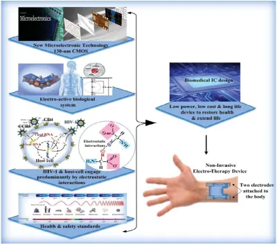
Figure 1.1. Schematic diagram representing the development of a variety of implantable and non-invasive biomedical devices in the real world. These devices use the application of an electric field with an appropriate electrical signal and specific frequency to be applied internally or externally to a particular area of the body, to treat a variety of disorders or disease conditions, and to improve patients’ lives [3][7][9].
6
host cell proteins, that is dominated by electrostatic interactions, considered the main driving forces for the progress of the disease state, represents a desirable objective for such an approach. Therefore, this research project will introduce the underlying mechanism of the disease and outline a path that will combine bio-electrochemistry science at the molecular level, engineering principles and medical science to advance functional design in vitro as a promising foundation and value for the establishment of HIV-1 treatment in vivo.
1.2 Relevance
Today, health care issues demand concern all around the world. It is an area that involves private and public sectors with significant social and economic impacts. Good health is essential for carrying out the basic daily life tasks through to the development of nations. The development of societies is evaluated according to the health of their people, because health is a balance between people and their environment. People with illness or chronic pain may struggle to participate and communicate with others in everyday life. This may occur in both chronic illness and unexpected disease which can be an enormous psychological burden and can cause serious handicaps, especially if the disease causes feebleness or death in human and in economically important animals. The impact of such disease is measured by financial cost, mortality and morbidity. Pathogenic disease is considered the greatest cause of death, and kills millions of people worldwide every year, more than all other diseases [20-23]. Most pathogenic diseases are infectious and caused by a micro-organism such as fungi, bacteria, and viruses, which affects the normal physiological functions by causing dysfunction or tissue damage. However, there are different types of pathogenic disease around the world which need significant consideration.
7
AIDS [21]. Thus it can be concluded that HIV-1 disease can be a significant economic burden including healthcare-associated infections (HAI) and costs involving hospital, nursing, laboratory and diagnostics, investigations, medical treatment, outbreaks of disease and infection prevention, time and loss of production. In United States, the cost burden for HAI is between about 25.0 and 31.5 billion dollars per year. In English hospitals, it was estimated at 1.6 billion dollars which is 1% of the total national hospital budget. The global goal is to prevent and treat disease, to reduce the disease burden. Many health organizations such as the World Health Organization (WHO) and Centre for Disease Control and Prevention (CDC) are organizing and monitoring many treatment programs and have developed a strategy for the 21st Century that improves the people’s health, to reduce the chronic disease death rates annually for the next 10 years, by 2%. The four major goals of the CDC are: a) surveillance and response, b) applied research, c) infrastructure and training, and d) prevention and control. Achieving these goals will assist in treating pathogenic disease, particularly HIV-1 now, and preventing it tomorrow [22, 23].
1.2.1 Virus Replication
8
involved in different stages of HIV-1 entry, and for replicative capacity. Thus co-receptor CCR5 plays a key role in the development of HIV-1 infections, and the lifecycle of the virus could be easily disturbed without CCR5 binding affinity [25]. After the fusion has occurred, the core of the virus, which includes the two RNA genomes and the important enzymes, is then released into the cytoplasm of the host cell. The HIV-1 life cycle is accomplished by import and export and passage of their large molecules infecting viral particles’ pre-integration complex (PIC) and the viral RNA respectively, through nuclear envelopes, utilizing host nuclear transport protein, nucleoporin Nups153, one of the nuclear pore complex (NPC) components [26, 27]. Thus HIV-1 cannot reproduce without the host cell proteins. It controls the activities of the host cells allowing its envelope domain protein to assemble with host cell domain proteins with a large conformation change, undergoing structural rearrangements to facilitate fusion and making new copies of itself inside the cells; this harms the immune system causing weakening and damage to the natural body defenses. HIV-1 host cells interaction is predominantly by charge-charge interactions (more details in Chapter 6) to control all their metabolic capacities [24, 28, 29], which play an important role in the HIV-1 life cycle replication. This creates many difficulties for producing the exact drugs to fight against the viral cycle without harming the human hosts, therefore, HIV-1 disease have no cure until now. It has the capability to develop drug resistance to therapeutic agents through multiple mechanisms. It is a mutation associated with responses to the therapeutic drug [30]. In one patient, the virus can change into a quasi-species to escape the host immune system which increases the pathogenicity of the virus and presents a challenge for vaccine development. The complex regulation of the replication and reformation to penetrate host cell defense mechanisms can also escape antiviral treatment [21].
9
approaches, however, is by using a cocktail of anti-HIV-1 drugs at high dosage to prevent the development of drug resistance. This type of treatment deactivates their genomes to prevent replication, but does not destroy the provirus HIV-1 DNA in the nucleus of the host cell [34].
For prevention and treatment of diseases caused by retroviruses using a traditional approach, frequent recombination and high mutation rate in the virus creates multiple problems. Thus, such diseases require series routines for monitoring therapeutic agent efficiency and response to resistance. These need high quality techniques that are used for diagnostics and testing of resistance genotyping of such diseases. This is costly and might not be available in all medical laboratories [20]. It is high risk due to the side effects of therapeutic drugs and sensitivity to the new modification of the therapeutic agents. An example of the side effects such as anemia, depression, difficulty sleeping, headache, dizziness, rash, fever, nausea, stomach pain, diarrhea, vomiting, loss of appetite, constipation, darkening of palms, hair loss, tingling, numbness, or burning sensation, muscle aches, hypersensitivity reaction, liver and kidney problems, high blood sugar and cholesterol, and fatigue [35]. The new approach is to select specific therapeutic drugs based on genetic testing, now considered in modern clinical practice because of a significant number of deaths, (about 100,000 annually and about 2 million annual hospitalizations in the United States), related to inappropriate drug reactions, which is a serious problem in industrialized countries [20]. It is a big challenge, involving complex pharmaceutical process and experimental laboratory cost. These problems still remain in the recent fight against the most devastating pathogen in human history.
10
1.3 Develop Concept
Proteins are built up from amino acids (AA) that are composed of a central carbon atom bonded to a hydrogen atom, an amino group (N-terminal), a carboxyl group (C-terminal) and a side chain (R) with covalent bond as shown in Figure 1.2. The presence of ionized amino and the carboxyl (COO-) group produces a predominant dipolar which can be then rotated. Although, typically there are 20 amino acids in nature, their distinctive structures are due to the presence of various non-polar and polar amino as well as charged acid side chains. The specific protein sequence formed by its amino acids are connected together to form polypeptide polymer chains and build up the primary structure of a protein. Accordingly, each polypeptide also has various non-polar and polar amino acid side chains and produces dipolar. Although the peptide bond is polar, it cannot rotate freely, thus, its motion is restricted [21]. However, these polypeptides are folded into a three-dimensional (3D) structure by a variety of intramolecular interactions, such as electrostatic force within the side chain sequence which characterizes the active proteins that affect the final protein conformation [1]. Commonly, in the 3D complex structure of the protein, however, the non-polar side chains (hydrophobic residues) are stifled inside the protein core, while the polar and charged groups are distributed on the protein surface and considered as the predominant group to be in contact with other predominantly protein groups, and with the aqueous medium interact in a complex process to perform various cell functions. The structural rearrangement of the protein changes its molecular shape, due to the bond rotation, without breaking the covalent bonds defines the protein conformation [34].
11
12
The HIV-1 and host cell interaction process is characteristically dominated by charge–charge interactions to induce conformational changes, in order to control host cell protein functions, and to stimulate different signals that are vital for virus cellular processes and replication. Since HIV-1 viral attachment and fusion requires stable and sustained intractions with the target cell, the intraction of the HIV-1 envelope proteins domain region with the coreseptor domain region, is considerably diminished, and hence, the dynamic forces of a virological synapse (to-cell interaction to allow cell-to-cell transmission) [39] are possibly inadequate to maintain the attachment of the HIV-1 virus for a sufficient period of time. Such stable interactions can be only provided by the immunological synapse (signaling proteins for cell activation) [40]. Similarly, the applications of the electrical stimulation could disturb the binding process of its effective factors that mediate the passage of its large macromolecular infected particles and its RNA through NPC. Thus the HIV-1 virus cannot conjugate with the target cells, disturbing its life cycle, and suggests that the mechanisms of the inactivation signal induces virus death. This may disturb the life cycle of the HIV-1 virus and hence, its replication, with no potential risks and harm to the host cells compared to the pharmacological approach.
13
The movement of the charged molecule and the free ions, in response to an applied external electrical field can also be a useful mechanism to induce an action comparable to the normal cell endogenous electrical field. An endogenous field, which induces variation in membrane potential, due to the movement of the charged residues in the intrinsic plasma membrane proteins, as well as free ions, has importance in biological processes, such as wound healing and tissue regeneration. Since the surface charge can change with the pathophysiological state of the cell [36], thus inducing a small electric current can also enhance the normal cell functions by inducing a variation in membrane potential, and affect subcellular mechanisms, particularly the intracellular Ca2+ concentration or other voltage-dependent ionic activities [46]. An additional notable feature of this electrical stimulation is its cellular specificity. Therefore, the parameters of the generated electrical pulse can be designed and selected in order to stimulate only one particular type of tissue, such as blood, nerve, muscles, urine, leaving the others unaffected [47]. Moreover, in the electrical stimulation approach, the type of waveform must be carefully considered. Using a periodical waveform with certain stimulation frequencies can interact with the periodical intrinsic oscillators of the biological cell networks, which enhances their intrinsic oscillatory activity [48], a phenomenon that describes the natural frequency of the human body, which is an essential process in the living organism that enhances cell communication [49]. Since disease can disrupt the biochemical systems in biological cells, this inhibits the normal protein synthesis in lymphocytes, therefore, applying certain stimulation frequencies can enhance the biochemical parameters of the blood and normalize protein synthesis in lymphocytes [50].
14
Theoretically, and in my opinion, the periodical low frequency square waveform with wide pulses can block the interaction between the virus and the domain regions of the host cells for a sufficient period of time, therefore, the HIV-1 virus cannot mutate and develop resistance in the absence of the host cell proteins as in traditional pharmaceutical approaches, so that the HIV-1 virus will then vanish. Interestingly, using an application of periodical low frequency bipolar square waveform signal and low voltage electrical field can, therefore, induce enhancement and/or inhibition effect, prompting an antiviral state for a period of time, but is not expected to seriously disturb the host cell protein structure and its conformation state. Indeed, the protein molecules have non-polar hydrophobic amino acid residues building up the core, and the polar and charged amino acid residues are mostly located on the surface of the molecule, and there is no rotation around the peptide bond, thus the back bone of the protein does not rotate freely and only the polar or charged site chains rotate [1, 21]. These electrically induced protein transformations can be studied invivo/in-vitro as blood-cell treatment and as anti-HIV-1 electro-therapy. This may offer an antiviral therapy to target the most devastating pathogen in human history (more details in chapter 6).
Figure 1.3 (a) and (b) summarizes and shows the development and design steps of the biomedical intgrated circuit for electro- therapy device of this research project.
15
[image:39.595.126.527.84.438.2](b) Schematic diagram shows that advances in 1) microelectronics technology involving new CMOS biomedical IC design, 2) bio-electro-chemistry science including cellular function, electro-active biological cells and their responses, and 3) knowledge of the disease condition, concerning the underlying mechanisms of the biological cells and disease state (HIV-1 and host cell engage predominantly by protein charge-charge interaction), are combined in this research project, in order to develop the concept and design a biomedical device capable of communicating with electro-active biological cells and how this could be utilized for biomedical treatment applications.
16
1.4 Research
Goals
The goal of this research project is to combine advances in engineering (involving new CMOS technology) and biology (including the electro-active body medium) as well as the underlying mechanisms of the biological cells and disease state (HIV-1 and host cell engage predominantly by electrostatic interactions) to develop the concept and introduce a biomedical device capable of communicating with body tissue and cells, for biomedical treatment benefits. A corresponding goal is the characterization of this concept in-vitro, and, if possible, the device in-vivo, to investigate the effect of low frequency and low voltage electrical pulse on human blood cellular proteins, to stimulate a potential reaction that can induce a short-term, or long-term anti-HIV-1viral state. Besides, this research project can develop knowledge for advanced technological electro-medical treatment devices, their design, structure and applications. The research project therefore, has the following aspects:
1. Concept development for anti-HIV-1 electro-therapy.
2. Biomedical IC Design. A novel low power and low frequency non-invasive biomedical device comprising a dual-band WFG with ultra-wide low-frequency tuning range and an active-electrode-pair will be developed, based on a new 130nm IBM CMOS technology.
3. Bio-electrochemistry experimental work. A theoretical analysis, experiment design and performance will carried out in in-vitro environments to examine the influences of the periodical low frequency bipolar square waveform signal and low voltage electrical field on human blood cells.
1.5 Scope of This Study
17
generated from an electrical WFG. In this work, non-invasive techniques which do not require implantation into the body, will be the focus; a device which can generate, control and deliver an appropriate low frequency low voltage pulse via electrode, through the low-resistance skin surface to a patient’s blood. This method has practical advantages, as it is convenient for the patient, with no harm. The biomedical device of this research project comprises a mixed-signal low power dual-band WFG chip with a wide low frequency tuning range. The circuit provides periodical square/triangular waveforms along with a square waveform complementary signal for low frequency electrical stimulation applications. Two WFG approaches will be developed in this research project, for comparison. Since the aim of this work is to transfer electrical signals, in a specifically controlled fashion, through the electro-active tissue, an active electrode will be developed to provide biphasic square waveform output signals to overcome the deficiencies of using passive electrodes. Thus, a good quality signal can be transmitted by reducing the sensitivity to cable and environmental noise. The WFG with surface electrodes is battery operated with low power consumption, and hence, low cost. In the light of this an in vitro bio-electrochemistry experiment will be carried out to examine the concept of this research project. The following objectives clarify the works carried out in this research project:
1. Develop a new theoretical model and derivative of a novel mathematical model to determine the controllable variable parameters as well as component sizing for high gain, low frequency, low power, and small chip area WFG circuit design and also to study the trade-off between these important parameters.
2. Develop IC for the extra low frequency (ELF) WFG design comprising a novel hysteresis Schmitt Trigger and utilizing a RC relaxation timing network.
3. Develop a novel concept employing a combination of the different types available of on-chip p+ polysilicon resistors in the 130-nm IBM CMOS process, in order to fully implement the large integrated resistors.
4. Develop small-size on-chip capacitors with low capacitance.
5. Develop IC for a novel power dual-band WFGINT design with ultra-wide low-frequency tuning-range comprising a hysteresis Schmitt Trigger and realizing an integrator relaxation timing network along with a novel two band tuning system. 6. Develop IC and derive a novel mathematical model integrator building block
18
tasks; (1) the timing network, (2) for low frequency design, and (3) for the electronically tuneable WFGINT circuit (band I), linearly controlled by the bias current (IB) of the gm-C integrator through a smart and simple tuning technique. 7. Develop a novel low power hybrid frequency tuning technique composed of two
models; (1) the analog (band I, electronically adjusting the bias current of the gm-C integrator), and (2) the digital model (band II, frequency divider), comprised of a 16 stage divide-by-2 frequency divider (FD) in series with dual 8-1 multiplexers (MUXs) and a path-selector (PS). The PS output can drive complementary active electrode circuits to realize a biphasic square waveform for electro-medical stimulation using the chosen frequency.
8. Develop and optimize a low power miniaturized IC for a novel active electrode-pair design to deliver an appropriate biphasic and monophasic waveforms for low frequency simultaneous multichannel biomedical applications.
9. Implement and simulate the electronic model in VLSI.
10. Set-up experimental measurement to validate the fabricated chip performance. 11. Evaluate the design using a comparison of the proposed circuit design and the
signal characteristics with recent and relevant publications and literature.
12. Develop the theoretical model of the complete free energy non-invasive biomedical device of this research project involving signal-processing circuitry, by mounting all IC signal source and the active electrode on the electrodes (transducers) with solar panel charged regulated power-supply.
13. Develop applications. Complete the theoretical analysis of the underlying mechanism of the HIV-1 virus and host cell interaction, in order to design and set up the bio-electrochemistry experiment in-vitro, to study the effect of the generated periodical low frequency bi-phase square waveform signal on the cell surface receptor CD4 protein, co-receptors CCR5 protein and on the binding activities of CCR5 N-terminal domain, as well as on the distribution of nucleoporins Nup153 utilizing the Immunofluorescence microscopy technique. Compare the results with recent and relevant publications.
19
circuit design of this research project is state-of-the-art in terms of safety, low power, miniaturization, light-weight, and portability; an IC solution that can be suitable for use with electrical stimulation applications. In particular, the proposed WFG design is important for battery-operated implantable and non-invasive biomedical devices, enabling the reduction of the overall system cost.
The bio-electrochemistry experiment is developed to examine the concept of this research project, and to study the effect of the designed electrical signal on the molecular mechanics of HIV-1 and host-cell interactions. Since this type of experiment is considered as including high level physical contaminants (PC3) which is not appropriate in Massey University labs or any other normal labs, the electrical stimulation test is performed on healthy human blood cells only. Therefore, the in in-vitro biological experiments required for this project work were conducted primarily in Human Nutrition lab building 27, and the biology lab building 10, School of Food and Nutrition (SoFN) laboratories, which are permanently located at Albany campus, College of Health, Massey University. Health and safety induction for laboratory users and for the campus environment as well as the biological compliance for physical containment (PC1 and PC2) was completed, before beginning any work.
20
1.6 Thesis Overview
Chapter 1 provides a brief introduction to the need for design of biomedical integrated circuit solutions for bio-electrical stimulation to restore health, specifically, WFG and active electrode design for biomedical devices. This chapter briefly describes the relevant disease and a novel an appropriate electro-medical concept for this research including the importance of the protein structure involved in HIV-1-host cells interactions, predominantly by charge-charge interactions, which play an important role in its life cycle replication. Based on this, a novel biomedical IC solution for a non-invasive biomedical device is proposed to investigate the applications of a periodical low frequency bi-phase square waveform pulse on the human immune response, specifically, the molecular mechanism of HIV-1 and host-cell interactions.
Chapter 2 provides an overview of this project’s system model, theory, design, and approaches. The chapter starts, with a brief summary of the important properties of the WFG followed by a basic theory of oscillators and oscillator approaches. Relaxation oscillator architecture and the hysteresis Schmitt Trigger concept are explored along with the principles of operation of a WFG circuit. Two specific WFG circuit theories related to this research project are introduced. WFG approaches that have been developed by various researchers are presented. This includes a comprehensive review of a recent CMOS WFGs design approach based on hysteresis Schmitt Trigger, termed “current mode operational trans-conductance amplifier (OTA)” which has shown massive potential for low power circuit design. The importance of the relaxation timing network, including passive RC and active integrator gm-C approaches, are also discussed. Tuning system approaches including analog and digital models are provided in this chapter. A comparative study of a number of different flip-flops (FF) architectures was reviewed, to classify those that are the best power and area efficient designs to re-design and use for a FD designed circuit. Sources of power dissipation in a digital model are discussed. Finally, a brief summary of the active electrode feature and approaches is provided. This knowledge is essential to complete the system design on a single chip, using both the analog and digital circuit solutions.
21
by the characteristics of the OTA design, their design parameters are discussed at the start of this chapter, which is fairly important. The importance of the key factors for low power, low frequency and small chip area WFG circuit design is presented next, followed by circuit design and topology. Circuit operation and the mathematical derivations related to gain, frequency, duty cycle and its controllable variable parameters, with simulation and performance analyses, are described and presented in this chapter. Advanced physical design that defines the physical size of the circuit is introduced. Accordingly, a novel concept of employing a combination of the different types available of on-chip p+ polysilicon resistors in the 130-nm IBM CMOS process, used to fully implement the large integrated resistors, is also presented. Using the same topology, two sets of device dimensions and circuit components, designed and fabricated for comparing relative performance, silicon area and power dissipation, are also introduced. Experimental results and a comparison of the two fabricated ELF WFG designs with the circuits’ simulation outputs are presented in this chapter.
Chapter 4 presents design criteria, implementation and fabrication of dual-band CMOS WFG with wide low-frequency tuning range. Appropriate design requirements for a novel WFGINT circuit to increase the performance of the device are presented, followed by circuit design and topology including gm-C integrator realization. Circuit operation and the new mathematical derivations related to gain, frequency, and its controllable variable parameters, as well as component sizing for low power and low frequency WFG design, are discussed. A novel hybrid frequency tuning technique composed of two models, the analog (electronically adjusting the bias current of the gm-C integrator) and the digital (frequency divider) model, including a new mathematical approach, is also presented. The robustness of the designed WFGINT circuit, including temperature variation and signal integrity, is also presented. In order to optimize the layout for size, the technique to implement the device in analog and digital models is also described. The measurement results and comparisons of the fabricated WFGINT circuit design with 1) the circuit’s simulation output, 2) with the ELF WFG of this work, and 3) with reported designs, are also presented. The optimization flowchart of the designed dual-band WFGINT including the circuit design process performed in this work, is introduced at the end of this chapter.
22
stimulation. A brief introduction to the skin layer and skin electrical model study by different researchers is introduced, followed by the active electrode circuit realization of this work and the parameters that control the circuit performance. The circuit design, with theoretical analysis to optimize the performance of the active electrode circuit, is presented. Using the same topology, two identical active electrode circuits, developed and fabricated to drive the load in a differential fashion, utilizing a complementary active electrode circuit, are introduced. The measurement results and a comparison of the performances of the fabricated electrode chip with reported designs, are also presented. The new theoretical model, including a schematic diagram of the completed, proposed, non-invasive biomedical device, comprising a dual-band WFG, two identical active electrodes, power supply circuitry with free energy solar rechargeable battery, and biological interfacing device are also illustrated in this chapter.
Chapter 6 presents the in vitro Biological experiment design and performance to investigate the effect of low frequency electrical pulses on the human blood cells. A brief introduction to HIV-1 and host cell interaction and immune-based therapies in the pharmacological approach, followed by a brief analysis of the CCR5 protein structure as well as the NPC features and its important component, Nup153, is given at the beginning of this chapter. Details on protein-protein interactions that involve charge-charge interactions determining the interaction between the predominant HIV-1 regions and the predominant regions of host cell CCR5 and Nup153 reported by different researchers are described in this chapter which is important to support the concept of this research project. The concept of frequency–dependent polarization is also presented. A theoretical analysis with design and setup of the bio-electrochemistry experiment in-vitro, to examine the cell surface receptor CD4, co-receptors CCR5 and the CCR5 N-terminal domain as well as the distribution of Nup153 in response to electrical stimulation utilizing the immunofluorescence microscopy technique, is described and discussed in this chapter. Experimental results and valuable findings are illustrated and discussed in this chapter.