Xu, L. and Yao, L. and Sasse, C. (2006) Power electronics options for
large wind farm integration : VSC-based HVDC transmission. In: Power
Systems Conference and Exposition, 2006-10-29 - 2006-11-01, Atlanta. ,
http://dx.doi.org/10.1109/PSCE.2006.296412
This version is available at
https://strathprints.strath.ac.uk/37578/
Strathprints is designed to allow users to access the research output of the University of Strathclyde. Unless otherwise explicitly stated on the manuscript, Copyright © and Moral Rights for the papers on this site are retained by the individual authors and/or other copyright owners. Please check the manuscript for details of any other licences that may have been applied. You may not engage in further distribution of the material for any profitmaking activities or any commercial gain. You may freely distribute both the url (https://strathprints.strath.ac.uk/) and the content of this paper for research or private study, educational, or not-for-profit purposes without prior permission or charge.
Any correspondence concerning this service should be sent to the Strathprints administrator: [email protected]
The Strathprints institutional repository (https://strathprints.strath.ac.uk) is a digital archive of University of Strathclyde research outputs. It has been developed to disseminate open access research outputs, expose data about those outputs, and enable the
Abstract-- This paper describes the use of Voltage Source Converter based HVDC transmission (VSC Transmission) system for grid integration of large wind farms over long distance. The wind farms can be based on either Doubly-Fed Induction Generator (DFIG) or Fixed Speed Induction Generator (FSIG). The paper describes the operation principles and control strategies of the proposed system. Automatic power balancing during network AC fault is achieved without communication between the two converters. PSCAD/EMTDC simulations are presented to demonstrate the robust performance and to validate the proposed system during various operating conditions such as variations of generation and AC fault conditions. The proposed VSC Transmission system has technical and economic advantages over a conventional AC connection for integrating large wind farms over long distance.
Index Terms-- Converter, Doubly Fed Induction Generator, Fixed Speed Induction Generator, VSC Transmission, Wind farm.
I. INTRODUCTION
any large wind farms have been planned around the world. Due to environmental concerns and to maximize the energy generation, it is proposed that these wind farms are located some distance from the point of connection. For transmitting this bulk power over distances of tens or hundreds of kilometers, the developers and the system operators are facing a number of technical, economical, and environmental challenges. In general, two alternative connection methods are available, i.e., AC or DC. While they have their respective merits and shortcomings, they should be considered during the feasibility stage of the project.
Wind turbines using Fixed Speed Induction Generator (FSIG) provide a simple, rigid, and cost effective solution. However, a wind farm implemented using FSIG based wind turbine has difficulties to meet the emerging Grid Code in terms of the reactive power and voltage control requirements [1]. While many large wind farms under development will employ wind turbines based on the Doubly-Fed Induction Generator (DFIG) which offers several advantages including speed control, reduced flicker, and four-quadrant active and reactive power capabilities when compared to FSIG [2-3].
L Xu is with the School of Electronics, Electrical Engineering & Computer Science, Queen’s University of Belfast, UK. (email:
L Yao and C Sasse are with AREVA T&D Technology Centre, St. Leonard Avenue, Stafford, ST17 4LX, UK. (email: [email protected],[email protected])
However, even with the DFIG there are still problems for complying to the grid code if AC connecting is used. In particular, reactive power and voltage control requirements and ‘fault ride through’ during a solid AC system fault, etc, may not be met if without having significant modifications implemented to the design of the DFIG [4-5].
Although the connection of wind farms via AC technology has some advantages such as low cost, relatively simple layout, and the proved technology, etc, there are some disadvantages for a large wind farm with a long power transmission distance to the grid connection point via AC technology.
x With the increase in power transmission distance, long AC cables will produce large amounts of capacitive reactive power. It will reduce the cable transmission capacity accordingly. The capacitive power of the cable needs to be balanced by inductive reactive power in order not to create problems with high voltage and cable de-rating, therefore, large reactive power compensation is required;
x AC connection will result in the synchronous operation between the wind farm and the grid. Faults occurring on the grid will directly affect the wind farm and vice versa;
x Connection of wind farms via AC technology does not mitigate voltage and power variation effects due to the wind farms. Individual control of the voltage, power and reactive power of each wind turbine, combined with an overall energy management system to coordinate them, are essential.
The use of modern power electronics technology, namely FACTS and HVDC, provide solutions to these problems. AC connection with a Static Var Compensator (SVC) or a Static Synchronous Compensator (STATCOM) installed at the point of common coupling or HVDC connection based on either Voltage Source Converter (VSC Transmission) or conventional line commutated converter provide grid complied wind farm integration methods. Compared to AC connection, HVDC transmission offers many advantages for integrating large wind farms over long distance such as [6]:
x Power flow is fully defined and controlled;
x Transmission distance using DC is not affected by cable charging currents;
x Less number of cables required and low cable power losses.
Compared to conventional line commutated HVDC system, the principle characteristics of VSC Transmission are:
Power Electronics Options for Large Wind Farm
Integration: VSC-Based HVDC Transmission
Lie Xu, member, IEEE, Liangzhong Yao, and Christian Sasse
x It needs no external voltage source for commutation;
x It can independently control the reactive power flow at each AC network;
x Reactive power control is independent of active power control.
These features make VSC Transmission attractive for connection of weak AC systems, island networks and renewable sources to a main grid. However, VSC Transmission does have high power loss and high cost compared to conventional HVDC system [7].
In [8-9], an 8MVA VSC Transmission system was used to connect a 6MW wind farm to the grid. However, little information was given regarding the detailed system design and configuration. Multi-terminal VSC Transmission systems were proposed in [10] for transmitting offshore wind power to the grid. However, the system operations considered are mainly under normal condition and little attention was given during network disturbance which is one of the main requirements of the grid code [1]. Furthermore, the wind generators considered are either induction generators [8-9] or synchronous generators [10]. However, many wind farms under development will use DFIG and its operation and response to network disturbance are significantly different to other types of generators.
The objective of this paper is to provide a systematic study on the use of VSC Transmission as one of the power electronics options for integrating large wind farms based on either DFIG or FSIG. The paper is organized as follows. Section II outlines the proposed system and Section III describes the main control strategies regarding the VSC converters and the coordination of the converter control and the wind turbines during various operation conditions including AC fault. Simulation results are presented in Section IV and finally Section V draws the conclusions.
II. OUTLINE OF THE PROPOSEDSYSTEM
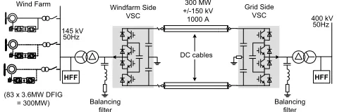
The single-line diagram of using VSC Transmission system for connecting a 300MW wind farm to the grid is shown in Fig. 1, where the wind farm can be based on either DFIG or FSIG. As shown, the VSC Transmission system proposed is based on 3-level Flying Capacitor (FC) converter which results in relatively low power loss compared to systems use 2-level or 3-level diode clamped multilevel converter [7]. One important aspect for FC converters is that the flying capacitor voltages must be balanced otherwise the stress on the power devices could increase and low order harmonics could be generated in the output voltage. Many different approaches using either extra hardware [11] or software control [12] have been developed. For simplicity, hardware based approach which uses a balancing filter of the R-L-C type [11] tuned at the switching frequency and connected at the output terminal of the converter is used in this study.
Depending on the type of generators used in the wind farm the reactive power requirement of the AC system on the wind farm side is different. The DFIG is capable of providing independent reactive power control and has a typical operating
power factor range of +0.95/-0.95. However, for the FSIG, the generator itself absorbs reactive power and the amount it absorbs varies with its speed/power. Normally, the reactive power compensation is provided via a thyristor (or mechanical) switched capacitor on turbine basis and it only guarantees to a certain limits.
300 MW +/-150 kV
1000 A 400 kV 50Hz Wind Farm
(83 x 3.6MW DFIG = 300MW)
145 kV 50Hz
Grid Side VSC Windfarm Side
VSC
HFF HFF
DC cables
Balancing filter
[image:3.612.310.549.153.233.2]Balancing filter
Fig. 1 Single-line diagram of wind farm integration using VSC Transmission (generator shown as DFIG but can be replaced by FSIG)
The VSC Transmission system transmits active power from the wind farm to the main grid via the DC cables. It also provides AC voltage/frequency control to the wind farm network and reactive power/AC voltage control to the grid network if required. A high pass filter (HFF) is connected at each side to absorb the high frequency harmonics generated by the converters during operation.
III. SYSTEMCONTROL AND OPERATION
For the normal operation of VSC Transmission system, one VSC is required to control its DC voltage to the set point. Furthermore, by maintaining a constant DC voltage, active power exchange on the two sides is automatically balanced. While for the wind farm AC network, the voltage and the frequency of the network need to be controlled. Automatic power balance between the two ends must be maintained at any conditions including AC fault.
A. Grid Side VSC (GSVSC)
The GSVSC is operated as the DC voltage controller and its control and operation are similar to those of a VSC Transmission system connecting two conventional AC networks [13]. The control system is usually defined in the synchronous d-q reference frame fixed to the network voltage. Outer DC voltage and AC voltage/reactive power control loops generate the reference d- and q-axis current orders respectively. Two inner current controllers are then used to control the converter d- and q-axis currents. As it is well defined, no more description is given here.
B. Windfarm side VSC (WFVSC)
The primary objective of the WFVSC is to maintain the local AC system to the set voltage amplitude and frequency. As no synchronous generator is assumed on the wind farm network, the operation of the WFVSC could be significantly different to those for connecting conventional AC networks. The principle of the control strategy adopted here is to control the WFVSC such that it behaves like an infinite voltage source. Thus similar to wind farms connecting to an infinite AC system active power generated by the wind farm is
automatically absorbed by the WFVSC and then transmitted to the grid via the GSVSC. Furthermore, the AC voltage and frequency of such infinite system will not be affected by the variations of the wind generator operation. Such system design significantly simplifies the control system and removes any possible interactions which may exist if extra loops such as frequency and/or active power control loops are used.
Z Sf Sa=M*sin(Zt+T) Sb=M*sin(Zt+TS) Sc=M*sin(Zt+TS)
Phase shifted PWM f M T PI Vac_ref Vac fref
T const
To converter
Sa
Sb
[image:4.612.313.555.103.243.2]Sc
Fig. 2 Control of WFVSC with FSIG or DFIG
The schematic diagram of the proposed control strategy for the WFVSC is shown in Fig. 2 for wind farm based on either FSIG or DFIG. As shown, the WFVSC is controlled and operated as an infinite voltage source with constant AC frequency and phase angle. The only control loop used is the AC voltage loop which controls the amplitude of the WFVSC output voltage via the modulation index M.
C. Automatic power balance during grid side AC fault
It is important that the active power is balanced even during AC fault conditions otherwise the system would have to be tripped and its normal operation be interrupted. During an AC fault on the grid network, the active power exchange between the GSVSC and the grid may be significantly reduced due to the reduced AC voltage. On the other hand, the WFVSC may still try to deliver the same amount power due to the lack of fast communications between the two stations. Consequently, the DC voltage may out of control. This is very similar to the situation during AC fault on one side of the converter which controls the DC voltage for a VSC Transmission system connecting two conventional Ac networks [14]. Therefore, it is important that the active power generated by the wind farm is automatically reduces such that the DC voltage can be maintained and system tripping can be avoided. Due to the significant differences of system operation between the FSIG and DFIG, different strategies are employed here to achieve power balancing during grid AC fault.
1) Wind farm based on FSIG
For FSIG, its output power can be regulated by varying its rotor slip via the change of network frequency. Thus, for wind farm based on FSIG, the output power from the wind farm is reduced by increase the AC frequency on the wind farm network during fault.
Under normal operation, the mean value of DC voltage is well controlled and the variation range is limited (say ±5%). When there is a fault on the AC side of the GSVSC, the DC voltage could exceed this band and therefore, abnormal DC voltage can be used as an indication of fault condition on the GSVSC side. The strategy employed here is to switch the WFVSC to DC voltage control upon detection of abnormal
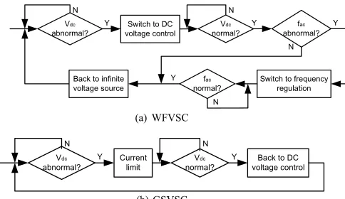
DC voltage. The flowcharts shown in Fig. 3 illustrate this approach.
Y Y
N N
Switch to DC voltage control
fac
abnormal?
Switch to frequency regulation fac normal? N Y Y Back to infinite
voltage source Vdc abnormal? Vdc normal? N
(a) WFVSC
Vdc abnormal? Current limit Vdc normal?
Back to DC voltage control
Y Y
N N
[image:4.612.61.294.160.219.2](b) GSVSC
Fig. 3 Flowchart of automatic power balancing during AC fault (FSIG)
As shown in Fig. 3, the DC voltage is constantly monitored by both converters and upon the detection of abnormal DC voltage (say +10% of nominal value), the WFVSC automatically switches to DC voltage control. In this mode the DC voltage reference is set slightly above nominal value (say +3%). Whilst for the GSVSC, it goes into current limit operation when abnormal DC voltage is detected as shown in Fig. 3(b). This prevents both converters from operating in DC voltage control mode at the same time to eliminate any undesirable interactions this could cause. DC voltage control of WFVSC is achieved via the control of phase shift between the WFVSC output and wind farm terminal voltage which indeed causes the AC frequency to increase. The turbine speed is increased during fault as its electric power output is reduced.
Once the AC fault on the grid side is cleared and the AC voltage recovered, the power exchange between the grid AC system and the GSVSC that is now still in current limit operation increases rapidly. Consequently, the DC voltage that was previously controlled at 1.03pu drops quickly after the clearance of fault due to the rapid increase of exported power by the GSVSC. This DC voltage is again detected by the control systems and then the converter modes are switched again as shown in Fig. 3. For the GSVSC, it backs to DC voltage control. While for the WFVSC, as the post-fault AC frequency and DFIG speed are much higher than their nominal values, directly switching the WFVSC back to infinite voltage source mode could result in large rotor slip for the FSIG and consequently, results in excessive power export by the FSIG or even cause system instability. Therefore, the WFVSC is temporary switched to frequency regulation mode to gradually reduce the AC frequency and the turbine speed to their nominal values by increasing the generated and transmitted power. Once the AC frequency backed to its rated value, the WFVSC is switched back to its pre-fault mode, i.e., infinite voltage source mode.
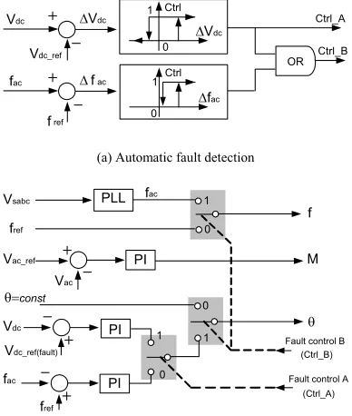
AC frequency, are used to select the control modes. A Phase Locked Loop (PLL) is used to measure the network frequency
fac and used as the output frequency of the WFVSC during fault period. During a fault, the DC voltage control loop is switched on first as both Ctrl_A and Ctrl_B equal 1. After the fault is cleared and the DC voltage backed to its nominal value, Ctrl_A becomes 0 but Ctrl_B stays at 1 due to the high AC frequency. Thus the frequency regulation is on. Once the AC frequency on the wind farm side backs to its rated value
Ctrl_B becomes 0 and the system is fully switched back to its pre-fault mode of infinite voltage source.
Vdc_ref
Vdc 'Vdc
'Vdc
Ctrl
1
0
fac 'fac
'fac
Ctrl 1 0 Ctrl_A Ctrl_B OR fref
(a) Automatic fault detection
f M T PI PLL PI Vdc 1 1 0 0
Fault control B (Ctrl_B) fac
PI 0 Fault control A (Ctrl_A) 1 Vsabc fac Vdc_ref(fault) fref
T const
Vac
Vac_ref
fref
[image:5.612.318.546.70.191.2](b) Block diagram of system control Fig. 4 Automatic power balancing during grid side AC fault (FSIG)
2) Wind farm based on DFIG
The operation of DFIG is more like a power converter rather than a machine and AC frequency has little influence on its power generation. Thus, during fault active power orders are sent to each turbine to overwrite the normal active power references which are either generated locally or sent by the system operator. Upon the detection of fault through the DC over voltage, the WFVSC switches to DC voltage control as shown in Fig. 5(a). It then generates the active power reference sent to each turbine as schematically shown in Fig. 5 (b). The output active power of each turbine is reduced according to the new power order and consequently the DC voltage of the VSC Transmission system is regulated. The AC frequency of the wind farm network stays at its nominal value. After the fault is cleared and the DC voltage backed to its normal value, the WFVSC goes straight back to infinite voltage source mode. The DFIG active power orders are also go back to their nominal values.
The DFIG rotor speed increases during fault. The average increase of normalized rotor speed 'Z during fault may be estimated as:
Vdc abnormal?
Y Y
N N
Switch to DC voltage control
Back to infinite voltage source Vdc normal? (a) WFVSC PI Vdc_ref(fault) Vdc
Fault control A (Ctrl_A)
1
0 PDFIG_ref
P order to each DFIG
[image:5.612.86.280.209.438.2](b) Resetting of DFIG power orders during AC fault Fig. 5 Automatic power balancing during grid side AC fault (DFIG)
t H Ppre fault
' Z ' 2 _ (1)
where Ppre_fault is the normalized VSC transmitted power before the fault. H is the inertia constant of the turbine/generator system and 't is the fault duration. Due to the limited power capability of rotor side converter in a DFIG it is important that the post-fault rotor slip is within the operation range which is typically around 25%. Therefore, it may be prudent to slightly increase the network frequency during and immediately after the fault such that the rotor slip is always within the rated range. Once the DFIG speed is reduced to its nominal value the AC frequency can go back to its rated value.
D. AC fault on wind farm network
For large wind farms based on either offshore or onshore, AC cables are likely to be used for connecting the local networks. Thus AC fault on the wind farm side is rare. However, if such fault does happen, the WFVSC will go into current limit operation or being temporary blocked but the DC voltage will be maintained at the set value by the GSVSC. The speed of the turbine will increase during this period. For wind farm based on FSIG, after the fault is cleared, the WFVSC will re-energize the local AC network and switch to frequency regulation mode using similar approach outlined in previous paragraphs. Once the AC frequency and machine speed back to their nominal values, the WFVSC switches back to infinite voltage source mode and the system fully backs to normal operation. For wind farm based on DFIG, during fault, each DFIG will go into protective mode [15, 16] and the wind turbines will speed up. Once the fault is cleared, the WFVSC energies the wind farm AC network and the DFIG local controller brings up the active power generated. This process is mainly to do with the DFIG rather than the VSC Transmission system and thus it is not studied further in this paper. Nevertheless, the infrequency of such fault makes it less important as long as the system is protected from being damaged by such event.
IV. CASESTUDIES
Two case studies with the proposed VSC Transmission system for integrating large wind farms based on FSIG and DFIG have been performed respectively using
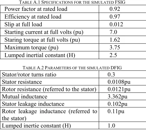
EMTDC/PSCAD. The system comprises a 300MW wind farm and a 300MW/300kV VSC transmission system based on 3-level FC Converter. For Case I, the wind farm is based on FSIG while for Case II, DFIG are used. The FSIG is simulated as two coherent lumped 150MW models whose characteristics are listed in Table A.1 in Appendix. Different torque inputs to the two FSIG are used to simulate the possible different wind speed across the wind farm and to study the impact of different rotor slips on system operation during and after AC faults. The local compensating capacitors for the two FSIG are lumped into two banks each rated at 60MVar and connected to the respective FSIG terminals permanently. Whilst for DFIG, the rotor speed has little impact on the system operation as the active and reactive powers are controlled by the rotor side converter. Thus the DFIG is simulated as one coherent lumped 300MW model whose parameters are shown in Table A.2. The grid side of the VSC Transmission system is connected to an AC source with a Short Circuit Ratio (SCR) of 3. The switching frequency for the VSC Transmission system is 750Hz which results in the dominant output harmonic frequencies being around 1.5kHz and multiples thereof due to the 3-level converter structure. One HFF rated at 60MVar is used at each end and is connected permanently to the respective networks as shown in Fig. 1.
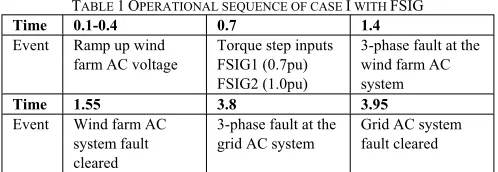
TABLE1 OPERATIONAL SEQUENCE OF CASE I WITH FSIG
Time 0.1-0.4 0.7 1.4
Event Ramp up wind farm AC voltage
Torque step inputs FSIG1 (0.7pu) FSIG2 (1.0pu)
3-phase fault at the wind farm AC system
Time 1.55 3.8 3.95
Event Wind farm AC system fault cleared
3-phase fault at the grid AC system
Grid AC system fault cleared
Table I shows the operational sequence of Case I for wind farm based on FSIG, where it is assumed that the GSVSC is fully operational before the sequence begins, i.e., the DC link voltage is controlled at rated value of 300kV and the flying capacitors are charged at 150kV prior to the start of the sequence. The simulation results are shown in Fig. 6. The waveforms shown are all in per unit values, where 1 unit is their respective rated values.
As can be seen from Fig. 6, from 0.1-0.4s, the WFVSC ramps up the AC voltage and gives smooth energization of the wind farm AC system including the FSIG. When respective torque steps of 0.7pu and 1.0pu applied to the FSIG1 and FSIG2 at 0.7s, the speeds and the slips of the two generators increase and so as the total power generated and transmitted to the grid. The AC frequency and voltage on the wind farm side keep constantly at around 1pu as the WFVSC is controlled as an infinite voltage source with constant frequency and voltage amplitude. As can be seen, the operation of the system is very smooth during power variation.
When a solid 3-phase to ground fault is applied at 1.4s on the wind farm AC network, the generated and transmitted
powers drop to zero immediately. The WFVSC is blocked in the study but the GSVSC continues to control the DC voltage. During this period, the wind turbines speed up. As DFIG2 has larger torque input than that of DFIG1, its speed increase is faster than that of DFIG1 as can be seen from Fig 6(i). After the fault is cleared at 1.55s, the WFVSC ramps up the AC voltage to re-energize the system. The frequency regulation loop is also switched on. Active power generated by the wind farm increases gradually and it is then absorbed by the WFVSC and transmitted to the GSVSC. Once the AC frequency and the rotor speeds back to their respective nominal values at around 3s, the WFVSC is switched back to infinite voltage source mode and the system fully backs to its normal operation. In the study shown, the VSC Transmission system is assumed to have 20% overload capability. System with lower overload capability requires longer time to settle down after the fault compared to system with higher overload capability as the extra energy stored in the turbine during fault is required to convert back to the system. Alternatively the pitch control of wind turbines can be used to reduce the captured energy.
When a fault is applied at 3.8s on the grid network, the transmitted power to the grid drops immediately. This cause the DC voltage to rise quickly as the WFVSC is still transmitting power from the wind farm to its DC side. This can be clearly seen from Fig. 7 which shows more detailed DC voltage waveforms during the fault. Once the DC voltage hits the up threshed of 1.1pu the WFVSC switches to DC voltage control mode with a new DC voltage reference set at 1.03pu. In this mode, the phase shift between the WFVSC output voltage and the voltage at the wind farm terminal is controlled and consequently the AC frequency increases as can be clearly seen from Fig. 6(j). The wind farm output active power is dropped accordingly due to the reduced slip of the FSIG and the DC voltage is controlled at the set value of 1.03pu as shown in Fig. 7(a). The maximum DC over voltage is around 20% which occurs at the GSVSC as can be seen from Fig. 7(b). The wind turbine speed and the AC frequency increase during the fault period. While for the GSVSC, when fault is detected the converter is switched to current limit operation and in the study the current is controlled at 0.2pu throughout the fault period.
[image:6.612.54.303.369.455.2]Fig. 6 Simulation results with FSIG: (a) Grid and wind farm AC system rms voltages; (b) Grid AC voltage waveform; (c) Wind farm AC voltage waveform; (d)GSVSC AC current; (e) WFVSC AC current; (f) Converter DC current; (g) WFVSC main DC and flying capacitor voltages; (h) Active and reactive powers from the wind farm; (i) FSIG1 and FSIG2 rotor speeds; (j) Wind farm AC system frequency.
Fig. 7 Switching of control modes during AC fault with FSIG: (a) DC voltage on WFVSC; (b) DC voltage on GSVSC
frequency are gradually reduced. Once the AC frequency backed to its rated value at around 5.1s, the WFVSC switches to infinite voltage source mode and the whole system backs to normal operation. Again, the system overload is limited to 20%. It can be seen that the system operation including the control mode switching during such fault is smooth and the performance is quite satisfactory.
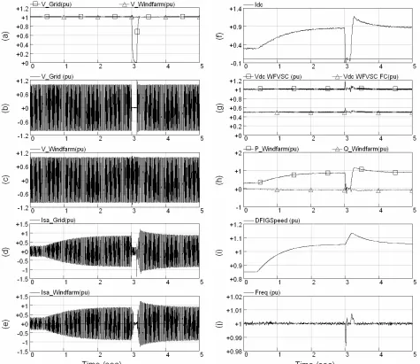
Tables II shows the operational sequence of Case II for wind farm based on DFIG. The local controller for the DFIG is based on the conventional stator flux oriented vector control [3] and the switching frequency for the rotor side converter is 1950Hz. The active power order for the DFIG is generated according to the optimal power-speed curve [2]. A HFF tuned at 1950Hz and rated at 30Mvar is connected at the output terminal of the DFIG. Synchronization of DFIG to the network is not part of this study and therefore it is assumed the DFIG has been operational prior to the start of the
sequence shown in Table II. The simulation results are shown in Figs. 8 and 9.
TABLEII OPERATIONAL SEQUENCE OF CASE II WITH DFIG Time 0.4 3 3.15 Event Torque step input
to the FSIG
3-phase fault at the grid AC system
Grid AC system fault cleared
As shown in Fig. 8, at the start of the simulation, the wind farm is generating 0.3pu active power and the speed of the DFIG is 0.85pu. When a torque step of 0.9pu is applied to the turbine at 0.4s, the speed of the generator starts to increase and so as the power generated. Similar to Case I, both the AC frequency and voltage on the wind farm side are kept at around 1pu as the WFVSC is controlled as an infinite voltage source. As can be seen, the operation of the system is very smooth during power variation. When a solid 3-phase to ground fault is applied at 3s on the grid side, similar to Case I,
the DC voltage rises quickly and this cause the WFVSC switches to DC voltage control mode with a new DC voltage reference set at 1.03pu as can be seen from Fig. 9(a). In this mode, the DFIG active power order previously generated locally according to the optimal power-speed curve is replaced by the order generated by the WFVSC controller. The DFIG output active power is dropped accordingly and the DC voltage is controlled at the set value as can be seen from Fig 9. Whilst for the GSVSC, its operation is the same as in Case I. The maximum DC over voltage is 25% which again occurs at the GSVSC as can be seen from Fig. 9(b). The wind turbine speeds up during the fault. During the study the inertial constant of the turbine/DFIG system used is substantially less than that in a real system in order to reduce the simulation time, therefore in a practical system the increase of the DFIG speed during fault would be much less than what is shown in
[image:8.612.65.540.276.687.2]Fig. 9 Switching of control modes during AC fault with DFIG: (a) DC voltage on WFVSC; (b) DC voltage on GSVSC
Fig. 8(i). Nevertheless, even with the speed increase in this study, the system operation is satisfactory.
When the fault is cleared at 3.15s, the DC voltage of the VSC Transmission system drops and the WFVSC and the GSVSC switch back to infinite voltage source mode and DC voltage control mode as shown in Fig. 9(a) and (b) respectively. As the DFIG speed is higher than pre-fault value its output power is also higher according to the optimal power-speed curve and so does the transmitted power by the VSC Transmission system. The DFIG speed gradually reduced to its pre-fault level and the system backs to its normal operation. Again, the system operation is satisfactory.
V. CONCLUSIONS
Integrating large wind farms into transmission networks using VSC Transmission systems based on 3-level FC converter has been presented in this paper. The principles of the proposed system operation and the control strategy have been described. Operations during generation variation have been demonstrated by the simulation results and they have shown satisfactory responses. System performances during three-phase AC faults have been studied and the strategies for coordinating the VSC Transmission system and wind turbines have been proposed and validated by simulations. For connecting large wind farms over long distances, the proposed VSC Transmission system has many advantages over AC connections in terms of controllability, overall cost and power loss.
VI. REFERENCES
[1] National Grid Transco, “Appendix 1, Extracts from the Grid Code – Connection Conditions", www.nationalgrid.com, February 2004. [2] Muller S, Deicke M, De Doncker RW, “Doubly Fed Induction Generator
Systems for Wind Turbines”, IEEE Industry Applications Magazine, May/June 2002, pp.
[3] Pena, R., Clare, J.C., and Asher, G.M., “Double Fed Induction Generator Using Back-to-Back PWM Converter and its Application to
Variable-Speed Wind-Energy Generation”, IEE Proc. Electric Power Applications, Vol. 143, No. 3, 1996, pp. 231-241.
[4] E. Eriksson, P. Halvarsson, D. Wensky, and M. Hausler, “System Approach on Designing an Offshore Windpower Grid Connection”, 4th International Workshop on Large-Scale Integration of Wind Power and
Transmission networks for Offshore Wind Farms, Sweden, Oct. 2003.
[5] S. M. Bolik, “Grid Requirements Challenges for Wind Turbines”, 4th International Workshop on Large-Scale Integration of Wind Power and
Transmission networks for Offshore Wind Farms, Sweden, Oct. 2003.
[6] N. M. Kirby, L. Xu, M. Luckett, and W. Siepman, “HVDC Transmission for Large Offshore Wind Farms”, IEE Power Engineering Journal, June 2002, pp. 135-141.
[7] B.R. Andersen, L. Xu, P. Horton, and P. Cartwright, “Topologies for VSC Transmission”, IEE Power Engineering Journal, Vol. 16, No. 3, pp. 142-150, June 2002, pp. 142-150.
[8] A.K. Skytt, P. Holmberg, and L.E. Juhlin, “HVDC Light for Connection of Wind Farms”, 2nd International Workshop on Transmission Networks
for Offshore Wind Farms, Sweden, March 2001.
[9] K.H. Sobrink, P.L. Sorensen, P. Christensen, N. Sandersen, K. Eriksson, and P. Holmberg, “DC Feeder for Connection of a Wind Farm”, Cigre
Synposium, Malaysia, Sept. 1999.
[10] W. Lu, and B.T. Ooi, “Optimal Acquisition and Aggregation of Offshore Wind Power by Multiterminal Voltage-Source HVDC”, IEEE Trans.
Power Delivery, Vol. 18, No. 1, Jan 2003, pp. 201-206
[11] J.P. Lavieville, O. Bethoux, P. Carrere, and T. A. Meynard, “Electronic Circuit for Converting Electrical Energy”, US Patent, No. 5726870, Mar. 1998.
[12] L. Xu, and V.G. Agelidis, “Active Capacitor Voltage Control of Flying Capacitor Multilevel Converters”, IEE Proc.- Electric Power
Applications, Vol. 151, No. 3, May 2004, pp. 313-320
[13] J. L. Thomas, S. Poullain, and A. Benchaib, “Analysis of a Robust DC-Bus Voltage Control System for a VSC Transmission Scheme”, Proc. of
the 7th AC/DC Transmission Conference, Nov. 2001.
[14] L. Xu, B.R. Andersen, and P. Cartwright, “Multilevel Converter Based VSC Transmission Operating under Fault AC Conditions”, IEE Proc. C [15] J. Niiranen, “Voltage Dip Ride Through of a Doubly-fed Generator
Equipped with an Active Crowbar”, Proc. Of NWPC, March 2004, Sweden.
VII. APPENDIX
TABLEA.1 SPECIFICATIONS FOR THE SIMULATED FSIG
Power factor at rated load 0.92
Efficiency at rated load 0.97
Slip at full load 0.012
Starting current at full volts (pu) 7.0 Staring torque at full volts (pu) 1.62
Maximum torque (pu) 3.75
Lumped inertial constant (H) 2.5
TABLEA.2 PARAMETERS OF THE SIMULATED DFIG
Stator/rotor turns ratio 0.3
Stator resistance 0.0108pu
Rotor resistance (referred to the stator) 0.0121pu
Mutual inductance 3.362pu
Stator leakage inductance 0.102pu
Rotor leakage inductance (referred to the stator)
0.11pu
Lumped inertie constant (H) 1.0
[image:9.612.318.552.457.668.2]