Collaborative support for distributed design
R.I. Whitfield, A.H.B. Duffy
Department of Design Manufacture and Engineering Management University of Strathclyde
Glasgow, G1 1XJ, UK
*Corresponding author: [email protected]
Abstract
A number of large integrated projects have been funded by the European Commission within both FP5 and FP6 that have aimed to develop distributed design solutions within the shipbuilding industry. VRShips-ROPAX was funded within FP5 and aimed to develop a platform to support distributed through-life design of a ROPAX (roll-on passenger) ferry. VIRTUE is an FP6 funded project that aims to integrate distributed virtual basins within a platform that allows a holistic Computational Fluid Dynamics (CFD) analysis of a ship to be undertaken. Finally, SAFEDOR is also an FP6 funded project that allows designers to perform distributed Risk-Based Design (RBD) and simulation of different types of vessels. The projects have a number of commonalities: the designers are either organisationally or geographically distributed; a large amount of the design and analysis work requires the use of computers, and the designers are expected to collaborate – sharing design tasks and data. In each case a Virtual Integration Platform (VIP) has been developed, building on and sharing ideas between the projects with the aim of providing collaborative support for distributed design. In each of these projects the University of Strathclyde has been primarily responsible for the development of the associated VIP. This paper describes each project in terms of their differing collaborative support requirements, and discusses the associated VIP in terms of the manner that collaborative support has been provided.
1
Introduction
For organisationally or geographically distributed design to be successful, there is a need to co-ordinate the activities of those involved. This co-ordination is there to ensure that the right thing is done for the right reason at the right time [1], and without it, unnecessary effort may be expended reworking activities that have been undertaken using information that is either immature or unreliable. Worse still, a lack of co-ordination between those involved can result with chaotic behaviour [2]. One aspect of co-ordination to make distributed designers aware that they have to collaborate or co-operate towards a common goal. This paper aims to illustrate the different approaches to providing collaborative support to distributed design teams that have been implemented within three different European Commission funded projects. The three projects have all
deal of expertise within this domain distributed across shipyards, consultancies, regulatory bodies as well as academia. These projects have aimed at providing a means of consolidating this expertise through the use of a VIP, which allows designers to share design tasks, tools, knowledge and data. This consolidated expertise should provide a competitive advantage in allowing the partners involved to design more advanced vessels than was possible without the use of the VIP. Whilst the focus of the VIP development has been towards supporting the distributed design of ships, the underlying VIP implementations have to a large extent been generic in nature, and are therefore equally applicable to other industries such as aerospace, off-shore or defence.
The Decision Support (DS) topic of the NECTISE project aims to define and implement a VIP for DS (VIP-DS) – an architecture for which is proposed within [3]. Whilst the focus and requirements for this platform differ from that within the above projects there are a number of platform management elements that have the potential for reuse: project and processes; resources, and dependencies. The aim when developing the VIP-DS is to consider the best-practice across these platforms for these management elements and re-use where appropriate. One aspect that the Decision Support topic explicitly shares with these projects is the need for collaboration within a distributed organisation or even across organisations. The lessons learned for collaboration management and visualisation within a VIP for project, process, resource and dependency management will therefore be directly applicable to the provision of decision making collaboration within the VIP-DS of NECTISE.
The platforms developed within the VRS, VIRTUE and SAFEDOR projects are discussed within Sections 2, 3 and 4 respectively. Section 5 concludes.
2
VRShips Platform
within and between organisations through the integration of these point solutions; ensure that the design problem being investigated is consistent across all of the analyses being considered; and ensure that changes are correctly propagated and that design activity is undertaken for the correct reasons.
A solution to the multi-partner collaborative design problem was realised within the VRShips platform by allowing the designers to continue using the design tools, techniques, rules and knowledge that they are familiar with, and to provide an over-arching platform that integrates the tools’ and the designers’ capabilities, and monitors, manages and co-ordinates their actions. This management is a pre-requisite for establishing an efficient and effective integrated environment between designers and systems. Whilst it does not necessarily dictate how designers perform their activities, it provides a mechanism for designers to co-ordinate their actions, provides information and guidance to aid the decision-making process, and takes action in response to others.
The VRShips platform aims to provide support to the users of the platform in order to allow them to combine the tools, knowledge and expertise of the partners involved within an environment that enables the design and evaluation of novel vessels through the combination of these through-life point solutions.
2.1
VRShips requirements
Requirements were defined at the start of the VRS project to provide a basis for developing the VRShips architecture and platform implementation. These requirements are summarised below into themes associated with the management of the VRShips project.
Integration: deliver a flexible protocol and
communication mechanism to enable disparate platform elements to integrate and co-ordinate their functionality.
Common model: provide a consistent representation
of the data defining the ship systems and consider the functional requirements of the life-phase process models as well as the requirements of the integrated tools.
Virtual interaction: provide functionality to enable:
multi-user access; configuration and use of design and simulation tools; access to the common model; visualisation of common model contents; querying of data consistency status; enactment of processes, and use of the performance modelling tool.
Inference engine: maintain the consistency between
the common and local models through the management of change propagation and conflict resolution between multiple users.
Process modelling and control: should co-ordinate
distributed activities within a virtual platform, manage the resources that are capable of performing the activities, as well as co-ordinating when and why they should be undertaken.
Simulation engine: represents the design and
simulation tools “wrapped” within the platform and should allow a through life assessment, ranging from concept development to performance trials and operational scenarios.
2.2
VRShips architecture
One of the focal points of facilitating collaboration within the VRShips platform was through the exchange of product data via the common model. Previous attempts had been made to use the Standard for the Exchange of Product model Data (STEP) and its underlying Language, EXPRESS for the exchange of ship product model data, however the number of design and simulation tools supporting STEP within VRShips were limited hence an alternative had to be found. A review of product modelling technologies can be found in [4]. A neutral data representation was sought that would meet the requirements of VRShips which was developed by considering both the different life-phase data requirements as well as the individual data requirements of the tools to be integrated. This top-down and bottom-up approach led to the development of an extensive product model schema, developed in XML that could easily be extended if required. The schema was used to develop a product data model contained within an XML database (the centralised common model). This product data model represented the minimum amount of data required (what was common) in order exchange the data that was needed between tools whilst maintaining data consistency. Additional data (that which was not common) was maintained within the individual tools distributed data models.
Design and simulation tools were integrated into the platform through the use of a “generic wrapper” that was part of the client-side user interface. One of the intentions of the generic wrapper was to minimise the development required in order to integrate a tool into the VRShips platform. Unlike the use of STEP for example where considerable effort is required to import STEP data or the use of CORBA where access to the tool’s source code is required, the generic wrapper only required the development or relatively simple input and output data converters to translate from the tools’ native format to the common model’s generic format. Once these converters had been developed, integrating any tool into the platform was a straightforward process that did not require any software development experience.
User Interface Common Model Generic Wrapper Simulation Tool AVPro Local Model In pu t C o nv e rt e r Out p ut Conv er te r SSL Com Generic Wrapper Design Tool Tribon Local Model In pu t C o nv e rt e r Out p ut Conv er te r SSL Com Generic Wrapper Design Tool AVPro Local Model In pu t C o nv e rt e r Out p ut Conv er te r SSL Com
Process Control Tool
[image:3.595.60.284.58.234.2]Resources Requirements Processes SS L C o m SSL Com Inference Engine Dependency Maps SS L C o m Performance Analysis Performance Models SS L C o m Common Model Communication Virtual Platform Communication
Figure 1. VRShips architecture
The VRShips platform was developed to allow distributed through-life design and simulation of ships across Europe. A user interface to the platform was developed as the final component of the architecture that would represent the “window to the platform” and would allow the user to co-ordinate their activities with those of others. It was intended that the user interface would allow the visualisation of the data contained within the process control tool, the inference engine, the performance analysis server and the common model.
2.3
VRShips implementation
It was established that the VRShips platform should not place any restrictions on who could use it, hence wherever possible the platform was developed in a neutral way. This was achieved through the use of Java allowing the platform to be run on any operating system.
One of the main objectives of the VRShips platform was to co-ordinate the activities of users such that the design process progresses in an efficient and effective manner. The process control tool was developed in order to facilitate this co-ordination - Figure 2.
Figure 2. VRShips – process control tool – process
view.
As a server side application, the process control tool defined processes as a series of inter-dependent tasks,
representative of a statically defined workflow. At this stage the tasks are defined without resource consideration – this information is determined later by the users via the user interface and also defines the way that users collaborate in terms of enacting the process.
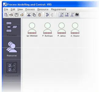
[image:3.595.341.503.228.379.2]The process control tool does however provide validation of user login, since it is also responsible for managing user accounts - Figure 3. For each user, the process control tool tracks the login status, the tasks that a user has configured as being capable of undertaking, and what tasks a user is currently committed to undertaking. A more detailed description of how the process control tool manages task allocation can be found in [5].
Figure 3. VRShips – process control tool – resource
view.
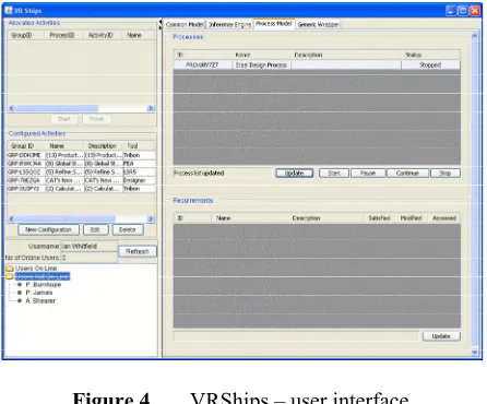
Once a user has correctly logged on, the user interface is displayed which represents the various ways in which the user can interact with the platform – for most users, this is the only part of the platform that they would generally use - Figure 4. The elements to the left of the user interface are related to the configured and allocated activities within the process control tool, as well as to other users of the platform that are either online or offline. The elements to the right of the user interface represent the different views of the data within the common model, the data dependency network and consistency status within the inference engine, the processes within the process control tool, and the generic wrapper to allow tools to be integrated into the platform.
[image:3.595.58.286.536.713.2]that the user is now capable of performing this activity. Using this approach, the individual users of the platform are responsible for proactively identifying the tasks within the processes that they are capable of undertaking and hence how they would collaborate, with the process control tool tracking the users’ capability.
Figure 4. VRShips – user interface.
Any of the processes within the process control may be enacted via interaction with the user interface. The process control tool uses a range of mechanisms [5] to determine the most appropriate user to allocate the task, and once allocated is displayed within the “Allocated Activities” section of the user interface. When the activity is started, the enactment component of the generic wrapper downloads the input data from the common model, converts it into the native format, starts the tool(s), before converting the output data into the generic format, and uploading the output data to the common model. The interaction between the user interface and the process control tool provides an implicit collaboration between the users of the platform that is co-ordinated through the enactment of the process.
The VRShips platform users can further collaborate through viewing: the state of the data within the common model; the consistency status of the data within the inference engine (which mirrors the data within the common model), and a list of the processes that are currently being managed by the process control tool.
2.4
VRShips discussion
The VRShips platform was used manage a collaborative design process across Europe for the design a novel ROPAX vessel from very early conceptual stage, through to being able to simulate a number of production and operational life-phase aspects and was subsequently successful in many of its objectives. Much of the server-side visualisation was not represented within the user interface such as the rich source of information within the process control tool - Figure 2. The result was that the collaboration for process control was achieved using textual rather than graphical information.
3
VIRTUE Platform – VIP-V
The VIRTUE project consists of five work-packages, four of which represent “virtual basins”, and the fifth aims to develop an integration platform that will combine the virtual basins into a holistic design environment. The virtual basins use design and state-of-the-art CFD code to allow the analysis of ships with respect to towing, sea-keeping, manoeuvring and cavitation to be undertaken. Like the VRShips project, the expertise associated with these four basins is distributed across Europe, hence one of the aims of the VIRTUE Virtual Integration Platform (VIP-V) was to provide an architecture that would allow designers from across both Europe and the basins to collaborate in their design activity.
3.1
VIP-V requirements
The VIP-V is required to provide management and support for all of the CFD and design tools required within an integrated CFD ship design environment. The requirements defined within the VIRTUE project reflect the different scenarios for which the platform would be used, with the main users being the basins in the project partnership and requirements influencing collaboration are summarised in the themes below:
Communication technology: should be able to
provide a reliable and secure access for internal and external users, depending on different identified user roles.
Process control: should be able to construct, modify
and run particular processes depending on different user roles. It should be possible to back-step in the process chain and repeat consecutive steps with modified data.
Project management: should provide a means to
monitor the work progress and the project manager must be able to obtain an overview at any time, and be able to inform customers on work progress upon request.
Visualisation: should allow “mock ups” of the 3D
geometry and CFD to be visualised as well as allowing collaborative visualisation for experts sitting at different computers.
Data Management: should support the
communication between the integrated tools via a storage medium (common model). A version control system should be implemented to allow the tagging of data states and the platform should supply an estimation of storage (and CPU) requirements and issue a warning if unreasonable resources are required. The platform should take care of minimizing the data transfer and should provide mechanisms for data import and export, especially for legacy data.
User Interface: should assist the user with the
navigation and progress of a project with different views depending on user roles so that viewing, reading and writing authorization should be handled according to those roles.
3.2
VIP-V architecture
the mix in operating systems that would require support: Linux, Windows, Unix and Mac (in that order of usage). However the VIP-V had a number of conceptual differences with the VRShips platform, and chiefly amongst these was in the development of the common model. It was identified early on within the VIRTUE project that some of the results from a single CFD analysis would be of the order 100MB, which would pose problems for an XML database. With multiple analyses being undertaken, an alternative solution was sought. The concept of having a centralised database holding common data with local models holding all other data was modified to an architecture where the centralised database contains Uniform Resource Locators (URLs) to the data stored within distributed FTP servers. A generic wrapper was still used to integrate the design and CFD tools into the platform. However when the generic wrapper attempted to download data, it would firstly communicate with the common model to establish where on the network the required data was. Once this had been established, the generic wrapper would communicate with the FTP server located at that URL and request the file which would be downloaded. A similar sequence of operations would be performed to upload output data with the common model being updated to indicate that a new version had been created. The architecture therefore allowed for a centralised database to store only the references to the required data, and a number of FTP servers to control access to the data for the distributed users as seen in Figure 5.
Figure 5. VIP-V Architecture.
Multiple projects containing multiple processes can be managed within the Project Server of the VIP-V. The management of user accounts was however separated from the project server with the development of a separate Admin Server. This allowed projects and user accounts to be created in isolation to each other rather than within each other as implemented with the VRShips platform. The VIP-V may be either distributed across a network as shown within Figure 5, or all operated from one machine.
3.3
VIRTUE implementation
Login to the VIP-V platform is validated by the
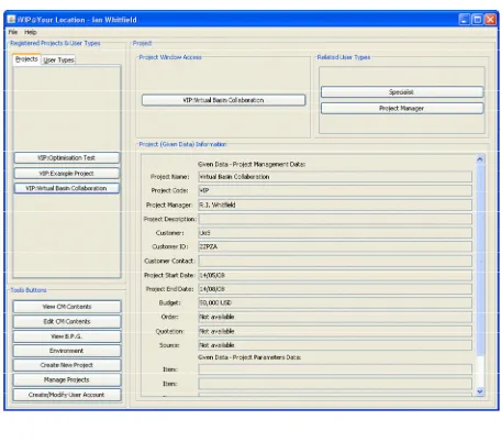
seen within Figure 6 is displayed. Despite the Project and Admin servers having their own user interfaces, the entire management of the platform may be achieved via the VIP-V user interface. When a user is created they’re given a role which may be defined as either manager and/or specialist. The different roles are provided with different functionality within the platform with managers having rights to create and modify processes for example, and specialists having rights to enact processes. The VIP-V user interface has components to display: a list of projects that the user has been registered with; buttons to control the use of the platform, and details of the selected project details.
When a user creates a project they are expected to provide the general project information that can be seen within Figure 6, as well as information relating to the processes that will be associated with the project. The process definition component of the platform is similar to the process client component seen within Figure 7, but with the provision of tools to allow processes to be constructed. Part of project definition involves allocating expertise to the tasks within the process using the user information that is contained within the Admin Server. Since more than one user is generally involved, and these users are distributed, the project definition involves detailing the collaboration that will be undertaken.
Figure 6. VIP-V user interface.
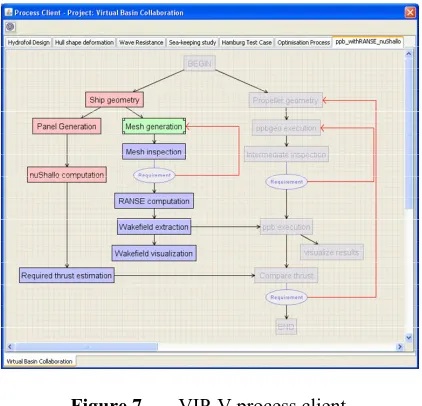
Once a project has been defined, all those users that have been allocated to the tasks within any of the processes will have the associated project automatically displayed within the user interface. Once the project is selected and the process client started the user gets a visual representation of all of the processes within the project – Figure 7, which differs from the VRShips platform where the users only had textual information relating to the activities and processes. The task state within the process client is consistent with both the Process Server and all other users working on the same project.
[image:5.595.60.281.424.599.2]example between “Required thrust estimation” and “Compare thrust”.
Figure 7. VIP-V process client.
In addition to highlighting collaboration, the process client also indicates whether a task has been completed (red), is currently being completed (green), or will be completed at some point in the future (blue). A task can only be started when preceding tasks have been completed; hence the status of the process is automatically updated for each user of the VIP-V. The process controller within the VRShips platform was proactive in allocating tasks to users, with the users reacting to the tasks that had been allocated. The philosophy within the VIP-V differs in that it is the users that are proactive in undertaking the tasks, whilst the VIP-V reacts to what the users are undertaking.
3.4
VIRTUE discussion
The VIP-V has been used to undertake a number of different design and CFD analyses by the various basins within the VIRTUE project, and has been driven by a set of requirements that have evolved as the platform has been developed. Many of these requirements were focussing towards collaborative aspects such as the automated refreshing of the process client to indicate the actions of other users. From a visualisation of collaborative activities, the process client part of the VIP-V represents a significant step forward compared to the textual views of the VRShips user interface.
4
SAFEDOR Platform – VIP-S
The primary aim of the SAFEDOR Virtual Integration Platform (VIP-S) is to provide support for Risk-Based Design (RBD) with the secondary aim of including performance, earnings and cost data within the design process. The intention is to free designers from the highly constrained design space imposed by safety regulations, and allow them to design equally safe ships through the simulation of an extensive range of different hazard scenarios. These simulations should for example allow the designer to modify egress routes to minimise
fatalities as a result of simulated fire propagation. As mentioned earlier however, the VIP-S should simultaneously allow Performance, Earnings, Risk and Cost (PERC) simulations to be undertaken for any particular design, presenting this information to the designer in such a way as to facilitate the decision making process. The VIP-S can be tailored to suit the differing PERC requirements of different types of vessels.
Expertise is required to operate both the design and PERC simulation tools, and it is clearly unlikely that all of this expertise would be possessed by one person. A need therefore exists to be able to perform this design and simulation work within a distributed sense (either geographically, or more likely organisationally), which will also allow the designers to operate in parallel. The following high-level RBD tasks were identified as being necessary for the VIP-S to provide:
• Probability analysis (frequency estimation): hazard identification and ranking, top-event selection (risk drivers) and design scenario (accident category) identification.
• Consequence analysis through enactment and evaluation of consequence analysis tools.
• Evaluation of risk together with cost, earnings and performance considerations made on the basis of the global PERC model.
• Identification and evaluation of suitable Risk Control Options (RCOs).
• Additional design activity as required.
4.1
VIP-S requirements
The above RBD tasks were used to create an extensive list of support requirements for the VIP-S, with the main points with respect to collaboration are as follows:
• RBD requires a common agreed interpretation on
the design and simulation process to reduce the risk
of not formally implementing safety regulations. • A systematic and comprehensive way is required to
address the general cost issues that are “in-built” in the design process. The key aspect is the real time
feedback to validate/update the budget or
simulations to support the evaluation.
• Tool-based design should include: a quick way to build simulations out of the data contained in the ship model; a generic mechanism to cope with commonly used tools; and a means to easily create the
required scenarios that are useful to designers.
• A common standard for data exchange between
(distributed) tools is required to reduce the
problems in transferring data or minimising the number of inputs when using different tools.
• The use of the VIP-S should enable the effective sharing and exchange of knowledge between
several designers. The VIP-S needs to address the
problems that are concerned with the fragmentation
of available tools; repetition of input and layout
for each model and analysis; usage of different
in managing design data; integration of ERP
systems associated to the design; and management
of external data (configuration control) including
subcontractors and suppliers.
Further consideration was given to the use of the VIP in terms of implementation issues arising from the above requirements. It was established that there would be between five and ten designers collaborating together at any point in time, and that the tools they would be using should be able to be used on an ad-hoc basis. This clearly contrasts with both VRShips and VIP-V, where tool usage was tightly tied to tasks within a process model. The outcome of allowing ad-hoc tool usage is a change in the way co-ordination is achieved – in principle, distributed designers could behave chaotically if either a proactive or reactive process model is not used. To achieve this need, a different collaboration mechanism was therefore required than that implemented within VRShips or VIP-V.
Despite having no conceptualisation of a process model, the VIP-S was expected to co-ordinate the design activity with respect to different projects. A VIP-S project contains information related to: project description; name of customer; project start and end dates, as well as time and resource information, shipbuilding location and a list of main suppliers. Collaboration should be supported both within and across projects. Flexibility should be also provided within a project to allow designers to operate on different versions of the design and PERC data.
Since the use of the tools within the VIP-S could be undertaken on an ad-hoc basis by designers working on the same project, but within different offices, buildings or locations, the use of a data dependency map was considered to be crucial. This map should the consistency status of design and PERC data, which should be automatically updated for all users once the status changes. This mechanism should allow distributed designers to get a consistent and up-to-date visual representation of what RBD activity has been undertaken, and also what is left to be completed. The dependency network may also be used to indicate how designers may collaborate at the data and information exchange level.
The RCOs represent a possible course of action (option) that may be taken to control the risk (as well as other PERC metrics) through the modification of the design. A RCO may be defined as a series of steps and rationale for reducing the risk, due to loss of life for example, as a result of unacceptable performance within a particular hazard scenario. The steps within the RCO are synonymous with specific design activities that may be undertaken collaboratively. An RCO may be applied to a project to attempt to control a risk; however it is the designers’ responsibility to ensure that it is enacted. Since the steps within the RCO require design or simulation tools in order for the RCO to be applied, this implies that the application of an RCO may be a collaborative endeavour.
It is expected that parametric data may be used as a basis to form the PERC metrics, and this parametric data should also be integrated within the data dependency
consistency measure, it should be further exploited within a graphical form to indicate the trade-off between the PERC metrics for example. Since a project may contain a number of different versions of the design and PERC data (and associated parametric data), these versions may themselves represent points or lines on a graph. In a similar way that the dependency network is updated to provide a collaborative view of data consistency, the graphs should be updated so that all designers may graphically visualise the changes that others are making.
4.2
VIP-S architecture
[image:7.595.313.534.447.625.2]The architecture for file exchange within the VIP-S is identical to that of VIP-V, with a centralised database storing meta-data relating to the URLs of file-based design and PERC data, which is subsequently stored on FTP servers. This file exchange architecture was chosen on the grounds of its flexibility and success within the VIP-V. The fundamental difference in architecture between VIP-S and VIP-V is in the way projects and user accounts are managed and stored. Within VIP-V, two separate server applications were created to manage these two functions. However within VIP-S, all data other than file-based data is stored within the centralised database - Figure 8. From an IT standpoint, the database within VIP-S becomes the focal point for collaboration – any type of change that a designer makes within a project is automatically updated within the database. Through the VIP-S, other designers automatically receive updates for the project they are working on via updates with the database.
Figure 8. VIP-S Architecture
consistency status, Risk Control Options, and graphs. One of the aims when defining the architecture for the VIP-S was to simplify any setup and platform administration tasks, and the use of the Database Server as an information storage area was seen as one way of achieving this.
In addition to the Database Server, the VIP-S can manage any number of FTP Servers in the same way that the VIP-V is organised. The remaining component of the VIP-S is the user interface that represents the window to the platform.
4.3
VIP-S implementation
Since the platform is intended to provide collaborative support for distributed design, it provides a login function to track those users that could potentially collaborate – illustrated by the designers distributed across a network within Figure 8. The logging in process is validated against user account details required to access the database. The user will not be allowed access to the VIP-S if the database does not contain an account with the specified login details. Once login has been validated, the user’s profile is downloaded from the database and used to configure the user interface. A number of different views are currently implemented within the user interface that relate to the management of projects, RCOs, graphs and users. The intention is to provide a modular approach to allow additional functionality to be implemented within the VIP-S.
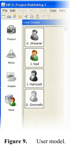
[image:8.595.113.230.493.736.2]The user interface contains information relating to the current status of the users configured to use the platform – Figure 9. This view illustrates all the users that have been configured within one instantiation of the platform. It could for example represent the users configured to work within a particular project, or across projects, or for users within an organisation or across organisations.
Figure 9. User model.
Since the users could be distributed across an organisation where no physical contact between users is available, the VIP-S provides an indication of the online
status with online users rendered in solid gray (A. Shearer and J. Hancock) in Figure 9. A user may be online but working on a different project, hence an indication is given in the use of colour to illustrate that a user is both online and currently working on the same project (J. Nail) within Figure 9. Since the online and project status of users can change dynamically, the status within the user interface is also automatically updated. The user is subsequently provided with a consistent view of other users that could potentially be collaborating within a project.
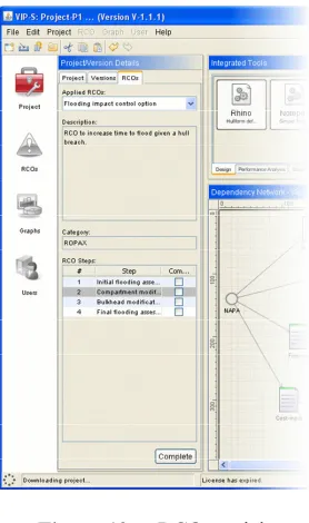
The main view that a user interacts with is the project view, shown within Figure 10. Within the VIP-S, a project consists of elements relating to: general project details; versioning information; applied RCOs, and a dependency network. These elements may individually used as a basis for collaboration.
[image:8.595.310.537.585.743.2]The dependency network represents the relationships between the data that is used to define the design problem (such as hullform, and general arrangement of a ship within Figure 10 for example), and the tools or other transformations that may be used to modify the data. Two types of data can be represented within the network – physical data files located on FTP servers associated with each of the file nodes, as well as parametric information stored within the database. The data within the dependency network contains meta-data to represent its state. When a design tool for example is used to modify the hullform, there is a potential for all data that is dependent on the hullform to be inconsistent. This consistency status is represented within the network by the colour of the node – green indicating consistency, and red indicating inconsistency. Figure 10 indicates that NAPA has been used to modify a number of files, which are all consistent with the changes made (which is assumed to be significant); however all other data that is dependent on these files has been made inconsistent. The consistency checking is propagated automatically by the VIP-S, and is done in this manner since no universal system currently exists that could check for significance of change to any type of data file. The status of the consistency of the data within the network is also automatically updated so that all users working within the same project can see what work has been undertaken, and what is outstanding.
In addition to managing consistency status, the data within the network also indicates a lock status. This is to control multiple users attempting to modify or use the same data within the network at the same time.
Once a user starts a tool, the VIP-S ensures the state of all associated data is synchronised, before locking the data and updating the network. Other platform users can immediately see the data that is being operated on. A user may however choose to use locked data, in which case the VIP-S provides them with a copy and does not allow any changes to be uploaded to the VIP-S.
The dependency network as opposed to a process model was implemented within the VIP-S resulting from the requirement to be able to perform design or simulation work on an ad hoc basis and to not be dictated by a statically defined process. The dependency network represents a consistent view of the data and tool usage that is shared across a number of distributed users.
Assuming that both the users and expertise are distributed, the use of design and simulation tools must also be distributed; hence the tool nodes within the dependency network provide an indication of the tools that each user has configured. The user always has access to the tools that they have configured – seen above the dependency network within Figure 10. However the tools are mapped to the dependency network on the basis of the function that they provide, with mapped tools using the data that is represented within the network and accessed from the common model, whereas unmapped tools only use local data.
The dependency network represents the consistency status of one version of the entire data set. Like the VIP-V, the VIP-S manages multiple versions of the data – with the different versions being represented within the version tree of Figure 10. Whereas the VIP-V manages individual versions for each piece of data, the VIP-S has an entire dataset within each version, with the consistency and lock status of the dataset potentially being different across each of the versions. Different versions and variants can be created, modified and deleted within the VIP-S either copying datasets from existing versions or using completely new datasets. Each user also sees a consistent version tree in the same way that data consistency status is automatically updated. Although not currently implemented it is also intended to illustrate within Figure 9 whether a user is working on the same version as well as the same project.
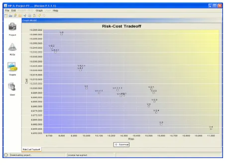
Where the project management view is used to facilitate collaboration within design and simulation activities, the graph view facilitates collaboration in terms of the management of results. As mentioned earlier, the dependency network of the VIP-S is capable of representing both file-based and parametric data. Parametric data may be used either as input to a file, or extracted from a file, and may therefore be used to parametrically define a concept. Many tools within the shipbuilding industry have the ability to take parametric data as input to define a hullform for example. The parametric data represented within the dependency network may subsequently be used to construct various different types of graphs such as that shown within Figure 11 for example. The simple X-Y graph within
[image:9.595.310.536.101.267.2]cost parameters for the dependency network within Figure 10, where each point on the graph represents a version within the version tree.
Figure 11. Graph model.
Whenever a version is either: created; modified (parametrically), or removed, the graphs associated with the project are updated. The graphs can either be shared or individual to a user with the graphs being automatically created when a project is opened. If a graph is shared amongst users any parametric modifications that other users are making to any version or variant are automatically updated on the graphs. The graphs provide a focal point to facilitate collaboration in terms of the strengths and weaknesses of the versions of the design being developed within a project.
The final collaborative view developed within the VIP-S provides guidance in the form of an RCO in terms of how performance, earnings, risk and cost may be improved for any version within a project. RCOs are created as a series of steps to follow in order to control a particular risk, and were extended to utilise the performance, earnings and cost metrics. They may be created to represent particular rationale to follow to achieve a ship design that has improved individual risk characteristics – evacuation for example, or as a general guide for a more complex network to illustrate the steps to take to get a consistent global measure of risk.
When an RCO is created, estimates are provided in terms of its potential impact on the PERC metrics, which may of course only be applicable for certain categories of design. The RCO is stored in the database for later use. If a situation later arose within either the same or different project where a potential hazard had resulted with an unacceptable risk, a database search could be undertaken to identify potential RCOs that could minimise the hazard impact. Since PERC metrics are used to define RCOs, they may also be used to improve performance, reduce costs or any combination of the metrics.
from the list. Again since the design and simulation activity is distributed, it is expected that the individual steps within an RCO may be undertaken by a number of different users.
Figure 12. RCO model.
The VIP-S does not constrain who can undertake each individual step within an RCO, but does automatically update the application of the RCO so that each user that is operating on the same version will not only see which RCOs that have been applied, but also what the status of the RCO is. Once all of the steps within the RCO have been undertaken, the RCO can be completed and removed from the version. Part of the completion process involves providing additional information relating to its relative impact to the applied version. This information is then stored with the RCO within the database and used for further refinement of the RCO’s applicability.
4.4
VIP-S discussion
The VIP-S provides many different elements corresponding to set of requirements that were developed specifically to support RBD. In each case these elements were designed with a view to support collaboration with any relevant changes being automatically updated to all interested users. The VIP-S was developed through the fusion of ideas from the VRShips platform (the dependency network of both the inference engine and the performance modelling tool), and the VIP-V (the approach to managing data and associated elements of the generic wrapper).
5
Conclusion
Three different Virtual Integration Platforms (VIPs) are described from the viewpoint of supporting collaborative design within the shipbuilding industry. The platforms have a number of aspects in common: they each require the use of design or simulation tools to progress with the design activity; they each require some mechanism for
the exchange of data; and they each require some form of co-ordination to ensure that the collaboration is undertaken effectively. Different mechanisms were implemented to facilitate co-ordination, with the user becoming more proactive in ensuring both collaboration and co-ordination. The differing requirements of the projects also resulted with different types of information being displayed (process-based or data consistency based for example) to achieve collaboration.
An architecture is being developed within the Decision Support topic of the NECTISE project for an Integrated Decision Support Environment that will be implemented as VIP-DS (Decision Support). The VIP-DS architecture aims to reuse wherever appropriate the architecture, reasoning and implementation from the three platforms discussed here in order to provide DS. Since the VIP-DS builds upon a number of concepts already implemented within these platforms [3] the lessons learned for collaborative provision across distributed users provide a useful and important starting-point for future work. Despite not specifically addressing NEC, each of the projects reviewed have aspects that allow network enabled organisational capability to be realised.
Acknowledgements
The authors would like to acknowledge the funding received to enable this research to be undertaken. The VRShips-ROPAX project was funded by the European Commission (grant number G3RD-CT-2001-00506), which is part of the Fifth Framework Programme for Research, Technological Development and Demonstration. Both the SAFEDOR and VIRTUE projects were partially funded by the European Commission (contract numbers 516278 and FP6-516201 respectively), within the Sixth Framework Programme. The opinions expressed are those of the authors and should not be construed to represent the views of either the SAFEDOR or VIRTUE partnerships.
References
1. Duffy, A.H.B. Ensuring competitive advantage with design co-ordination. in 2nd International Conference on Design to Manufacture in Modern Industry. 1995. Bled, Slovenia.
2. Hogg, T. and B.A. Huberman, Controlling chaos in distributed systems. IEEE Transactions on Systems, Man, and Cybernetics, 1991. 21(6): p. 1325-1332.
3. Whitfield, R.I., et al. An architecture for organisational decision support. in System Engineering for Future Capability. 2007. Loughborough UK.
4. Whitfield, R.I., et al., Ship product modelling. Journal of Ship Production, 2003. 19(4): p. 230-245.