Volume 5, Issue 9, September 2016
Abstract— This paper proposed to get highly door security
system, allowing only authorized users to enter the buildings but they must firstly confirm to the microcontroller that they were authorized persons for this system through designed android application via bluetooth wireless technology. If the pre-defined user name’s data matches with the data in the microcontroller, the authorized user must enter his own password to access the system and after this, he begins to control the door’s function as desire. The system allows changing the door’s lock password for the authorized users but they need to give the old door’s lock password to change with the new one that stored in EEPROM memory in microcontroller. Although the confirming step is over, if there is a wrong condition more than two times when activating the system with the user’s own password, the buzzer will generate alarm signals continuously and the system makes phone call to authorized user. Until the authorized user doesn’t confirm to the system again, giving alarm to the environment won’t stop. The main aims of this system is to eliminate carrying multiple keys for opening or closing the door, to provide higher security system compared to traditional lock and key and implement the system in practical home for security with low-cost and removes the circuit complexity. The results of the system are simulated in proteus software. In order to be precise control of AC motor speed for rolling system, PID controller is also used in only MATLAB simulation.
Index Terms—Alarming system, Arduino C programming
language, Basic4 Android software, Bluetooth wireless technology, Door security system, Motor control system with PID controller
I. INTRODUCTION
Nowadays, the use of Bluetooth technology in a smart phone today is not just for the transfer of data and files only. It can operate over unlicensed; it‟s available at 2.4GHz frequency and also can link digital devices within a range of 10m to 100m at the speed of up to 3Mbps but it depending on the Bluetooth device class. In this modern world, the criminals, terrorists, dangers and losses are increasing in people‟s daily lives. It is vital to be secure about their environment because much of the threats are concerned with the surroundings. But, many people are still using their own keys for door lock and it can be made by its specifications and hardness and can be copied by other people to enter into their building [1]. Not to access the system easily from unauthorized users, the automation and security system can be combined to overcome this problem. Therefore, double
Thida Aung, Department of Mechatronic Engineering, Mandalay
Technological University, Mandalay, Myanmar.
Kyaw Thiha, Department of Mechatronic Engineering, Mandalay
Technological University, Mandalay, Myanmar.
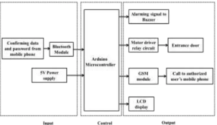
door security system with confirmation data and password based on bluetooth wireless technology will be one of the methods to get fully security for every authorized user and the passwords can be kept as secrets from those who are not allowed to access the system. So, old methods for door access system can be replaced with this system. And this system is useful and reliable for users in reality and is aimed to saving of time, energy and power consumption to access the system. The whole system is implemented on a practical home security system which requires installing it. The overall block diagram is shown in figure 1.
Fig 1. General Block Diagram of Proposed Door Locking Security System Based on Bluetooth
II. HARDWARE CONFIGURATION
This system consists of LCD display with I2C serial interface circuit, Arduino Uno microcontroller, single phase AC induction motor for simulation of motor control system, DC motor, buzzer, GSM module, and bluetooth module, Android application created by Basic4 Android software and motor driver relay circuit.
Android application is used to restrict the access of persons as input to microcontroller. Arduino Uno microcontroller is a main processing device for the system. To interface between microcontroller and mobile devices, bluetooth module makes the communication between these two. The LCD is used to display different status to the user. DC motor is used for activating door opening and closing for this system and this door function is controlled via motor driver relay circuit. Buzzer is used to give alarm signals for unsecure conditions of the system. GSM module is responsible to give phone calls to the authorized users when the system is in emergency conditions.
III. SOFTWARE DEVELOPMENT OF THE PROPOSED SYSTEM A. Software Section of the bluetooth network in the
background
Door Security with Motor Control System Based
on Bluetooth Wireless System
First checks whether Bluetooth is already enabled on the phone. If Bluetooth is enabled, the device and service discovery process will run. The software will check if there are already predefined devices stored in the phone‟s memory. If they do exist, they will be listed down for the user to select one. The program then checks to see if the selected device is in range. Now if there were no devices stored in memory, the program will search for Bluetooth-enabled devices within the area. Once discovered, these devices will be displayed on the screen and also stored in memory.
Bluetooth-compatible devices perform “inquiries” to detect and find other Bluetooth enabled devices within the area. When performing an inquiry, an application must wait to about 10 seconds for a 95% chance of detecting every device. Proper UUID (Universally Unique Identifier) and MAC (Media Access Control) address must be provided to establish the connection between the Bluetooth module of the user mobile phone and the Bluetooth module of the particular device [2][3].
Fig 2.Program Flowchart bluetooth communication with android
B. Serial (Bluetooth) designed android application The Basic4 Android Development Environment is one of the most commonly-used IDEs among software developers. It has a huge supportive community and some the most powerful plugins for all kinds of development scenarios. It will be needed for developing Android applications. The programming language for writing
Android applications is Java. Though the codes are written in Java, ultimately it will be compiled into Android-specific dex code and packaged into an archive file with the file ending “.apk”. This archive file will be put onto Android device for installation. The designed application for the door security system provides the following functionalities to the user:
Remote connection to the door‟s locks via bluetooth; requires user authentication to secure [4]
Motor‟s rotation is controlled by android application Changing password is accomplished just in android
application by the authorized users
Receives message from bluetooth module on “Log text” box.
“Sent text” box is also implemented to change the old password with the new one
The strong point of this application is that it is designed to intend only for one authorized user and the data is on the background of the application
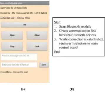
(a) (b)
Fig 3.Android application (a) GUI and (b) algorithm [5] When the user presses on the Connect menu item, it shows the user the list of known paired devices. When the user clicks on a device name, its MAC address is fetched from the map and connected to it but the connection is not established immediately. It will happen in the background of the system application. When the connection is established, the connected event will be raised. A 'Connected Successfully' parameter tells us if the connection is successful. If the connection was established successfully, the data transfer can be started.
C. Introduction of PID controller
Precise control of motors is vital to the use of motors in any application. The first step to safe control is the use of PID controller for controlling the angular velocities of AC motor. PID controller is popular because of its robustness, its simplicity, and its reusability and is either simple in theory or easy to implement. A PID controller contains a proportional gain, an integrator, and a differentiator, all of which are summed together to produce the output of the controller. The transfer function of a PID controller has the form
Volume 5, Issue 9, September 2016 PID = KP + KI/s + KD.s
(1)
Where KP = Proportional gain coefficient
KI = Integrator gain coefficient
KD= Differentiator gain coefficient
The proportional gain is used to amplify the input signal. The integrator gain is used to improve the accuracy of the control system, that is, to minimize the steady-state error (the difference between the input value and the final output value) as much as possible. The differentiator is used to increase the damping in the system, which will decrease both the peak time and the settling time of the system. When the gains of the PID are tuned, its criteria have to be followed. These criteria are
1. Less settling time (<1 second) 2. Overshoot less than 5% 3. Steady state error less than 1% 4. Rise time (<1second)
The gains of PID controller can be tuned manually or automatically. In this system, these gains parameters can be tuned by automatically and are simulated only in MATLAB software to test results before implementing hardware components.
D. Driving the transfer function of AC motor for rolling system
The differential equation and transfer function for AC motor are considerably less the fact that AC motors only have a single time constant. AC motors are described by two differential equations:
The torque (T(t)) is described by
T(t) = K.v(t) – m d/dt (θ (t)) (2)
Where K = Motor constant
v (t) = Voltage provided to the motor θ (t) = Angular position of the motor
m is described by
m "stall torque (at rated voltage)"
"no-load speed (at rated voltage)" (3)
T(s) = K.V(s) – m s θ (s) (4)
T(s) = K.V(s) – m ω(s) (5)
Where stall torque (at rated voltage) and no-load speed (at rated voltage) are characteristics of any specific AC motor.
The torque is also described by
θ(t) dt d B θ(t) . dt2 d2 J T(t) (6) Where J = Motor‟s moment of inertia,
B = Motor‟s viscous damping
θ (t) = Motor‟s angular position
By assuming zero initial conditions and then Laplace transforming each of these equations, s-domain equations are reached. The developed torque is now
T(s) = ( J(s).s2 + B.s ).θ(s) (7)
T(s) = ( J(s).s + B).⍵(s) (8)
By equating the two AC motor equations, assuming zero initial conditions, and then taking the Laplace transform of the resultant equation, the transfer function of an AC motor is found to be:
K.V(s) – m ω(s) = (J (s).s + B).⍵(s) (9) K.V(s) = (J (s).s + B).⍵(s) + m ω(s) (10) K.V(s) = ((J (s).s + B) + m) ω(s) (11) m B s J(s). K V(s) ω(s) (12) 1 s . τ Km V(s) ω(s) (13) B m K Km (14) is a constant and B m J τ (15)
is the time constant of the motor [6][7][8].
This is the transfer function that will be used for the control analysis of the AC motor.
IV. SYSTEM OPERATION
This system is designed by the combination of control system, alarming system, automation system and current wireless technology to provide the most secure door lock system compared to other traditional one. The most stunning feature of the system is that the authorized user can make the system more security by him. So, entering into the building is not easily accessed by intruders as the password of the user. It is numbers that is entered from designed android application. In order to make the system to be more secure and safety, firstly the user needs to confirm that he/she was an authorized person for this system. To store the user name that accessed the system and password they entered, EEPROM memory is responsible for it. EEPROM memory stores the update new password of authorized persons for long-term.
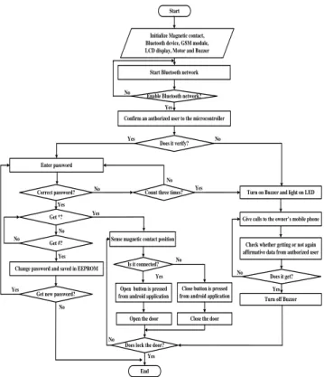
Firstly, the initialization is started for all peripheral devices. The user has to start up the bluetooth connection and
if enabled connection, whether the user is authorized or not will be checked by the system. If the authorized user will be, he must enter his corresponding update password through android application. This password will be sent to microcontroller to check whether the password is correct or not. If the checked password is correct and the user gives command „*‟ to the controller, he will access the door control functions as desired. If the checked password is wrong, the system will give chance to input password for two times more. If not so, all passwords that entered are wrong more than three times, the buzzer will activate continuously and the security system will be activated for their individual functions.
It sustains the mal-operations until the authorized user is affirmative again to the system. However, the system remains at waiting state to control the door‟s functions after the alarming system had been stopped. So, the user makes the desired control function. If the user forgot totally his updated password, the system must be reset. To access the system with default password, EEPROM program coding must be ran again to the microcontroller. If the user wants to change the old password with the new one, „#‟ command must be given to the controller then the remaining functions can be accessed as sequentially.
Start
Initialize Magnetic contact, Bluetooth device, GSM module, LCD display, Motor and Buzzer
Enter password
Correct password?
Start Bluetooth network
Enable Bluetooth network?
Confirm an authorized user to the microcontroller
Does it verify?
Give calls to the owner’s mobile phone
Check whether getting or not again affirmative data from authorized user
Turn off Buzzer Turn on Buzzer and light on LED
Does it get?
Yes No
Count three times? No No Yes No Yes Yes No Get *? Get #?
Change password and saved in EEPROM Yes No Yes
Yes No
Get new password? Yes
Sense magnetic contact position
Is it connected?
Open button is pressed from android application
Does lock the door? Open the door
Close button is pressed from android application
Close the door No Yes No Yes End No
Fig 4.Overall system flow chart
A 0 A 1 A 2 A 3 A 4 A 5 GND Vcc GND TX - 1 2 3 4 5 6 7 8 9 10 11 12 13 GND V ss R S R W E D1 2D D3 D4 D5 D6 D7 A K 16x2 line LCD display D 0 V D D V o V s s R S R W E D 2 D 3 D 4 D 5 D 6 D 7 A K D 1 D 0 V D D V o V c c G N D S D A S C L +5V A 0 A 1 A 2 +12V +12V +5V
LCD serial interface board
+ RX - 0 C828 +12V 2.7k Ohm TIP 31 TIP 31 10k Ohm 10k Ohm +12V +5V A N A L O G IN A tm e g a 3 2 8 P -P U D IG I T A L (~ P W M ) M H C -0 6 B lu e to o th M o d u le V c c G N D T X D R X D G S M m o d u le V c c G N D T X D R X D
Fig 5.Overall circuit diagram
V. HARDWARE IMPLEMENTATION OF THE SYSTEM
To control all the peripheral devices, the Arduino microcontroller can be used as the main processing controller. The system required Arduino C programming language that must be implemented to the microcontroller. The mechanism of device is to input data from android application to the microcontroller first, if there is a command that is controlled by the user, the data will be instantly sent via over a Bluetooth network then the input data is received by the HC-06 bluetooth module that connected to Arduino microcontroller.
If there is a break of the system condition, the alarming signals are produced to the environment and announced the authorized user with phone calls. GSM module and buzzer is responsible for that part of the system. The H-bridge motor driver is connected with motor to control the door opening and closing. DC motor is used to show the test and results with prototype model. The 16 x 2 line LCD display is used to show the status of the present condition of the system.
Fig 6.Hardware set up of the proposed system
VI. TEST AND RESULTS OF THE SYSTEM
Firstly, all the peripheral devices in the system are initialized and made bluetooth wireless connection between
Volume 5, Issue 9, September 2016 the microcontroller and the user‟s mobile phone. If the
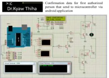
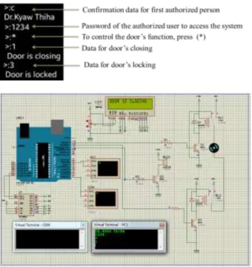
bluetooth connection is enabled, confirmation data must be sent to the microcontroller by the authorized user to access the system via designed android application. The H-bridge motor driver is connected with DC motor to control the door opening and closing for the prototype system. The LCD display is connected to pins of Port C of the microcontroller via I2C serial interface board. When the simulation runs, the LCD will be displayed the message “Door Security” that has been pre-programmed in the microcontroller then the system asks for making confirmation to access the system. It is shown in figure 7.
Fig 7.Simulation of the system confirming with authorized user to access the system
After confirmation had been successfully completed, the system allows giving password for accessing the door‟s function to the authorized user. The LCD will be cleared and “ENTER PASSWORD” message will be displayed to enter password for the user. And then, the user has to enter his corresponding password through designed android application to access the door as shown in figure 8.
Fig 8. Simulation result of entering password to access the system
Simultaneously, if the password that entered is matched with the one in EEPROM, the user can choose whether the door‟s function is activated or password changing is made. To access the door opening or closing function, a command „*‟ is sent to microcontroller. But if the user wants to change the old password, „#‟ command will give chance to change password and it is shown in figure 9.
Fig 9.Simulation result for successfully activated to the system by authorized user
Both the authorized user and the password that is entered is corrected, the door can be controlled by sending command “*” and this data is sent to microcontroller via android application to open or close the door. And the LCD displays the different status of the door‟s condition. Consequently, the system can be locked to prevent from entering by an unauthorized person. Figure 10 and 11.show the door is opening and closing by the authorized.
Fig 10. Simulation result for door opening and lock the door by authorized user
If the system is locked after opening the door, the system again return initial mode for receiving password of an authorized user in order to close the door and lock the system.
Fig 11. Simulation result for door closing and the door is locked
Figure 12.shows the changing password by sending “#” command data to the microcontroller. But the user needs to know the old password to change the new one and that new password is stored again in EEPROM memory. As soon as the new password is announced to the system, the user keeps on accessing the door‟s functions with the new one.
Fig 12. Simulation result for changing password
But, if there is a wrong condition more than three times when activating with the new password, the system generates alarm signals and give phone call to authorized user. The buzzer alarm signals won‟t stop until the authorized user confirms again to the system and the different status of the system are displayed at LCD as shown in figure 13.
Fig 13. Simulation Result for Three Times Wrong Password and generating alarm signals
VII. SIMULATION RESULTS OF THE MOTOR CONTROL SYSTEM A. Motor parameters specification
Technical data of the AC motor from KALATA Company
Model: M600D (D: single-phase)
Speed: 4.8 rev/min
No-load speed:1500 rpm
Operation voltage: single phase 220 -240 V
Operation current: 2.5 A Power: 370 W Torque: 420 Nm Gear ratio: 20:25 Height of load (h): 3.6576m Length of load (b): 5.1308m Breadth (b): 0.01950m Constant K: 0.5 (Nm) 2 s/A Bmotor : 7.33 Nms
Moment of inertia (I): 10 Nms2
B. Calculation the desired velocity for AC motor AC motor transfer function will be:
Volume 5, Issue 9, September 2016 m B s I(s). K V(s) ω(s) (16) = 2.67 7.33 s 10 0.5
The desired angular velocity will be:
ω (s) = 60 π 2 x 4.8 = 0.5026 rad/s Vout = Ktech x ω(s) (17) Ktech = ω(s) Vout = 0.5026 220 = 437.724
C. Drag disturbance force for control system
Fd = 0.5 x air density x v2 x Cd x A (18)
Where: Air density = 1.2 kg/s2
Velocity of load (V) = 0.059 m/s Coefficient of drag (Cd) = 0.35
Frontal area (A) = 5.1308 x 0.01905 = 0.09774147 m2 Fd = 0.5 x air density x v2 x Cd x A = 0.5 x 1.2 x 0.0592 x 0.35 x 0.09774147 = 71.45 x10⁻⁶ N T = Fs (19) = 71.45x 10-6 x 0.059 = 4.2155x x10-6 Nm D. Simulation result of the motor control system
Fig 14. Block diagram of the AC motor with dead based response
Td (s)
PID controller Motor constant KMotor constant K _
m m Noise Ktech Ktech + -Tm(s) TL(s) ++ 1/Js+B
Back emf constant
ὼ(s)
ὼ(s) Input
Voltage
Fig 15. Block diagram of the AC motor with PID controller
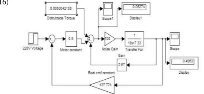
Fig 16. Simulink model of AC motor for dead based response
Noise gain is added to the system instead of coming distrubtance. And this output response is not equal to the desired input . So PID controller is used to be equal the actual response with the desired input.
Fig 17.Simulink model of AC motor but with PID controller
The PID gains can be tuned by automatically and with this gains, the rise time (0.00516s), settling time (0.0139s), response time (0.00745 sec) and percent overshoot (4.32%) can be satisfied.
Figure 18. Simulation results of step response for AC motor with PID controller for P = 0.129601476209859, I= 3.47496931882432 and D = -0.000227364246700562
VIII. CONCLUSION
The system was able to actuate a pin to open or close the door from a short distance away by just pressing a button on a smartphone. In future, the designed android application should offer assistance in controlling more doors, windows and basic home electronic appliances. Motor control system with PID control algorithm should also be considered by choosing the suitable controller gains to get the desired angular velocity for the completeness of the system.
Moreover, the system provides the reliable operation within reasonable cost and removes the system complexity. The system is designed in user-friendly interface on Window and Android GUI provides simple control by any user.
The whole system is implemented on a practical home security system which requires considerable effort to install it. Consequently, the system is also applicable for commercial purposes due to versatile ways of security and controllability.
As future work, using biometric methods such as finger prints, the iris, the facial recognition and voice, the system is to be more completeness. The camera can also be used to capture the image of intruders that try to break the system. All the future work is expected without spending extra cost, in addition to be more reliable and get better security.
ACKNOWLEDGMENT
First of all, the author is very thankful to Dr.Myint Thein, Rector of Mandalay Technological University, for his encouragement, invaluable permission and his kind support in carrying out this paper work and the author deeply grateful express to her parents for their support and encouragement to attain her destination without any trouble.
Special appreciation and thanks to Dr.Kyaw Thiha (Associate Professor), Department of Mechatronic Engineering from Mandalay Technological University of Myanmar for providing the invaluable knowledge and the necessary guidance as well as encouragement in completing this paper. The supervision and support truly help the progression and smoothness of this research.
REFERENCES
[1] Mohd Fidaus Bin Mond Bahamam: Design of Security Access
Door System, May, 2009.
[2] Jianping CAI, Jianzhong WU, Minghui WU, Meimei HUO, "A Bluetooth Toy Car Control Realization by Android
Equipment ", 2011 International Conference on
Transportation, Mechanical, and Electrical Engineering (TMEE), pp:2429-2432.
[3] Qin Y ong, Luo Hao, Han Junhua, "The Design of Grading Software System Based on Bluetooth in Android ", 2013 8th International Forum on Strategic Technology (IFOST), pp: 16-19.
[4] Shiu Kumar, “Ubiquitous smart home system using android
application”, International Journal of Computer Networks & Communications (IJCNC) Vol.6, No.1, January 2014
[5] N.H. Ismail, ZarinaTukiran, N.N. Shamsuddin, E.I.Sadon,
“Android-based Home Door Locks Application via
Bluetooth for Disabled People”, 2014 IEEE International Conference on Control System, Computing and Engineering, 28 - 30 November 2014, Penang, Malaysia
[6] D.K. Anand, Introduction to Control Systems. New York: Pergamon Press Inc., 1974, p. 34-37.
[7] Robert H. Bishop, Richard C. Dorf, Modern Control Systems,
9th ed. Upper Saddle River, NJ: Prentice-Hall, 2001, p. 52-56,
227-231.
[8] Brian Bouma, “Overview and Control of DC and AC Motors”, Calvin College in Grand Rapids, MI 49546 USA (e-mail: [email protected]).