PARAMETER
‐
PROPERTIES
RELATIONSHIP
OF
THIN
PLATE
WELDING
BY
COLDARC
TECHNOLOGY
MUHAMMED
SYAMEEL
BIN
AYOB
B051310331
PARAMETER-PROPERTIES RELATIONSHIP OF THIN PLATE
WELDING BY COLDARC TECHNOLOGY
This report is submitted in accordance with requirement of the University Teknikal
Malaysia Melaka (UTeM) for Bachelor Degree of Manufacturing Engineering
(Manufacturing Process) (Hons.)
by
MUHAMMED SYAMEEL BIN AYOB
B051310331
941217-03-6413
FACULTY OF MANUFACTURING ENGINEERING
UNIVERSITI TEKNIKAL MALAYSIA MELAKA
BORANG PENGESAHAN STATUS LAPORAN PROJEK SARJANA MUDA
Tajuk: PARAMETER-PROPERTIES RELATIONSHIP OF THIN PLATE
WELDING BY COLDARC TECHNOLOGY
Sesi Pengajian: 2016/2017 Semester 2
Saya MUHAMMED SYAMEEL BIN AYOB (941217-03-6413)
mengaku membenarkan Laporan Projek Sarjana Muda (PSM) ini disimpan di Perpustakaan Universiti Teknikal Malaysia Melaka (UTeM) dengan syarat-syarat kegunaan seperti berikut:
1. Laporan PSM adalah hak milik Universiti Teknikal Malaysia Melaka dan penulis. 2. Perpustakaan Universiti Teknikal Malaysia Melaka dibenarkan membuat salinan
untuk tujuan pengajian sahaja dengan izin penulis.
3. Perpustakaan dibenarkan membuat salinan laporan PSM ini sebagai bahan pertukaran antara institusi pengajian tinggi.
4. *Sila tandakan (√)
SULIT
TERHAD
(Mengandungi maklumat yang berdarjah keselamatan atau kepentingan Malaysiasebagaimana yang termaktub dalam AKTA RAHSIA RASMI 1972)
(Mengandungi maklumat TERHAD yang telah ditentukan oleh organisasi/ badan di mana penyelidikan dijalankan)
TIDAK TERHAD
Disahkan oleh:
MUHAMMED SYAMEEL BIN AYOB
Alamat Tetap: Cop Rasmi:
PT 678 KG. KEDONDONG, JLN KOTA TERAS, KOTA JEMBAL 16150 KOTA BHARU KELANTAN.
Tarikh: Tarikh:
DECLARATION
I hereby, declared this report entitled “Parameter-properties relationship of thin plate
welding by coldarc technology” is the result of my own research except as cited in
references.
Signature : ………
Author’s Name : MUHAMMED SYAMEEL BIN AYOB
APPROVAL
This report is submitted to the Faculty of Manufacturing Engineering of Universiti
Teknikal Malaysia Melaka as a partial fulfilment of the requirement for Degree of
Manufacturing Engineering (Manufacturing Process) (Hons). The member of the
supervisory committee are as follow:
………...
ABSTRAK
Tujuan kajian ini adalah untuk mengetahui sifat parameter kimpalan plat yang nipis
dengan ketebalan yang berbeza oleh “ColdArc” teknologi. Kimpalan ini telah dijalankan
oleh mesin robot automatik Kimpalan Arka Logam gas (GMAW). Proses kimpalan
GMAW dilakukan dengan menggunakan wayar pengisi jenis ER70S-6. Perbezaan
parameter kimpalan digunakan dan akan dikimpalkan pada spesimen. Set parameter telah
direka oleh Minitab 16. Specimen pusingan bersama dengan ketebalan berbeza telah dikaji
dengan menganalisis ujian tegangan, ciri-ciri micro-kekerasan dan analisis kumai kimpalan.
Ujian tegangan, ujian micro-kekerasan Vickers dan ukuran kumai kimpalan telah
dijalankan. Kombinasi voltan kimpalan, arus kimpalan, dan kelajuan kimpalan yang boleh
membentuk input haba dengan menggunakan formula, yang mana hasilnya dapat
bandingkan dengan ujian tegangan dan ciri-ciri micro-kekerasan. Tambahan pula, data
akan dianalisis dengan menggunakan kaedah Taguchi untuk mencadangkan satu kimpalan
parameter pengoptimuman untuk kimpalan plat jenis nipis oleh teknologi “ColdArc”. Hasil
dari pengoptimuman menunjukkan bahawa kekuatan tertinggi yang diperolehi 241.7MPa
adalah apabila arus kimpalan, voltan kimpalan dan kelajuan sekurang -70V, 17.6A dan 0.6
mm / min, masing-masing. Di samping itu, kekerasan yang tertinggi yang diperolehi
229.6HV apabila 75A arus kimpalan, 7.5V voltan kimpalan dan 0.8 mm / min kelajuan
ABSTRACT
The purpose of this study was to understand the parameter-properties relationship
of thin plate welding with dissimilar thickness by “ColdArc” welding. This welding was
conducted by automated gas metal arc welding (GMAW). The GMAW welding process
performed by using ER70S-6 filler wire. The specimen was welded by using different
parameters of welding. The set of parameters was designed by Minitab 16. Specimen of lap
joint with dissimilar thickness were studied by analyzing the tensile properties,
microhardness properties and weld bead dimension. Tensile test, Vickers microhardness
test and weld bead dimension were conducted. The combinations of welding voltage,
welding current, and welding speed in which can form the heat input of the process were
employed in this study. Tensile testing and microhardness properties were then compared.
Furthermore, data was analyzed by using Taguchi method to suggest an optimization of
welding parameter for thin plate welding by “ColdArc” technology. The result showed that
the highest strength that was 241.7MPa was obtained when welding current, welding
voltage and speed were at 70V, 17.6A and 0.6mm/min, respectively. In addition, the
highest hardness was obtained at 229.6HV when 75A welding current, 7.5V welding
DEDICATION
Only
my beloved father, Ayob bin Ahmad
my appreciated mother, Che Dzaleha bt Saad
my adored sister and brother, Syuhada and Syahidan
for giving me moral support, money, cooperation, encouragement and also understandings
ACKNOWLEDGEMENT
In the name of ALLAH, the most gracious, the most merciful, with the highest
praise to Allah that I manage to complete this final year project successfully without
difficulty.
My respected supervisor, Profesor Madya Dr Nur Izan Syahriah Binti Hussein.
Her kindness, unwavering patience and mentorship guided me through the process, her
easily understood explanations and open mind allowed me to grow and learn in such a
way that I am now a better researcher.
Last but not least, I would like to give a special thanks to my best friends who
gave me much motivation and cooperation mentally in completing this report. They
had given their critical suggestion and comments throughout my research. Thanks for
the great friendship.
Finally, I would like to thank everybody who was important to this FYP report,
TABLE OF CONTENTS
Abstrak i
Abstract ii
Dedication iii
Acknowledgement iv
Table of Contents v
List of Tables viii
List of Figures ix
List of Abbreviations xi
List of Symbols xii
CHAPTER 1: INTRODUCTION
1.1 Background 1
1.2 Problem Statement 1
1.3 Objectives 2
1.4 Scope of Project 2
1.5 Significant Study 3
1.6 Activity Planning 3
CHAPTER 2: LITERATURE REVIEW
2.1 Welding Process 4
2.1.1Arc Welding 5
2.1.2Gas Metal Arc Welding (GMAW) 6
2.1.3Thin Plate Welding 7
2.2 Innovation of Thin Plate Welding 8
2.2.1 Tandem Welding 9
2.2.2 TIME Welding 10
2.2.3 2.2.3 Cold
Metal Transfer(CMT) 11
2.2.4 Surface Tension Transfer(STT) 12
2.2.5 ColdArc 13
Welding of Thin Plate Steel 16
2.5.1 Type of Joints 16
2.5.2 Dissimilar Thickness 17
2.5.3 Application 18
Welding Parameter 19
2.6.1 Welding Current 19
2.6.2 Welding Arc Voltage 19
2.6.3 Welding Speed 20
Mechanical Properties 20
2.7.1 Tensile Testing 21
2.7.2 Hardness Test 22
2.7.3 Weld Bead Analysis 22
2.4 Cold Rolled Steel Sheet and Its Properties 15
2.5
2.6
2.7
CHAPTER 3: METHODOLOGY
3.1 Overview 23
3.2 Materials Preparation 26
3.2.1 Cold Rolled Mild Steel Sheet 26
3.2.2 Filler Rod 26
3.3 Equipment Setup 27
3.3.1 Machine Setup 27
3.3.2 Jigs and Fixture 27
3.3.3 Machine Parameter 28
3.4 Design of Experiment (DOE) 28
3.4.1 Parameter & Respond Variable 29
3.4.2 Selection in Experiment Design 29
3.4.3 Welding Parameter Setup 30
3.5 Experimental Setup 30
3.5.1 Cutting Process 30
3.5.2 Welding Design 31
3.6 Testing 31
3.6.1 Tensile Testing 31
3.6.2 Micro Vickers Hardness Test 32
CHAPTER 4: RESULT AND DISSCUSION
4.1 Introduction 33
4.2 Finding and Data Analysis on Tensile Strength 34
4.3 Taguchi Method Analysis for Tensile Strength 36
4.4 Finding and Data Analysis on Hardness Test 38
4.5 Optimization of Welding Parameter 43
4.6 Discussions on Heat Input and Weld Bead 44
CHAPTER 5: CONCLUSION AND RECOMENDATION
5.1 Conclusion 46
5.2 Recommendation 47
REFERENCES 48
APPENDICES
A Gantt Chart of PSM I 53
B Gantt Chart of PSM II 54
C Weld Bead Dimension 55
LIST OF TABLE
2.1 Chemical composition of ASTM A1009 16
3.1 The selection of respond and variable for the design of the experiment 29
3.2 Three variable parameter from Taguchi method. 30
4.1 Constant Parameters. 34
4.2 Design of experimental parameter and result for the average tensile 34
strength.
4.3 Analysis of Taguchi method for tensile strength. 36
4.4 Design of experimental parameter and result for the average 39
Hardness test.
4.5 The analysis data from Taguchi method for hardness test. 40
LIST OF FIGURES
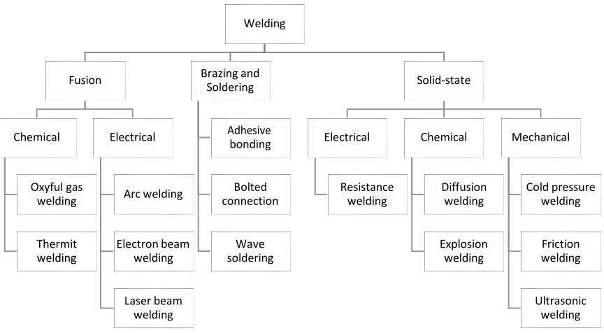
2.1 Classification of Welding 5
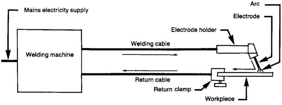
2.2 The Arc Welding Circuit 6
2.3 Illustrate of Gas Metal Arc Welding 7
2.4 Type of distortion that occurs during welding process 8
2.5 Classification of Welding Process 9
2.6(a) Tandem welding’s torch produced by Lincoln Electric 10
2.6(b) Robotic welding for Tandem welding 10
2.7(a) The differences of weld beads between conventional GMAW 11
and TIME welding
2.7(b) TIME welding machine from Fronius 11
2.8(a) The schematic of Cold Metal Transfer (CMT) welding 12
2.8(b) The principle of CMT process and perspective of its one cycle 12
2.9(a) The machine that organized the STT welding 13
2.9(b) The principle of STT process and perspective of its one cycle 13
2.10(a) The comparison of the waveform between conventional and 15
coldarc welding
2.10(b)The power during ignition between the Cold Arc process and 15
standard short arc
2.11 Type of joints for welding 17
2.12 Tailored blank for dissimilar thickness 17
2.13 The application of tailored blank weld for different thickness 18
at the vehicle
2.14 The relationship between stress-strain curves in tensile testing 21
3.1 Design of process flow 25
3.2 Filler rod ER70S-6 mild steel with copper coated 26
3.3 The Robotic Arm of Gas Metal Arc Welding (GMAW) 27
3.4 Jigs for thin plate welding 27
3.5 Smart Pad at Robotic Arm 28
3.7 Lap joint schematic 31
3.8 Grinding Machine for the specimen 32
3.9 Stereo Microscope 32
4.1 The relationship between 9 specimens with average tensile strength. 35
4.2 The main effects plot for S/N ratio of tensile strength 37
4.3 Comparison between welding current and tensile strength when 38
welding speed is constant.
4.4 The relationship between 9 specimens with average hardness. 40
4.5 The main effect plot for S/N of hardness test. 41
4.6 Comparison between welding current and hardness when the welding 42
voltage is constant.
LIST OF ABBREVIATIONS
ASTM - American society for testing and materials
AWS - American Welding Society
CMT - Cold Metal Transfer
DOE - Design of Experiments
EDM - Electrical discharge machine
GMAW - Gas Metal Arc Welding
HAZ - Heat affected zone
STT - Surface Tension Transfer
TIME - Transfer Ionized Molten Energy
LIST OF SYMBOLS
% - Percent
o - Degree
x - Multiply
A - Ampere
mm - Millimetre
kg - Kilograms
mm/min. - Millimetre per minute
kN - Kilo newton
V - Voltage
1
CHAPTER 1
INTRODUCTION
1.1
Background
Recently, the technology of arc welding was improved to get a perfect joining. These
technologies are intended to solve problem during the welding process. One of that, ColdArc
technology. Thin plate parts are normally used in automotive sector where in assembly part the
ColdArc technology is introduced to save the mass production without lose the quality (Miranda
et al.
,2011)
ColdArc technology is one of the techniques that used by Gas Metal Arc Welding (GMAW)
process but the modification in parameter sector where can produce the particularly low level
of heat during welding process with specific filler rod. With this advantage, the thin plate can
be welded with strong bond thus produce a lightweight of the automotive part with the high-
strength thin plate. Therefore, it can save costs and protect the environment (Goecke, 2005)
In joining, the suitable level of parameters are needed to get a strong joint of parts. Even,
the joint is complete there is might be a defect and the joint is not tough especially in different
thickness. Therefore, the best parameter is required in this study to avoid the failure. Besides,
the distortion during welding is different when the welding technique is different.
1.2
Problem Statement
In automotive industry, the assembly part is one of the most parts that needs high
strength joint, proper selection of parameters is crucial. According to Nuraini
et al.
(2014), the
study states that by getting the correct parameter the robotic welding will become precision and
the quality of the product will increase. Next, according to Yan
et al.
(2015) it states that the
energy ingestion is condensed and the thermal efficient is enhanced when the parameter of
welding is improved. The welding current and welding speed give a huge impact on a parameter
in order to decrease the energy ingestion and improved thermal efficient. In Dean and Hidekazu
(2007) studies thin plate structure are easy to buckling when high heat input give on it. It has a
significant influence in order to make welding distortion. Therefore, the ColdArc technology is
one of the most inexpensive methods of joining process especially tailored blanks at automotive
parts. The combination of dissimilar thickness is needed nowadays in automotive
manufacturing. So, in this experiment will investigate about the current, voltage and welding
speed parameter with its properties to a dissimilar thickness of thin plate operate by ColdArc
Technology.
1.3
Objective
The objectives of this study are:-
a)
To study the effect of welding parameters to the properties of cold rolled mild steel
sheet with dissimilar thickness, welded with GMAW ColdArc technology.
b)
To suggest the optimum set of parameters.
1.4
Scope of Project
In this study, the material used was cold rolled steel sheet with dissimilar thickness (1
mm and 0.8mm). The experiment concentrated on the parameter of ColdArc welding and its
3
joining was lap joint and the weld joining with different thickness. This experiment started with
literature review. Determined the GMAW parameter by using the design of the experiment, the
Taguchi method type with 3 level and 3 factor, testing for this experiment were tensile testing
and micro-hardness.
1.5
Significance of Study
This study will benefit to the car manufacturer where applied the welding on the
dissimilar thickness metal plates. This study also gives advantage to the car manufacturer to
save the cost on welding process because consist one replication to joining dissimilar thickness
plate. Besides that, the low current usage also can gain from this study thus, can save the cost.
1.6
Activity Planning
CHAPTER 2
LITERATURE REVIEW
This chapter reviews on the development of welding, cold arc technology, type of weld
material and its properties. The descriptions are based on the collected data and information
from some reference through the article, books and internet searching.
2.1
Welding Process
Welding is one of the techniques that makes metal joint together through amalgamation
to become unified whole where amalgamation is defined as joining two materials to become as
one piece. This technique happens either heat or pressure or both (Liu, 2010). According to
American Welding Society (AWS) welding is existed in variation which including arc welding,
gas welding, brazing, also the soldering. This variation can be categories into three such as
5
Welding
Fusion Brazing and
Soldering Solid‐state
Chemical Electrical Adhesive
bonding Electrical Chemical Mechanical
Oxyful gas
welding Arc welding connectionBolted Resistancewelding Diffusionwelding Coldwelding pressure
Thermit
welding Electronwelding beam solderingWave Explosionwelding weldingFriction
Laser beam
welding
Ultrasonic
[image:22.612.98.530.78.316.2]welding
Figure 2.1: Classification of Welding (Liu, 2010).
Figure 2.1 shows the classification of welding which in basic. From that, the advantages
of welding can be described based on the cost effectiveness. The metal that has been joint is
strong and tight, also its process can be automated and mechanised. The application of these
process widely used in making motor car chassis, boilers tanks and steel structures. On the other
hand, it also has the weakness where the structures of welded place can be changed by distortion
and internal stresses. Besides, heat affected zone (HAZ) is formed and it creates a permanent
joint (Kah
et al.,
2013).
2.1.1
Arc Welding
In Arc welding, its principle commonly called “stick electrode” where the arc welding
is based on the electric circuit. When the electrode and workpiece are nearest to connected the
together and to melt the tip of the coated electrode. The electrode performed as a filler material
[image:23.612.90.547.154.325.2]which mixed with the melted base material to seal the joint (Vural, 2014).
Figure 2.2: The Arc Welding Circuit (Vural, 2014).
Figure 2.2 illustrates the arc welding circuit. According to Vural (2014), the existing of
a weld between metals is formed when the electrode connected nearest to the workpiece, then
the arc struck between the workpiece by consuming the filler metal. The arc immediately melts
a piece of the base metal while the heat created, resulting in the formation of a weld pool.
2.1.2
Gas Metal Arc Welding (GMAW)
Gas metal arc welding is a welding process that melts and joint metal through heating
them to their melting point with the arc placed between a continuously fed filler wire electrode
and the metals. Shielding of the arc and molten weld pool is usually by using an inert gas like
argon and helium. This process is well established a semi-automatic process. It also gives less
distortion and no slag removal, associated with accurate jigs and fixture. GMAW can give a
7
Wahab (2014) discussed that GMAW is operated by the automated feeding of a
continuous, simple and expandable electrode that protected by an externally supplied shielding
gas. It shows schematically in figure 2.3. During the welding process, all material went through
in high temperature then, reacted with oxygen and nitrogen thus, the elimination of air from the
weld zone occurred by shielding gas. In this process, the arc is struck by scratching the electrode
on the workpiece during the welding process. Electrode wire diameters ranging from 0.8 mm to
6.5 mm are commonly used in GMAW, the size depending on the thickness of the parts being
joined and the desired weld metal deposition rate. The gun guides the consumable electrode
[image:24.612.180.451.294.522.2]conducts the electrical current and directs shielding gas to the workpiece.
Figure 2.3: Illustrate of Gas Metal Arc Welding (AWS, 2001).
2.1.3 Thin Plate Welding
Welding innovation is generally utilized as a part of shipbuilding and cars industries.