Retrieval Number: B10751292S19/2019©BEIESP
MIMO Reconfigurable Antennas for Wi-Fi 2.4 GHz
Communication.
Sandeepkumar kulkarni, Raju Yanamshetti
Abstract: We are living in the era of wireless communication. From accessing Internet through smartphones and Wi-Fi, changing TV channels with remote controls, using wireless computer peripherals like mouse, keyboards and headphones to mobile body area networks for keeping track of heart rate, blood pressure and body temperature, applications of wireless communication is everywhere. The most frequent and common use of wireless communication is mobile phones or cellular phones which uses the radio waves to carry data from one place to another. Though there are many advantages of wireless communication which makes it so popular, there are two most significant challenges in implementing a wireless communication system: multipath propagation and limited information rate. The concept of multipath propagation refers to travelling of wireless signal to the receiving antenna via different paths in space resulting in inter-symbol interference and fading. This phenomenon leads to failure of maximum use of the bandwidth resulting in low information rate. The problematic event of multipath propagation can be exploited by using more than one antenna (MIMO) in the sending and the receiving side. Multiple sending antennas use the concept of space diversity by sending same data signal through different path based on the fact that different version of the same signal will be received by the receiver increasing quality and reliability of the received data signal.Though in the current usage scenario, MIMO actually exploits multipath propagation concept for carrying more than one data stream over the same radio signal. One of the most important factors that influence the efficiency of MIMO antenna systems is the design layout of multiple antennas. Microstrip antennas, having small height and width, low cost, low weight and small volume can be a suitable candidate for being used as MIMO. The wireless performance of locally limited wireless communication systems such as Bluetooth and Wi-Fi using 2.4 GHz unlicensed band can be increased significantly by incorporating the advantages of MIMO and microstrip antenna technology. In this paper, the performance of MIMO Microstrip antenna using OFDM technique for 2.4 GHz communication has been evaluated.
Index word: Dielectric constant, MIMO, Microstrip antenna, OFDM Technique, Wireless communication, 2.4GHz,
I. INTTRODUCTION
Wireless communication is in the verge of technological evolution as we are approaching towards adjusting ourselves with very high speed of Internet as we move from 4G to 5G communication. Nowadays, communication plays a very significant role in our life and has been made possible by huge advancement from 1G to 5G communication [1]. It has made our habits so bad such that slow access speed even for a very short interval of time is not tolerated by us. This high data rare feature has made current wireless communication technology much popular and is reflected by constant and growing number of users.
Revised Manuscript Received on December 12, 2019.
Sandeepkumar kulkarni, VTU-Belgaum, Ph.D, Electronics and Instrumentation .
Dr. Raju Yanamshetti kulkarni, Ph.D, Electrical Engineering, Jadhavpur University.
The most common and frequent use of local wireless communication is Wi-Fi technology for the purpose of accessing any type of document, audio, video from Internet through smartphones, tablets or laptops. From 2018 to 2019, there is a rapid 82% increase in mobile data traffic as number of smartphone users are growing in India and China [2]. A significant portion of this mobile traffic is generated in indoor environments or in short range communications with the help of Wi-Fi.Due to emergence of various new applications, the consumption of traffic is growing rapidly. But to accommodate this high demand of data traffic from many users the corresponding data rate should also be high requiring more of scarce resources like spectrum and energy. Keeping the user’s demands of increased data rate and low frame error rate for 3G and 4G communication in mind, the enabling technology behind Wi-Fi which is IEEE 802.11ax needs to enhance the information rate and area throughput in highly populated Wi-Fi zones [3].
The most commonly used radio bands by Wi-Fi are 2.4 GHz and 5 GHz. Each band is comprised of many channels where transmission by many networks can use a single channel using time sharing mechanism [4]. For using 2.4 GHz and 5 GHz spectrum, no license is needed to be acquired. The observation is that mobile or tablet consumes 40% to 90% data while functioning in unlicensed spectrum [5].
As number of devices co-existing and functioning in 2.4GHz ISM band (Industrial, scientific and medicalradio bands) is rapidly increasing, the packet collision rate due to signal interferences increases resulting in low information rate [6, 7]. For example, devices accessing Internet through WI-FI use the same 2.4 GHz band used by devices accessing ZigBee and Bluetooth technology. As a result, higher online streaming speed, large file downloading, handling of more devices and greater range of access points required to achieve faster local wireless communication in the future can be hindered by the low information rate due to mutual interference.
The challenges of providing high data rate and error free communication in the context of limited bandwidth of wireless communication can be mitigated using MIMO microstrip antennas. The three most significant gains that can be achieved using MIMO antennas are array gain, gain in space diversity and spatial multiplexing [9].
The concept of array gain actually indicates the increase in the power of the transmitted signal by the aid of multiple antennas in comparison to single I/O antenna system. As the information signals at the receiver are combined logically, there is an increase in the Signal-to-Noise ratio(SNR) at the receiver which is a factor of number of antennas at the receiver. This increase in SNR in turn increases the coverage area and range of wireless system.
As it is quite natural that the signals at the receiver fade away, transmitter MIMO can mitigate this effect by transmitting multiple independent copies of the signal with respect to space, frequency or time. The basic idea is that with the growing number of independent signals received, the probability that at least one of the received signals does not undergo intense fading will become high. This in turn amplifies the quality of the signal by reducing bit errors.
The most significant property of MIMO system is spatial multiplexing. The high data rate to be achieved can be implemented by transmission of many independent data signals with respect to limited bandwidth and constrained channel properties. A large number of antennas can be aided to provide service to many devices concurrently in limited bandwidth environment towards significant increase in information rate [10].
The above advantages of MIMO system can be made available to devices with the aid of microstrip antennas. The benefits of microstrip antenna that can be very much helpful in designing MIMO systems are low cost, light weight, easy fabrication capability, low power handling ability, and reduced sizeand all-directional radiation in the horizontal plane [11] which is very much suitable to be used in mobile hand held devices. However, there are still some problems that can be encountered using microstrip antennas like restricted and limited bandwidth, offering of limited gain, low efficiency due to loses in dielectric substance and the conductor, high ohmic loss etc. [11]. Not all but some of these issues can be resolved by appropriate designing of microstrip array.
One of the biggest application areas of implementing microstrip antennas is wireless local area network operating in 2.4 GHz and 5 GHz. Wi-Fi usually operates in 2.4 GHz and 5 GHz band. Due to wide use of mobile phones, 2.4 GHz band has become overcrowded and lead to interference being directed towards low information rate [12]. 5 GHz band, mostly used by improved version of Wi-Fi is five times faster leading to less interference. There are also different Wi-Fi devices that support both 2.4 GHz and 5 GHz dual band. One of the significant technologies that have made reliable and faster accessing possible in 5 GHz band is the incorporation of MIMO technology.
There is a possibility that with proper designing of MIMO microstrip antenna, the 2.4 GHz unlicensed band can
well as providing high data rate with low bit error rate. This paper actually analyzed the truthfulness of the above statement.
II. METHODOLOGY
In this research work MIMO microstrip patch antenna has been evaluated in 2.4 GHz band using OFDM technique. So the basic components of the proposed system are MIMO concept, microstrip patch antenna and OFDM. They have been discussed below.
MIMO
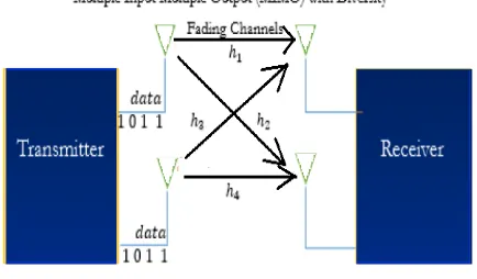
[image:2.595.319.536.314.441.2]Multiple-input and multiple-output (MIMO) is actually the concept of using multiple antennas at the transmitter as well as the receiver thereby multiplying transmitting and receiving capacity. The idea behind using multiple antennas is influenced by the fact that different antennas furnish different signal paths through the space independent to each other.
Figure 1: MIMO system
As a result, the data rate is increased up to N (bits/s)/Hz for N transmitting and receiving antennas. So, it can be concluded that integration of more antennas operating in the same frequency increases the information rate in a linear fashion without any increase in power..
Figure 2: MIMO increasesinformation rate without increasing power
[image:2.595.338.513.542.656.2]Retrieval Number: B10751292S19/2019©BEIESP
[image:3.595.81.255.128.238.2]the space thereby incorporating reliability of the system and range extension. Reliability is dependent on the fact that all the duplicate data signals travelling along different paths may not encounter same level of fading. Use of multiple antennas also increases the range as at the receiver end high amount of signal is accumulated.
Figure 3: Spatial diversity and multiplexing concept of MIMO
On the other hand, in case of spatial multiplexing, separate paths through the space carry separate independent data signals in parallel between the transmitter and the receiver. Performance of the system incorporating spatial multiplexing depends on construction and decoding process.
If NTis the number of antennas in the transmitter
and NR is the number of antennas in the receiver then the
input/output relation of the MIMO channel is described as below.
(1)
In other way, it can be expressed as Y=HX+N (2) Here Y is the vector representing received signal, H represents the channel matrix, X is the vector representing transmitted signal and N is the vector denoting the noise. For the purpose of determining the capacity of MIMO channel, at the transmitter as well as the receiver side, the MIMO channel is to be converted to N = min(NT,NR) SISO
(single input and single output) channels by following linear transformation. Then the capacity of MIMO channel can be defines as
C = log2 [det(IM+ SNR/NTHHH)] (3)
Here H denotes channel impulse response, HH indicated the conjugate of transpose corresponding to H, IM denotes
identity matrix of dimension NT×MR. It can be concluded
that in case of MIMO, capacity grows faster than SISO and SIMO (single input multiple output).
When an antenna can switch between different frequency bands and radiation patterns in dynamic manner, then that antenna is termed as reconfigurable antenna.
Mechanisms like switches, capacitors make changes in the antenna properties by applying radio frequency current through the antennas in forceful dissemination manner. MIMO can be implemented as reconfigurable antennas where in varying frequencies and polarization different radiation pattern can be achieved.
Microstrip patch antenna
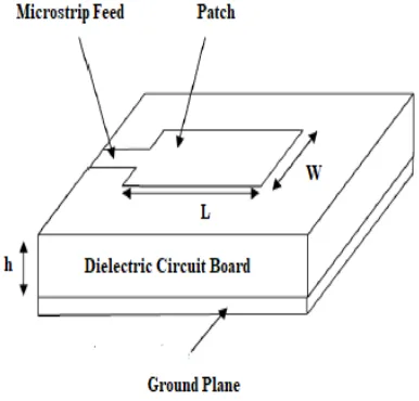
Microstrip patch antenna in these days is becoming extensively useful as they are of low weight, height, width and easily assembled on a circuit board. The general structure of microstrip patch antenna has been depicted in the figure below.
Figure 4: Microstrip patch antenna
The diagram above shows a microstrip patch antenna along with a transmission line feed. In general, a high conductive metal like copper is used for the patch, transmission line and the ground plane. L and W denote the length and width of the patch antenna and height of the dielectric circuit board is denoted by h.
A patch antenna can be of different shapes printed on a circuit board with a ground plane on the opposite side of the patch operating in microwave frequencies. An array of patch antenna is composed of many patches arranged in 2D array. The antenna patches are attached to the transmitter and the receiver via the transmission lines. For generating transmitting and receiving signals current is passed between patch and the ground plane. The value of h should be significantly less than the operation wavelength but not less than 1/40th of the wavelength.
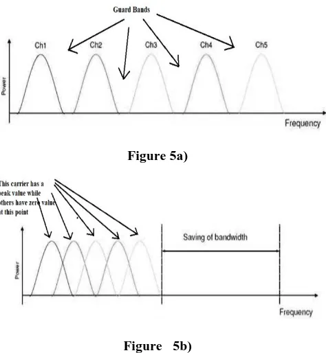
Orthogonal Frequency Division Multiplexing (OFDM) OFDM extends the capability of FDM (Frequency Division Multiplexing) by using the concept of orthogonality. In FDM, the large bandwidth of the transmission medium is partitioned into a sequence of small frequency ranges separated by a narrow frequency range known as guard band for avoiding interference due to overlapping. Different data signals ob different sub-carriers
[image:3.595.333.526.233.418.2]Figure 5a)
Figure 5b)
Figure 5: Bandwidths utilization in a) FDM and b) OFDM
[image:4.595.54.291.70.327.2]OFDM also partitions the channel bandwidth into different sub-channels with narrow frequency range. But instead of using guard bands like FDM, the sub-channels are overlapped here. The concept of orthogonality is used to avoid interference between overlapped sub-channels. The concept of orthogonality of the sub-carriers refers to the independence of the sub-carriers. The independence is affected by making only one carrier having non-zero value and all the others having zero value with respect to sampling points in the frequency domain. A diagram of a basic OFDM system has been illustrated below.
Figure 6: A basic OFDM system
The digital modulation schemes like QPSK, 16 QAM and so on are aided for performing the modulation of the sub-carriers. Suitable modulation and demodulation by the aid of Inverse Fast Fourier Transform (IFFT) at the sending end and Fast Fourier Transform (FFT) at the receiver end has been made possible by the concept of orthogonality. For error detection and correction in the received data, forward error correction mechanism is used.
High information rate and strong interference mechanism attributes have made OFDM so popular that it is the most primary technique for wireless LAN applications.
MIMO-OFDM
The advantageous properties like fast speed and less corrupted data delivery achieved by OFDM by the aid of partitioning of available radio bandwidth into different sub-channels can be effectively used by MIMO antennas by carrying different data signals transmitted by different antennas through the different sub-channels. The most fundamental concept behind the success of OFDM is orthogonality which is maintained in the MIMO system by keeping the transmitted signals from different antennas orthogonal to each other with the aid of space time coding. OFDM on the other hand, removes the possibility of interference, the most significant barrier of wireless communication.
By using FFT in OFDM a complex signal is segmented into simple sine waves. Also the bandwidth is effectively used by FFT by keeping time domain signals orthogonal to each other. As MIMO makes effective use of multipath propagation, a problem in wireless communication and OFDM does not carry out equalization of signals, combination of MIMO and OFDM can be very much appropriate for high speed demanding wireless communication. Irrespective of the availability of the information regarding channel state, the information rate achievable by the MIMO-OFDM is very high.
III. RESULT AND DISCUSSION
[image:4.595.317.538.499.614.2]In this work, the radiation efficiency of 2×2 MIMO microstrip reconfigurable antenna for two different dielectric constant and varying substrate height has been analyzed. The simulation has been performed in MATLAB R2016a environment.
Figure 7: MATLAB R2016a simulation environment Experiment 1: Effect of “SNR per bit” on BER W.R.T. QAM modulation
[image:4.595.76.257.514.629.2]Retrieval Number: B10751292S19/2019©BEIESP
(Eb/N0), also known as normalized SNR or SNR per bit.
With each data bit, the energy of the signal is denoted as Eb
measured by dividing the signal power by the bit rate. N0
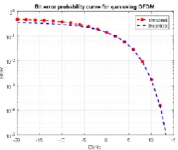
denotes spectral density of the noise. The following graph depicts Eb/N0 vs bit error rate (BER) relation for QAM
[image:5.595.335.505.50.626.2]modulation technique with respect to the current MIMO-OFDM system.
Figure 8: Bit error probability curve for QAM using OFDM
From the above graph it can be concluded that as SNR per bit increases, the BER decreases in MIMO-OFDM system. For the ratio of Eb/N0 greater than 5, BER decreases
significantly. Also, the simulation result matches with the theoretical limit.
[image:5.595.104.231.141.248.2]Experiment 2: Effect of varying substrate height on radiation efficiency W.R.T. dielectric constant 3.3 In this experiment dielectric constant has been considered is 3.3. Then for different substrate height, the radiation efficiency of the patch antenna at 2.4 GHz has been analyzed. The table shown below illustrates the percentage efficiency of patch antenna radiation for different substrate height from 0.0001 mm to 0.0020 mm. Radiation efficiency is expressed in percentage and operating frequency is expressed in GHz.
Table 1: Radiation efficiency at different substrate heights with dielectric constant 3.3
Length Efficiency
0.1e-3 99.45
0.2e-3 98.91
0.5e-3 97.29
1.5e-3 92.03
2.0e-3 89.49
The charts below depict the radiation efficiency of the patch antenna for different substrate heights at 2.4 GHz band with value of dielectric constant 3.3.
a)
b)
c)
d)
e)
Figure 9: Radiation efficiency at 2.4 GHz with dielectric constant 3.3 and for substrate heights a) .0001 mm b) .0002 mm c) .0005 mm d) .0015 mm e) .0020 mm
[image:5.595.79.251.642.770.2]patch antenna maintains good radiation efficiency at 2.4 GHz.
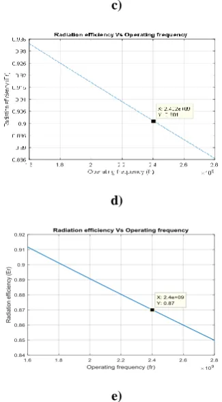
[image:6.595.341.504.53.347.2]Experiment 3: Effect of varying substrate height on radiation efficiency W.R.T. dielectric constant 4.4 In this experiment dielectric constant has been considered is 3.3. Then for different substrate height, the radiation efficiency of the patch antenna at 2.4 GHz has been analyzed. The table shown below illustrates the percentage efficiency of patch antenna radiation for different substrate height.
Table 2: Radiation efficiency at different substrate heights With dielectric constant 4.4.
Length Efficiency
0.1e-3 99.31
0.2e-3 98.63
0.5e-3 96.60
1.5e-3 90.10
2.0e-3 87.00
The charts below depict the radiation efficiency of the patch antenna for different substrate heights at 2.4 GHz band with value of dielectric constant 4.4.
a)
b)
c)
d)
e)
Figure 10: Radiation efficiency at 2.4 GHz with dielectric constant 3.3 and for substrate heights a) .0001 mm b)
.0002 mm c) .0005 mm d) .0015 mm e) .0020 mm It can observed from the above graphs that radiation efficiency percentages of the 2×2 MIMO patch antenna decreases steadily as the substrate height is increased from .0001 mm to .0025 mm at 2.4 GHz. The radiation efficiency percentage is 99%, highest at substrate height .0001mm and 83%, lowest at substrate height .0025 mm. Within the substrate height range 0.0001mm to 0.0025 mm, the MIMO patch antenna maintains good radiation efficiency at 2.4 GHz.
Experiment 4: Performance comparison of antennas having dielectric constant value 3.3 and 4.4
In this experiment, the radiation performance efficiencies corresponding to dielectric constant 3.3 and 4.4 has been compared. The following graph shows the radiation percentages of the two dielectric constant values 3.3 and 4.4 with respect to different substrate heights.
80 82 84 86 88 90 92 94 96 98 100 102
0.0001 0.0002 0.0005 0.001 0.0012 0.0014 0.0015 0.002 Substrate Heights
[image:6.595.85.242.396.783.2]Efficiency 3.3 Efficiency 4.4
[image:6.595.308.544.593.712.2]Retrieval Number: B10751292S19/2019©BEIESP
From the above graph, it can be observed that radiation performance of the antenna is better when the dielectric constant is taken as 3.3.
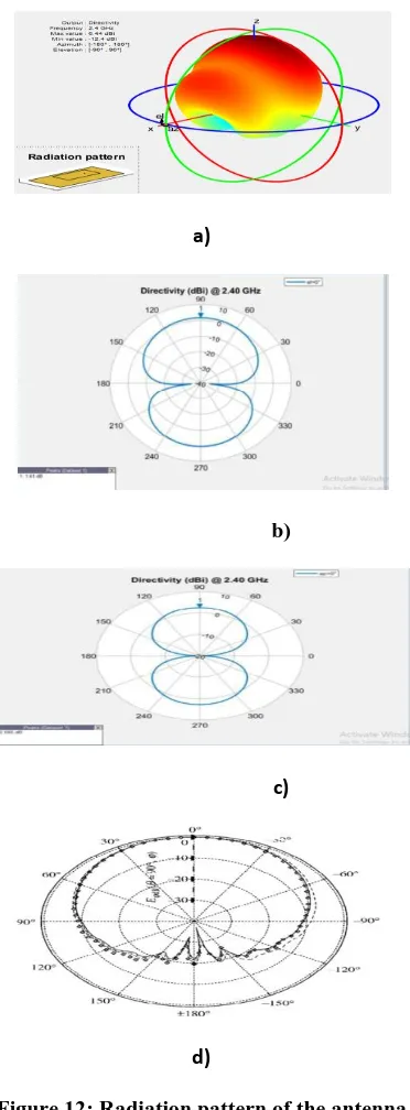
Experiment 5: Radiation pattern of Microstrip antenna Radiation pattern of an antenna refers to the strength of emission and reception in form of a wave pattern. The direction of the radiation of an antenna can be easily understood just by looking at the radiation pattern. The pattern of radiation is represented as a function of angular position and radiation distance from the antenna. The graphs below describe radiation pattern of the antenna.
a)
b)
c)
[image:7.595.342.516.175.253.2]d)
Figure 12: Radiation pattern of the antenna a) 3D radiation pattern b) azimuth cut c) elevation cut
d) 2D radiation pattern
From the above diagrams, it can be observed that the The radiation pattern of microstrip or patch antenna is broad. It
has low radiation power and narrow frequency bandwidth. In addition it has lesser directivity.
Experiment 6: Return loss analysis
[image:7.595.77.263.208.712.2]Return loss of an antenna refers to ratio of the portions of the rejected radio wave to the portions of the radio wave accepted. The unit of expressing return loss is decibel (dB). The following graph demonstrates the relation of return loss with frequency.
Figure 14: Return loss vs frequency for microstrip antenna
From the above graph it can be concluded that the return loss value decreases as frequency increases at 2.4 GHzand it has a low return loss value i.e. slightly greater tan 1 dB. That is approximately 20% of power reflects back to antenna.
IV. CONCLUSION
The dimension of a microstrip patch antenna has a great role in efficient transmission and reception of radio signals. High radiation efficiency of the antenna indicates effective power dissemination in the free space. Low radiation efficiency occurs due to properties of the metal conductor, dielectric as well as magnetic losses and others. These adverse effects should be minimized by providing high radiation efficient antenna for successful wireless communication. This research work has demonstrated that radiation efficiency of MIMO reconfigurable patch antenna for 2.4 GHz band is dependent on substrate height and the value of dielectric constant.
The experimental results indicate that as SNR per bit increases, the BER decreases in MIMO-OFDM system. The radiation efficiency percentages of the 2×2 MIMO patch antenna operating at 2.4 GHz decreases linearly as the substrate height is increased with dielectric constant value 3.3 and 4.4. It is also observed that the radiation pattern of Microstrip patch antenna is broad. It has low radiation power and narrow frequency bandwidth and the return loss value is decreases as frequency is increased. In addition, at 2.4 GHz the Microstrip patch antenna has a low return loss value.
REFERENCES
1. Abdullah Al-Mamun Bulbul, Sagor Biswas, Md. Bellal Hossain, Saibba Biswas, “Past, Present and Future of Mobile Wireless Communication”, IOSR Journal of Electronics and Communication Engineering (IOSR-JECE), Volume 12, Issue 5, Ver. I (Sep.- Oct. 2017), PP 55-58
2. “Mobile traffic Q1 2019”, Mobility report, Ericsson, June 2019 3. M. Shahwaiz Afaqui, Eduard Garcia-Villegas, Elena
Lopez-Aguilera, “IEEE 802.11ax: Challenges and requirements forfuture high efficiency Wi-Fi”, IEEE Wireless Communications, Vol. 24, Issue 3, pp. 130-137, 2016
4. “Wi-Fi”, Wikipedia, Source: https://en.wikipedia.org/wiki/Wi-Fi 5. Benkler, Y. (2011). Open Wireless vs. Licensed Spectrum:
Evidence from Market Adoption, pg. 1. Berkman Center for Internet and Society. Retrieved November 22, 2011, from http://cyber.law.harvard.edu/node/7211
6. N. Golmie, R.E. Van Dyck, A. Soltanian, A. Tonnerre and O. Rébala, “Interference Evaluation of Bluetooth and IEEE 802.11b Systems”, Wireless NetworksMay 2003, Volume 9, Issue 3, pp 201–211
7. Aayushi Mahajan, Swastik Gupta, “Interference Evaluation of Different Wireless Systems Operating in 2.4 GHz ISM Band”, NCVSComs-13 CONFERENCE PROCEEDINGS, pp. 65-68, 2013
8. David Gesbert, Mansoor Shafi, Da-shan Shiu,Peter J. Smith, and Ayman Naguib, “From Theory to Practice: An Overview of MIMOSpace–Time Coded Wireless Systems”, IEEE Journal on Selected Areas in Communications, Vol. 21, No. 3, pp. 281-302, 2003
9. Saba Qasim Jabbar and Yu Li, “Analysis and Evaluation of Performance Gains and
10. Tradeoffs for Massive MIMO Systems”, Applied Sciences, Vol. 6, Issue 10, 2016
11. Michel T. Ivrla, Josef A. Nossek, “MIMO Performance Gains – A Signal Processing Point of View”, Automation: Journal of Automation, Measurement, Electronics, Computing and Communications, Vol. 47, No. 1, pp. 97-104, 2006
12. H Elsadek,”Mobile and Wireless Communications Network Layer”,IntechOpen, Chapter 9, 2010
13. David Angell, “Next-Gen 802.11ac Wi-Fi for Dummies”, Intel Special Edition
14. Yongkang Liu, Nader Moayeri, “Wireless Activities in the 2 GHz Radio Bands in Industrial Plants”, NIST Technical Note, 1972 15. “2.4 GHz Radio use”, Wikipedia, Source:
https://en.wikipedia.org/wiki/2.4_GHz_radio_use
16. R. R. Deshmukh, V.B.Waghmare, “Bluetooth and Wi-Fi Coexistence Issues and Solutions (Review)”, National Conference on New Generation Wireless Communication Technologies by IEEE Communication Society, 2009
17. Salim Abukharis, Jafar A. Alzubi, Omar A. Alzubi and Saeed Alamri, “Packet Error Rate Performance of IEEE802.11g under Bluetooth Interface”, Research Journal of Applied Sciences, Engineering and Technology, Vol. 8, No. 12,pp. 1419-1423, 2014 18. N. Azmi et al, “Interference Issues and Mitigation Method in
WSN 2.4GHz ISM Band: A Survey”, International Conference on Electronic Design (ICED), pp. 403-408, IEEE, 2014
19. Wenqi Guo, William M. Healy, and MengChu Zhou, “Impacts of 2.4-GHz ISM Band Interference onIEEE 802.15.4 Wireless Sensor NetworkReliability in Buildings”, IEEE Transactions On Instrumentation and Measurement, Vol. 61, No. 9, pp. 2533-2544, 2012
20. A.S. Oluwole & V. M. Srivastava, “Smart Antenna at 300 MHz for Wireless Communications”, African Journal of Computing & ICT, Vol 8. No. 3 Issue 2, pp. 193-201, 2015
21. T. S. Ghouse Basha, M. N. Giri Prasad, P. V. Sridevi, “Beam forming in smart antenna with improved gainand suppressed interference using genetic algorithm”, Central European Journal of Computer Science, Vol. 2, No. 1, pp. 1-14, 2012
22. Asad Ali Siddiqui et al, “Interference mitigation in 4G system using Smart Antenna”, International Conference on Information and Communication Technologies, 2011
23. Ayushi Agarwal, Amanpreet Kaur, “A Review Paper on Stacked MicrostripAntenna for MIMO Application”, International Journal of Electricals and Electronics Engineering, Vol. 2, Spl. Issue 2, pp. 232-235, 2015
24. Celal Alp Tunc, Ugur Olgun,Vakur B. Erturk, and Ayhan Altintas, “On the Capacity of Printed Planar Rectangular Patch Antenna Arrays in theMIMO Channel:Analysis and Measurements”, IEEE
Antennas and Propagation Magazine, Vol. 52, No. 6, pp. 181-193, 20 10
25. A.B. MUTIARA, R.REFIANTI, RACHMANSYAH, “Design Of Microstrip Antenna For Wireless Communication At 2.4 Ghz”, Journal of Theoretical and Applied Information Technology, Vol. 33, No. 2, pp. 184-192, 2011
26. P.A. Nawale, Prof. R.G. Zope, “Rectangular Microstrip Patch Antenna for 2.4 GHz Communication Using Defected Ground Structure”, International Journal of Advance Foundation and Research in Computer (IJAFRC), Vol. 2, Issue 1, pp. 1-14, 2015
AUTHORS PROFILE
Sandeepkumar kulkarni received his Bachelor Degree in Electronics and Instrumentation from Gulbarga University, Gulbarga and Master Degree in Power Electronics from VTU –Belgaum in 2001 and 2006 respectively. In 2013, he joined in VTU-Belgaum as Ph.D part time student in MIMO microstrip antenna group and carrying his research work under the direction of Dr. Raju Yanamshetti, PDACE-Gulbarga. He has Membership of IEI, KRVP and KSP. Guided several UG and PG students and presented papers in National, International and UGC approved journals.