International Journal of Innovative Technology and Exploring Engineering (IJITEE) ISSN: 2278-3075, Volume-8 Issue-12, October 2019
Abstract: Energy efficiency of Induction motor (IM) is essential in the current scenario due to the reasons such as energy conservation and economic saving. In this project, the implementation of the safe speed control of IM is done. The Programmable Logic Controller (PLC) monitors the speed and trips the motor under safety requirements. PLC is used to control three phase IM with the Variable Frequency Drive (VFD). The availability of drive data and software helps to manipulate and analyze process the information. The Human Machine Interface (HMI) is used for the visual monitoring and control of the induction motor. The PLC based control platform makes system to be communicated to other devices on network and makes the system more flexible for its operation and control. The results shows that, the speed of the induction motor varies linearly with the change in frequency in HMI and the motor trips if there is any human interference within 10 cm operating range of IM.
Keywords : Human Machine Interface (HMI), Induction motor (IM), Programmable Logic Controller (PLC ) Speed Control, Variable Frequency Drive (VFD).
I. INTRODUCTION
Nowadays the main research focus in Electrical Engineering is to improve energy efficiency and to explore new effective and more intelligent ways to utilize electricity. The awareness of concept of energy conservation is required to save electricity for the future generation. Even the energy saving of 0.01% yields lots of benefit to the nation. Electric motors are industries basic need. Industries consume about 50% of the power generated in the country and electric motors consume about 72% of the total electricity used in the industrial power. Three phase IMs are the prime source of energy consumption in industry.
Industrial applications such as elevators, cranes, lathes, drilling machine, blower, fans, pumps, etc. are actuated by induction motors due to their reliability, low cost, robustness and easy maintenance. The speed control of motor with human machine interface results in high performance variable-speed applications. In number of industries, motors must satisfy very strict speed requirements, both with respect
Revised Manuscript Received on October 05, 2019. * Correspondence Author
S. J. Suji Prasad*, Department of Electronics and Instrumentation
Engineering, Kongu Engineering College, Erode, Tamil Nadu, India. Email: [email protected]
R. Suganeh, Department of Electronics and Instrumentation
Engineering, Kongu Engineering College, Erode, Tamil Nadu, India. Email: [email protected]
R. Suresh kumar, Department of Electronics and Instrumentation
Engineering, Kongu Engineering College, Erode, Tamil Nadu, India. Email: [email protected]
to the range and smoothness of control as well as economical operation.
However, IMs take reactive power from the supply system to setup its working air gap flux causing the IM to always operate at lagging power factor (pf). Hence, organizations having a large number of IMs cause huge transfer of reactive power from the utility to the network grid. This results in an increase in the network losses and reduction in the voltage level leading to poor reliability, safety problems and higher energy costs.
On line condition monitoring of electrical machines has become n area of growing interest and importance. It relies on the graphical trend of the machine parameters for detecting machine problems before the failure takes place. Because of the key role that IMs play in many industrial processes, the prevention of machine failures causing unplanned production shutdowns can significantly increase profits.
The use of the VFDs for the starting of the induction motor reduces the high inrush current, thus preventing the sag developing the distribution lines. The speed control is also easily achieved by using the VFD. Combining these drives with PLC control can result in great energy efficiency, which can in turn have impact o global warming. The technology advancement and availability of electric drives, the automation systems in manufacturing units are introduced with PLC.
The automation processes with the use of PLC increases reliability and flexibility and also reduces production costs. Power converters, personal computers and other electric equipments are interfaced with PLC to obtain accurate industrial electric drive systems.. By the use of the PLC and Human Machine Interface (HMI) system entire system can be monitored.
II. LITERATURE REVIEW
Muawia et al. (2015) used the VFD for controlling the speed of the induction motor. The author stated that the drawback of the Field oriented control is overcome by using Hybrid Fuzzy-Fuzzy Controller. The controller is analyzed and found that the controller is an efficient, reliable one which is robust to control load and noise disturbances.
Jain et al. (2016) used the PLC for the power factor correction of the three-phase induction motors. The three-phase induction motor has a low power factor (pf) at no load as it draws large magnetizing current and the active power delivered to the motor is low, which is utilized to overcome the no-load losses. Based on the
measured pf value, the PLC switches the approximate
Safe operation of Induction Motor with
Programmable Logic Controller and Human
Machine Interface
capacitor banks into the circuit to improve pf. large scale use of PLC in industrial automation, adaptability, simple implementation and economics justified its selection as the switching controller. Use of PLC as a PFC has proved to be a versatile, efficient and cost-effective tool for an industrial application, especially for organizations employing a large number of IMs. This results in the improvement of the power quality and substantial saving in energy cost and conservation of energy.
Sánchez et al. (2013) developed an open, multilevel condition monitoring system for IMs. The parameters of the IM are measured with commercial, industrial equipment transmitted to a PLC. An OPC client-server with SCADA program is used to display the motor status, and it stores the data perform trend analysis. The use of open specifications for data communications and PLC software development has allowed the construction of the proposed system using industrial, commercially available components, instead of requiring custom-developed equipment. This approach also facilitates its integration into information networks at the enterprise level.
Bocker (2007) briefly explained various control schemes for the induction motor. He discussed the control aspects of IM drives and sensorless control of the IMs. Also, he discussed the industrial standards for the IM. The FOC is a Feed-forward control by calculating the slip frequency from the reference values. The Direct Self Control (DSC) and Direct Torque Control (DTC) govern the stator flux employing hysteresis control. The difference is that DSC performs hexagonal flux trajectory and DTC is circular. Both possess high torque dynamics compared to FOC. Both techniques have variable switching frequency and higher torque ripple. The sensorless speed control is used because of reduced cost.
Rinchen Geongmit Dorjee et al. (2014) presented the model for the monitoring and control of VFD using PLC and SCADA. VFD was controlled using SCADA integrated PLC system. The human operator also cans monitor the entire process with HMI.
Sagar P.Jain and Sanjay L.Haridas have put forward VFD for conveyor assembly in an automated bottling plant. The MicroLogix 1400 PLC is used with RSLOGIX 500 and RS LINX 500 for programming and communication.
S.Takiyarand B.K.Chauhan (2013) delineated paper on Hybrid method for customized control of Induction Motor using PLC. This system featured and adaptive control for flexible operation. This control system has the ability to evolve its control strategy for flexible operations continuously. The comparison of speed torque performance and efficiency of PLC based and inverter-based VFD were presented.
R. CharletPriya (2014) has simulated the design of VFD Induction Motor using seven-level inverters developed from modified H-bridge in air conditioners for power reduction. The use of VFD in the AC will reduce the high in-rush current which makes the AC consume more power and facilitates constant power consumption. The unipolar or bipolar output voltage switching is provided by the inverter to provide in seven different switching states. PROTEUS SIMULINK software is used for the simulation.
Ankur P. Desai et al. (2014) illustrated the energy conservation using variable frequency drive in pumping application. Torque speed characteristics of VFD were
analyzed with different operating modes. The comparison analysis of pumping operation with and without VFD is shown in the paper.
Thavatchai Tayjasanant et al. (2005) presented that in Inter harmonic- Flicker curves by a limit for inter harmonics is being proposed in this paper by considering the published limits for voltage flicker. Flicker Curve is the curve of inter harmonic magnitude versus inter harmonic frequency. Enhancement is to be done with IEC flicker meter when it dealt with harmonic caused flickers. The VFDs typically produce pair of inter harmonic currents with the same magnitude. These currents will interact with the system impedance, resulting in two inter harmonic voltages of different magnitudes. The relationship between inter harmonic and flicker is determined. Generation of inter harmonics from Current Source Inverter (CSI) VFD is demonstrated and illustrated with an example for precise understanding.
Sanjay N. Huse et al. (2015) have presented a case study for the water supply system to buildings. The main concerns such as throttling were considered while designing VFD for the system. The throttling effect can be minimized, and the extra power consumption can be saved by the application of the VFD as shown in the paper. The use of the VFD drive provides significant savings in both cost and GHG emissions. The flowchart for the automatic control of motor pumps is also shown in the paper.
Robert A. Hanna (1989), discussed the harmonics that are generated in the VFDs. Various source of current and voltage harmonics and their effects are discussed. The presence and analysis of harmonics are explained with the help of a few cases. The author concludes that the order and magnitudes of the harmonics generated are dependent on drive configuration and system impedance.
Vaibhav Gupta (2018) demonstrated the induction motor speed control using PLC and SCADA in his study. The measured speed using a tachometer is fed it the PLC. PLC takes action based on the desired input, and then the signal is transferred to the motor via driver to increase / decrease the speed. In this study, the control system will be held using the available Siemens PLC.
In IM the controlling of speed is not an easy task. Various types of starters are used for the starting of the IMs. But due to low cost the DOL starter is widely used. The DOL starter is cheap and easy to operate but it has the major disadvantage that during motor starting high inrush current is drawn from the supply line which will affect the electronic devices connected to the supply line. In order to avoid this need of the soft starters are increasing.
International Journal of Innovative Technology and Exploring Engineering (IJITEE) ISSN: 2278-3075, Volume-8 Issue-12, October 2019
III. METHODOLOGY
[image:3.595.324.527.47.395.2]The block diagram of Induction Motor Speed Control Using PLC and HMI is shown in figure 1.
Figure 1. Induction Motor Speed Control Using PLC and HMI
The above block diagram shows the control system to control the speed of a 3-phase induction motor. The proposed system consists of Power Supply, SMPS, PLC, HMI, VFD, IM, Proximity Sensor and Photoconductive Switch. The 230V AC supply is taken from the mains and given to the VFD and the SMPS. The 24V DC supply is given to all the equipments other than the IM. The output of the VFD is 440V AC supply which is fed to the IM.
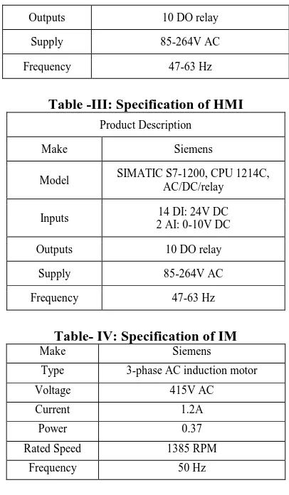
[image:3.595.60.280.102.217.2]In the taken project the PLC used is Siemens S7-1200 1214 AC/DC/RLY which has 14 Digital inputs and 10 Digital output each of 24VDC and two analog inputs (0-10) V. The VFD is Siemens Sinamics V20 which converts 230V single phase supply to 3-phase 440V supply. The HMI is Siemens KTP 700 Basic which has 8 Screens. Specifications of equipments used are presented in tables 1, 2, 3 and 4.
Table-I: Specifications of VFD Power
Input Voltage 1Ф 230V AC
Output
Voltage 3Ф 400V AC
Power Factor ≥0.95/0.72
Supply
Frequency 50/60 Hz
Overload
Current 150% of rated current
Signal Inputs and Outputs
Analog input
AI1: Bipolar Current/Voltage AI2: Unipolar Current/Voltage
Can be used as digital inputs
Analog
output AO1: 0-20mA
Digital inputs DI-DI4, optically isolated PNP/NPN
selectable by terminal
Table -II: Specification of PLC Product Description
Make Siemens
Model SIMATIC S7-1200, CPU 1214C,
AC/DC/relay
Inputs 14 DI: 24V DC
2 AI: 0-10V DC
Outputs 10 DO relay
Supply 85-264V AC
Frequency 47-63 Hz
Table -III: Specification of HMI Product Description
Make Siemens
Model SIMATIC S7-1200, CPU 1214C,
AC/DC/relay
Inputs 14 DI: 24V DC
2 AI: 0-10V DC
Outputs 10 DO relay
Supply 85-264V AC
Frequency 47-63 Hz
Table- IV: Specification of IM
Make Siemens
Type 3-phase AC induction motor
Voltage 415V AC
Current 1.2A
Power 0.37
Rated Speed 1385 RPM
Frequency 50 Hz
IV. RESULTANDDISCUSSION
The control system is designed to run the motor in the desired speed. The PLC is the controller which is used to control the speed of the IM. By the use of the PLC the motor is made to run in both forward and reverse direction. By varying the analog output (0- 10V) from the PLC, the frequency of the VFD can be changed. The speed of the induction is measured by using the proximity sensor. The output of the proximity sensor is given to the PLC. There is an inbuilt high-speed counter present in the PLC.
The Photoelectric switch is used to detect any interference near the induction motor. If there is any interference, the output of the photoelectric switch goes high, and the system will stop. The connection diagram between PLC and VFD is shown in figure 2.
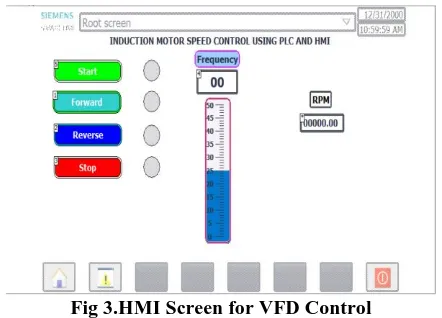
[image:3.595.65.273.429.786.2]From the figure2, it is observed that the 230VAC supply is given to the PLC from the SMPS. The output of the photoelectric switch is given to the pin I0.0, and the output from PLC Q0.0 is given to pin DI 1 of the VFD and the output Q0.1 is given to DI 2 of the VFD. The analog output from the VFD A0 is given to AI 1 of the VFD. The human machine interface is shown in figure 3.
Fig 3.HMI Screen for VFD Control
[image:4.595.58.279.142.301.2]From the figure3, it is seen that there are touch screen controls for the operations and mode selection. The monitoring f the speed and safety interlock is also displayed in the HMI screen. The hardware interface is shown in figure 4.
Fig 3. Hardware Setup for Induction Motor speed control using PLC and HMI
The figure 4 depicts the induction motor speed control with the Siemens PLC and HMI. The observations are tabulated in table 5.
Table-V: Performance of IM with VFD S.
No
Freque ncy (Hz)
Analog Output Voltage
from PLC
(VDC)
3-phase output Voltage from VFD (VAC)
Speed
of the
Motor (RPM)
1 0 0 28 0
2 2 0.39 59 58.4
3 4 0.79 76 118
4 5 0.99 89 150
5 8 1.58 110 240
6 10 1.98 123 300
7 15 2.97 163 450
8 20 3.97 195 600
9 25 4.96 234 754
10 30 5.95 244 923
11 35 6.95 245 1056
12 40 7.94 246 1204
13 45 8.93 246 1362
14 50 9.93 246 1502
From the above table, it is observed that as the input frequency to the PLC increases, the PLC output analog voltage is increased linearly. The analog output is given to the VFD analog input channel. Therefore, the increase in the analog voltage increases the 3-phase line to line output voltage which is given to the motor. The increase in the 3-phase voltage increases the speed of the motor.
V. CONCLUSION
In this paper, the design of VFD hardware system for changing the speed of the motor by changing the output frequency is presented. Finally, it is concluded that the method of speed control of three-phase induction motor using variable frequency drive is the effective and efficient method, when the operation of VFD is done by PLC. The whole system gives the operation to a level of accuracy, ability and totally with maximum safety. It is possible that, the speed control system can be implemented to control multiple motors with the same drive and programmable logic controller, the PLC system which is used in this paper also used for monitoring and controlling the other parameter of the motor with the same drive. The results show that, the speed of the induction motor varies linearly with the change in frequency in HMI and the motor trips if there is any human interference within 10 cm operating range of IM. In future the IM can be connected to various types of loads and a feedback loop control system can be implemented.
REFERENCES
1 Ankur P. Desai, Rakesh.J.Motiyani, Ajitsinh R.Chudasama, “Energy Conservation Using Variable Frequency Drive in Pumping Application”, Proceedings of International Journal of Engineering Development and Research, 2014, pp 121-126.
2 Birbir, Y. and H.S. Nogay, Design and implementation of PLC-based monitoring control system for three-phase induction motors fed by PWM inverter. International journal of systems applications, engineering & development, 2008. 2(3): p. 128-135.
3 Gupta, V., Induction Motor Speed Control Using PLC AND SCADA. International Research Journal of Engineering and Technology, 2018. Vol. 05 no. 03.
4 KM, M.K. and B. Ramachandra, Speed Control of Three Phase Induction Motor Using PLC under Open and Closed Loop Condition. International Journal of Engineering Research and Applications, 2017. Vol. 07 no.01, p. 34-39.
5 R. CharletPriya, “Variable Frequency Drive Induction Motor in Air Conditioner Using Seven-Level Inverter”, International Journal of Advanced Research in Electrical, Electronics and Instrumentation Engineering, 2014, Vol. 3, Special Issue 4, pp-12-19.
6 Rinchen Geongmit Dorjee. “Monitoring and Control of a Variable Frequency Drive Using PLC and SCADA”, International Journal on Recent and Innovation Trends in Computing and Communication, 2014, Vol. 02, no.10, pp-3092-3098.
7 Robert A. Hanna, “Harmonics and technical barriers in Adjustable Speed Drives”, IEEE Transactions on Industry Applications,1989, Vol. 25, no. 5, pp. 894-900.
8 S Takiyar and B. K. Chauhan, “Hybrid Method for Customized Control of Induction Motor”, International Journal of Computer and Electrical Engineering, 2013, Vol. 5, no. 4, pp.350-355.
9 S. Sneha, S. Radhika,"Controlling and Protection of Three Phase Induction Motor Using PLC", International Journal for Research in Applied Science and Engineering
[image:4.595.61.287.357.553.2]International Journal of Innovative Technology and Exploring Engineering (IJITEE) ISSN: 2278-3075, Volume-8 Issue-12, October 2019
10 Sagar P. Jain and Sanjay L. Haridas, “Energy Efficient Automized Bottling Plant Using PLC and SCADA With Speed Variable Conveyor Assembly”, IOSR Journal of Electronics and Communication Engineering, 2014, vol. 9, no 1, PP 09-14.
11 Sanjay N. Huse, Ravindra D. Kale, D.R.Mane, V.P.Dhote, “Use of the VFD to minimize the throttling effect of the Hostel water supply system by the automation of the system”, International Journal of Scientific & Engineering Research,2015, Vol. 6, no 2, pp-92-96. 12 Sowmiya, D. Monitoring and control of a PLC based VFD fed three
phase induction motor for powder compacting press machine. in 2013 7th International Conference on Intelligent Systems and Control (ISCO). 2013.
13 Thavatchai Tayjasanant, Wilsun Xu, “Interharmonic-Flicker Curves”, IEEE Transactions on Power Delivery, 2005, Vol. 20, No. 2, pp-1017-1024.
AUTHORSPROFILE
S. J. Suji Prasad is working as Associate Professor in the department of Electronics and Instrumentation Engineering at Kongu Engineering College. His research interests focus on Process modeling, Controller design and Process control. He has 36 publications in International journals and 0conferences on his credit.
R.Suganesh has completed his bachelor’s degree in Electrical and Electronics Engineering from Panimalar Engineering College, Chennai. He is currently pursuing his master’s degree in Control and Instrumentation Engineering in Kongu Engineering College, Perundurai.