A STUDY ON EFFECT OF PROCESS PARAMETERS IN SHEET METAL FORMING SIMULATION OF AA5052
TEE SHAW TING
A report submitted
in fulfillment of the requirements for the degree of Bachelor of Mechanical Engineering (Structure & Materials)
Faculty of Mechanical Engineering
UNIVERSITI TEKNIKAL MALAYSIA MELAKA
ii
DECLARATION
I declare that this project report entitled “A Study on Effect of Process Parameters In Sheet Metal Forming Simulation of AA5052” is the result of my own work except as cited in the references.
Signature : ... Name : Tee Shaw Ting
iii APPROVAL
I hereby declare that I have read this project report and in my opinion this report is sufficient in terms of scope and quality for the award of the degree of Bachelor of Mechanical Engineering (Structure & Materials).
iv
DEDICATION
v
ABSTRACT
vi
ABSTRAK
Proses pembentukan merupakan satu proses yang amat penting di industri
pembuatan. Kajian ini dijalankan untuk mempelajari implikasi proses parameter AA
5052-O dalam proses pembentukan. Kajian ini dijalankan dengan menggunakan
cara simulasi. Perisian LS DYNA 9.71 telah digunakan untuk mensimulasikan
seluruh proses. Pengesahan keputusan simulasi telah berjaya dengan
membandingkan dengan keputusan eksperimen dalam situasi yang sama. Perbaikan
mesh, pekali geseran, dan maklumat bahan merupakan khuatir yang penting dalam
pengesahan keputusan simulasi. Hasil eksperimen menunjukkan kepingan logam AA
5052-O dengan ketebalan 1.5mm adalah lebih sesuai dalam proses pembentukan.
vii
ACKNOWLEDGEMENT
I would like to express my sincere thanks to my supervisor Dr. Sivakumar A/L Dhar Malingam for giving me this opportunity to do final year project with him. He helped me to catch up many new issues in finite element analysis which was a new field of study for me.
I also would like to especially thank my senior named Rosmia and Ng Lin Feng for all their guidance especially in obtaining experiment work and fruitful discussions.
viii CONTENT
CHAPTER CONTENT PAGE
DECLARATION APPROVAL DEDICATION ABSTRACT ABSTRAK ACKNOWLEDGEMENT ii iii iv v vi vii
TABLE OF CONTENT viii
LIST OF FIGURES x
LIST OF TABLES xiii
LIST OF ABBREVIATIONS xiv
CHAPTER 1 INTRODUCTION 1
1.1 Background of Study 1
1.2 Problem Statement 4
1.3 Objective 4
1.4 Scope Of Project 5
CHAPTER 2 LITERATURE REVIEW 6
2.1 Introduction 6
2.2 Metal Forming 6
2.2.1 Sheet Metal Forming Defects 12 2.3 Process Parameter in Sheet Metal Forming 16 2.3.1 Effect of Blank Holder Force 18
2.3.2 Effect of Punch Velocity 19
2.3.3 Effect of Thickness of Blank 21
2.4 Finite Element Method 22
2.4.1 FEA method in stamp forming 25
ix
CHAPTER 3 METHODOLOGY 27
3.1 Introduction 27
3.2 Model Design 29
3.3 Simulation 30
3.3.1 Properties of Parts 3.3.2 Interaction
3.3.3 Meshing of FE model 3.3.4 Process Parameter 3.3.5 Data and Result
30 31 32 33 34
3.5 Result Analysis 35
CHAPTER 4 RESULTS AND DISCUSSION 36
4.1 Introduction 36
4.2 Validation of model 36
4.2.1 Mesh refinement 4.2.2 Interaction
4.2.3 Material model 4.2.4 Material Properties
38 41 43 45
4.3 Effect of blank thickness 48
4.4 Effect of blank holder force 54
4.5 Effect of punch velocity 55
CHAPTER 5 CONCLUSION AND RECOMMENDATION 62
5.1 Conclusion 62
5.1 Recommendation 63
x
LIST OF FIGURES
FIGURE TITLE PAGE
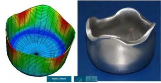
1.1 Sheet forming in finite element simulation and empirical method
3
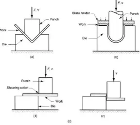
2.1 Sheet metal working (a) Bending; (b) Drawing; (c) Shearing; (1) as punch first contact sheet and (2) after cutting
8
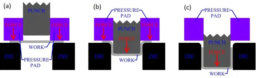
2.2 Figure 2.2: Simple Deep Drawing Process (a) Initial position of tools; (b) Punch moving down to deform the work; (c) The work is fully deformed
9
2.3 Yield locus for plane stress for Tresca and Von Mises 12
2.4 Defects in deep drawn cylindrical cup. (a) Flange wrinkling. (b) Wall wrinkling. (c) Tearing. (d) Earing. (e) Surface scratches
13
2.5 Uncertainty and variation sources in the sheet metal forming process
17
3.1 Flow chart of the methodology 28
3.2 Schematic diagram of tools set in millimeter 29
3.3 Isometric view of model design 30
3.4 Meshing of model 33
4.1 Force displacement graph in experiment 37
4.2 Model optimization process 38
xi
LIST OF FIGURES
FIGURE TITLE PAGE
4.4 Graph of maximum reaction force versus number of elements 40
4.5 Result of variation of coefficient of friction 42
4.6 0.5 dynamic coefficients of friction with variation of static coefficient of friction
43
4.7 Graph of force displacement from different material card 45
4.8 Graph of comparison with varies strength coefficient and hardening exponent
47
4.9 The best fits curve between experimental and simulation 47
4.10 Thickness location for the drawn cup in simulation model 49
4.11 Distribution of sheet metal thickness with variation of blank thickness
50
4.12 Comparative graphical result with variation of the blank thickness where (a) Thickness reduction; (b) Displacement
51
4.13 Effect of the relative punch diameter on limiting drawing ratio 52
4.14 Comparative graphical result with variation of punch velocity where (a) Stress; (b) Plastic strain; (c) Thickness reduction; (d) Displacement
56
xii
LIST OF FIGURES
FIGURE TITLE PAGE
4.16 Thickness contour with variation of punch velocity (a) 8.33 mm/s; (b) 100 mm/s; (c) 200mm/s
59
4.17 Curve between punch force and punch progression with variation punch velocity
60
xiii
LIST OF TABLES
TABLE TITLE PAGE
3.1 Material properties of Aluminum 5052 from Metals Handbook, Vol.2 and tensile test conducted
31
3.2 Process parameter value considered 34
4.1 Parameters in forming test 37
4.2 Number of element and respective maximum reaction force 40
4.3 Combination of coefficient of friction and relative maximum reaction force in dry condition
41
4.4 Material properties for 003_Plastic Kinematic material card 44
4.5 Material properties for 018_Power Law Plasticity material card 44
4.6 Material properties for 024_Piecewise Linear Plasticity material card
44
4.7 Maximum reaction force in different material mode 44
4.8 Result for variation strength coefficient with respective maximum reaction force
46
4.9 Effect of blank thickness on sheet metal thickness distribution 49
4.10 Comparative result with variation of blank thickness 51
4.11 Thickness reduction for varies blank thickness at different node 53
4.12 Comparative result with variation of blank holder force 54
4.13 Comparative result with variation of punch velocity 56
4.14 Processing time and displacement of cup with variation punch velocity
xiv
LIST OF ABBEREVATIONS
FEA Finite Element Analysis
AL Aluminium
BHF Blank Holder Force
ASM American Society for Materials FML Fiber–Metal Laminates
PDE Partial Differentiate Equation LDR Limiting Drawing Ratio CAD Computer-Aided Design
1 CHAPTER 1
INTRODUCTION
1.1 Background of study
Metal stamping is a technique that widely used to manufacture sheet metal. Stamping process uses punches and dies to transform flat metal sheets to desired shape. Sheet metal forming, or stamping, is a process where a material, referred to as the blank, is formed by stretching it between a punch and a die (Abdulla, S. and Tippa, B., 2013). This process produce high volume metal parts therefore the product produced by metal stamping can be seen from household appliances to automotive industries. Also, metal stamping use in producing large machinery parts particularly in automotive industries such as roof header, bonnets, and vehicle door.
2
Traditionally, all the metal stamping process need to be tested experimentally using empirical methods, which are costly and time consuming as dies, blank holders and punches need to be manufactured. Finite element analysis (FEA) is the most common technique of simulating sheet metal forming processes to define whether a proposed design will produce parts free from defects such as fracture or wrinkle moreover this is a cost effective way to produce better quality product in a shorter production time (Zein, H. et al. 2014). In addition, it also helps engineers respond to market changes in a faster line of attack and provide simple way to help engineers understand interaction between materials with different surfaces.
3
Figure 1.1: Sheet forming in finite element simulation and empirical method. (Raabe, n.d.)
4 1.2 Problem statement
Sheet metal forming is among the most imperative metalworking processes in industries. The products produced under sheet metal forming are variety which did not constraint by shapes and sizes, it can range from simple bending to double curvatures, deep drawing and high complexity geometry designs. In past decade, metal forming tools are designed fully depend on experiences gained through acquaintance, and often needs a protracted and expensive trial and error process. This method leads to high cost of production, which cut down the profit of manufacturers. Consequently, simulations become the current trend to simulate the forming process in finite element method. Simulation makes it conceivable to spot errors and problems, such as wrinkles or splits in parts, on the computer at preliminary stage in forming processes. Thus, the production of real tools to run practical tests is not necessary.
1.3 Objectives
The objectives of this research are:
I. To validate sheet metal forming simulation;
5 1.4 Scope of project
The scopes of this research are:
I. The research is focus on the formability of AA5052-O as blank material;
II. A deep drawing simulation for circular cup is conducted using finite element method;
III. All the simulations is conducted using Explicit Dynamic Software;
6 CHAPTER 2
LITERATURE REVIEW
2.1 Introduction
Literature review shows critical and comprehensive review which relate to topic of project report. In research project, literature must be analyzed in sequence and synthesized logically. All information used must be up to date and related to the topic of interest. Literature not only just summarizes all the related previous research individually but should compare and relate all theories and findings.
2.2 Metal forming
7
formed component, the ability of the material to flow plastically in solid state without deterioration of its properties should be controlled (Shah et al., 2014).
8
Figure 2.1: Sheet metal working (a) Bending; (b) Drawing; (c) Shearing; (1) as punch first contact sheet and (2) after cutting (Kenzie, 2015).
9
[image:23.595.93.540.254.390.2]piece or blank is placed on the die opening; blank holder is used to surround the blank that applies pressure to the blank ensure it work flat against the die and avoid sticking of blank and punch on return stock. A double action will experience by the equipment which from punch and blank holder.
Figure 2.2: Simple Deep Drawing Process (a) Initial position of tools; (b) Punch moving down to deform the work; (c) The work is fully deformed (Sivaraman, 2016).
The basic concept for deep drawing process is that the drawing depth of the cup is higher than half of the cup diameter, if the depth of cup is smaller than the diameter of the cup it can be denoted as shallow drawing (Shah et al., 2014). Tool steels and iron commonly use as materials in making die and punch. However, the materials of making punch and die can also range from plastics to carbide. Engineering processes that prevails every step in deep drawing process are one of the imperative aspects that should be considered. There are several significant procedures during different stages in deep drawing process as reported by Johnson and Mellor (1962):
10 2. Bending and sliding over the die corner;
3. Broadening between die wall and punch;
4. Bending and sliding over the punch corner;
5. Elongation and sliding over the punch nose.
In metal forming process the mechanical properties of materials such as flow stress and anisotropic describe the ability of the sheet materials to deform to produce desired shape. Anisotropic describe that when the properties of a material differ with different crystallographic orientations. Cold rolled sheet metal show crystallographic texture experienced in the process. After rolling process, the grains are usually distorted and elongated in one or more direction. Therefore sheet metal poses significant anisotropy mechanical behavior. In particular, plastic anisotropic give substantial effect in deep drawing process since large deformation will take place. Anisotropy coefficient, or Lankford coefficient R, are common parameter used to describe the anisotropy behavior. Equation (2.1) shows Lankford coefficient R, can be defined through uniaxial tensile test on rectangular sheet specimens.
(2.1)