R E S E A R C H
Open Access
Multi-user video streaming using unequal
error protection network coding in wireless
networks
Dejan Vukobratovi´c
1*and Vladimir Stankovi´c
2Abstract
In this article, we investigate a multi-user video streaming system applying unequal error protection (UEP) network coding (NC) for simultaneous real-time exchange of scalable video streams among multiple users. We focus on a simple wireless scenario where users exchange encoded data packets over a common central network node (e.g., a base station or an access point) that aims to capture the fundamental system behaviour. Our goal is to present analytical tools that provide both the decoding probability analysis and the expected delay guarantees for different importance layers of scalable video streams. Using the proposed tools, we offer a simple framework for design and analysis of UEP NC based multi-user video streaming systems and provide examples of system design for video conferencing scenario in broadband wireless cellular networks.
Introduction
Real-time multi-user (or multi-party) video streaming refers to a scenario where multiple users, interconnected by a common communication network, perform real-time exchange of video streams [1,2]. Each of the users con-tinuously creates its own video stream and is interested in the continuous and real-time recovery of the streams generated by a subset or the set of all the other users. Application examples include video conferencing, multi-view video systems, multi-party peer-to-peer (P2P) video exchange, emerging multimedia-oriented social network-ing (e.g., “see-what-i-see” applications), etc. However, designing robust and efficient multi-user video streaming systems over wireless networks faces a number of chal-lenges, most notably, the strict delay limits enforced by real-time requirements and time-variable wireless chan-nel conditions responsible for frequent packet losses.
Network coding (NC) is a novel information processing technique applied in network nodes in which, instead of simple forwarding of received data packets, the data pack-ets are combined and resulting network coded packpack-ets are transmitted instead. The idea was first introduced for the single-source multicast problem, where it was shown that,
*Correspondence: [email protected]
1Department of Power, Electronics and Communication Engineering, University of Novi Sad, Trg D. Obradovi´ca 6, Novi Sad, Serbia Full list of author information is available at the end of the article
unlike routing, it achieves the capacity of the multicast connection [3]. For the single-source multicast problems represented by directed acyclic graphs with unit-capacity error-free edges, the class of linear network codes achieves the multicast connection capacity [4]. Furthermore, ran-dom linear codes over sufficiently large finite fields open the way for simple and fully distributed network code design [5]. The random linear coding (RLC) approach is adapted for practical implementation in lossy packet networks [6,7], and suggested in a number of wireless networking applications [8,9].
To increase throughput and improve error resilience, NC has been recently suggested for applications in multi-media streaming [10-14], and in particular, for multi-user video conferencing [15-17]. In [15], which is closest to our work, RLC is investigated for multi-party video con-ferencing in wireless broadband cellular systems. This study demonstrates that RLC applied within the cen-tral node possess a potential to reduce the end-to-end delay, increase throughput and improve the transmission reliability and system fairness.
In this article, we explore analytical tools for the design and analysis of a real-time multi-user video streaming system that applies scalable video coding and unequal error protection (UEP) RLC. We focus on a simple scenario where wireless users exchange video streams over a common central node with the goal of capturing
the fundamental system behaviour. This work builds upon our recent theoretical analysis of UEP RLC schemes for erasure channels [18]. Addressing a specific UEP RLC application, the real-time multi-user video streaming, this article extends the layer decoding probability analysis of UEP RLC addressed in previous work to include addi-tional performance measures such as expected decoding delays of different video layers and evolution of the expected received video quality of exchanged scalable video streams over time. Using the presented set of ana-lytical tools, we offer a simple framework for the design and analysis of UEP RLC based real-time multi-user scal-able video streaming systems. The framework provides flexible approach for reliable exchange of layered video streams over dynamically changing wireless channels. The application of the proposed framework and the ben-efits over the standard RLC approach applied in [15] are demonstrated through the distortion-optimized system design examples.
The article is organized as follows. Section “RLC: an overview and UEP extension” provides a background on RLC and its UEP extensions, and provides a decoding performance analysis of the UEP RLC. The proposed multi-user video streaming setup is introduced in Section “Multi-user video streaming using UEP NC”. The same section formulates the distortion-based optimization of the multi-user video streaming system based on UEP NC. Selected UEP NC code design examples are discussed in Section “System optimization and results”. The article is concluded in Section “Conclusions”.
RLC: an overview and UEP extension Background and motivation
For wireless broadcasting, NC is usually motivated by the two-user packet exchange example in Figure 1 (see e.g., [19]). Instead of replicating and independently transmit-ting each user packet, the central node XORs the incom-ing user packets and broadcasts a sincom-ingle coded packet. As a result, the number of packet transmissions required for two-way packet exchange between users reduces from four to three.
The two-user example can be extended to multi-user scenarios using opportunistic binary NC (XOR-ing) for
U1
x1 x2
BS
U2 U1
x1+x2 x1+x2
BS
[image:2.595.302.540.598.726.2]U2 Figure 1Simple two-user NC example.
wireless broadcast networks, proposed in [20]. However, the broadcasting node needs to know the buffer con-tent of its neighbours in order to construct the optimal encoded packet. On the other hand, extension to multi-user scenario is possible by applying RLC over received data packets using non-binary finite field coefficents [15]. After Nu users upload their data to the central node, the central node broadcasts random linear combinations of users’ packets in a “rateless” fashion, until each user recovers the data packets of other users (Figure 2). A user needs to receive anyNu−1 encoded packets broad-casted by the central node in order to recover other users with high probability, if the finite field size is sufficiently large. In contrast, without NC, an alternative is repeated broadcasting of user packets in a “data carousel” fashion, or managing the one-to-many automatic repeat request (ARQ) mechanism, which is known to suffer a num-ber of drawbacks (e.g., excessive delay and the feedback implosion problem).
In this article, we extend the basic idea of Figure 2 to the case where users exchange scalable coded video streams. Users’ messages are organized into layers of dif-ferent importance, starting with the most important and continuing with progressively less important layers. If, e.g., due to poor channel conditions or low access data rates, a user is unable to fully recover other users, it ben-efits from recovering as many importance layers of other users’ messages starting from the most important layer onwards. For increased protection of more important lay-ers over error-prone wireless links, the advantages of the UEP forward error correction (FEC) coding are demon-strated in a number of research studies [21-23]. In this article, we focus on the UEP RLC to explore the benefits of both rateless UEP FEC coding and NC.
Random linear coding
Let x = {x1,x2,. . .,xK} be a source message that con-sists ofK equal-length source packets. RLC applied over the message x produces encoded packets ω as random linear combinations of source packets with coefficients randomly selected from a given finite fieldGF(2q): ω =
U1
x1
x2 x 3
x4
x5
BS
U2 U3
U4
U5
U1
BS
U2 U3
U4
U5 ixi ∑α
[image:2.595.58.301.627.728.2]K
i=1αi · xi, where αi is a randomly selected element of GF(2q), andωis of the same length as source pack-ets. Each encoded packet carries a header information containing global encoding coefficients within the global encoding vector g = {α1,α2,. . .,αK} [6]. For unicast transmission, to relax the overhead requirements, both the transmitter and the receiver may use the pair of syn-chronized random number generators (RNG) to produce the same sequence of global encoding coefficients. In this case, only a short RNG seed needs to be conveyed within the packet overhead. The RLC encoding can be repeated at the transmitter in a rateless fashion, until the receiver collects enough encoded packets to decode the source message using the Gaussian elimination (GE) decoding. GE decoding introduces complexity limitations on the message lengthK. However, for real-time interactive mul-timedia applications, small values ofKare acceptable for practical deployment [24,25].
UEP random linear coding
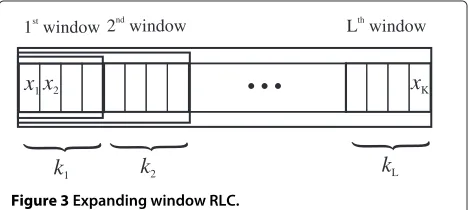
Letx= {x1,x2,. . .,xK}be alayeredsource message con-taining K equal-length source packets classified into L importance layers. The source message starts with the most important base layer (BL) and continues with pro-gressively less important enhancement layers (EL). The subset of the source message containing the l-th layer is denoted as xl and contains kl source packets, where
L
[image:3.595.58.293.623.728.2]i=1ki = K. We denote the subset of the source mes-sage containing the firstl layers asx1:l and the number of source packets in the first l layers is Kl = li=1ki (Figure 3).
The UEP RLC scheme called expanding window (EW) RLC was investigated in [18]. The EW RLC introduces a set of EWs over the layered source message following the importance structure of the message. More precisely, for theL-layer message, the set ofLEWs is defined where the l-th EW, 1 ≤l ≤ L, contains the source block subsetx1:l (Figure 3).
EW RLC encoding
The EW RLC introducesthe probabilistic encoding pro-cessover the set of EWs. For each encoded packet, one of the EWs is first selected using the predefined window
x
1x
2...
x
K1 windowst
2 windownd
L windowth
k
1k
2k
L} }
}
Figure 3Expanding window RLC.
selection distribution(ξ ) = Li=1iξi, whereiis the probability of selection of the i-th window, Li=1i = 1. Then, an encoded packet is created by applying RLC only over the selected window. Arbitrarily many EW RLC encoded packets can be produced by independently repeating the encoding process for each encoded packet.
EW RLC decoding
A receiver collects correctly received EW RLC coded packets and decodes the source message (or subset of its layers) using the standard GE decoder, as if standard RLC is used. An important difference is that the parts of the layered source message could be decoded even if less than Kencoded packets are received.
For more details on the design of EW RLC, we refer the interested reader to [18].
Performance analysis of EW RLC
In the following, we review a simple upper bound for the set of decoding probabilities Pd,l(N) that the con-tent of thel-th window, 1 ≤ l ≤ L, is recovered at the receiver after receiving anyNEW RLC encoded packets. The upper bound is general and holds for any packet-level coding and decoding scheme that applies probabilistic encoding and expanding windowing approach. Moreover, the EW RLC in combination with GE decoding achieves this bound as the field size increases [18].
Let y = {y1,y2,. . .,yN} be a sequence of N received EW RLC encoded packets. For the derivation of upper bounds,yis completely described by the corresponding vector n = {n1,n2,. . .,nL}, where nl denotes the num-ber of received packets obtained by EW RLC coding over thel-th window. We denote byyl (andy1:l, respectively) the subset of ycontaining the set of nl
Nl=li=1ni
received packets obtained by EW RLC encoding over the l-th (the firstl) window(s).
For a givenn, we define a set of variablesRl(n), 1≤l≤ L, using the following recursion:
R1(n)=min(n1,K1),
Rl(n)=min(Rl−1(n)+nl,Kl), 2≤l≤L. (1)
Thus any receivedycan be recursively transformed into R= {R1(n),R2(n),. . .,RL(n)}.
windows is recovered, i.e., ifRm(n)=Kmfor anyl<m≤ L, because larger windows contain smaller ones.
Formally, the upper bound onPd,l(N)follows by condi-tioning onna:
Pd,l(N|n)=
=I
⎛
⎝Rl=Kl
L
i=l+1
⎛ ⎝i−1
j=l
(Rj<Kj)∧(Ri=Ki) ⎞ ⎠ ⎞ ⎠,
(2)
whereI(·)represents an indicator function equal to 1 if its argument, which is a logical expression, is true, otherwise, I(·)=0, andi()(j()) is logical or (and) of a sequence of logical expressions parametrized byi(j). Conditioning onnis removed using the prior distribution overn:
P(ξ ),N(n)=
N! n1!n2!. . .nL!
n1
1
n2
2 . . .
nL
L . (3)
Finally, upper bound onPd,l(N)is obtained as:
Pd,l(N)≤
(n1,n2,...,nL): L i=1ni=N
P(ξ ),N(n)Pd,l(N|n). (4)
For a given layered source message, Pd,l(N) depends only on the selected window selection distribution(ξ ).b Therefore, designing EW RLC codes with desiredPd,l(N) behaviour reduces to the design of appropriate(ξ )[18].
Multi-user video streaming using UEP NC System model
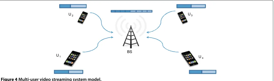
In this article, we propose the UEP NC as a core compo-nent of a real-time multi-user video streaming system. For simplicity, we focus on a wireless cellular network exam-ple whereNumobile users (U1,U2,. . .,UNu) participate in
a multi-party video conferencing session over a common base station (BS) within a single cell (Figure 4).
The presented results are applicable in similar scenarios, e.g., if instead of a single BS users connect to different BSs mutually interconnected by high-speed links (e.g., fiber optic) or if instead of a cellular network we observe a Wi-Fi access point.
In our scenario, every user continuously segments its own video stream into groups of frames (GOF), where each GOF contains Ngof frames, and compresses every GOF using a scalable video coder. For each userUi and each compressed GOF, the output of the video coder is a layered source messagex(i)that containsK(i)source pack-ets, each of length bbits, organized intoLlayers, where the l-th layer containskl(i) packets. The values ofb and Lare the same across all users whereas for each userUi and each GOF, the valuesK(i)and{k(1i),k2(i),. . .,kL(i)}are in general different.
Video streaming among users in a session may be observed as a GOF-by-GOF exchange process. A single GOF exchange period repeats everyTgof=Ngof/Nfps sec-onds, whereNfps is the number of frames per second of the video stream, and bothNgofandNfpsare equal across all users. For simplicity, we assume that GOF periods are aligned among different users, i.e., the messagesx(i) are synchronously generated by all the users. For every GOF period, the goal of each user is to share its own and col-lect other users GOFs, or at least as many of their layers starting from the beginning onwards, within a strict delay limits.
During each GOF period, the data exchange process can be divided into two phases. In the first, upload phase, users simultaneously upload their data to the BS, and in the second, broadcast phase, the BS broadcasts the received data to all the users. We assume that orthog-onal channels are allocated between each user and the BS, and for the broadcast transmission by the BS, allow-ing for simultaneous transmission on all channels. Each wireless link is modeled as a synchronous time-slotted packet-erasure link where the fixed size encoded packets of length b bits are transmitted using a fixed transmis-sion data rate R and erasure probability . We assume
U1
U2 U3
[image:4.595.61.540.584.726.2]U4 BS
that the pair (R,) is in general different on different wire-less links, it remains fixed during the transmission period Tgof of a single GOF, and may change between different GOF transmissions. The time slot duration Tp = b/R represents a time required for a single encoded packet transmission.c
In the upload phase, to protect data from erasures, the user Ui encodes the source message x(i) using the EW RLC scheme defined by a window selection distribution
(i)(ξ )and streams the encoded packets using the user rateR(i). The BS recovers the users’ messages using Nu independent GE decoders dedicated to different users. After decoding as many user layers as possible, the BS cre-ates its own source message x(BS) that contains all or a subset of users’ message layers. For example, if allNuusers are completely recovered, the messagex(BS)is of length K(BS) = Nu
i=1K(i) packets and containsLlayers. Thel -th layer x(BS)l comprises the total of kl(BS) = Nu
i=1k
(i)
l packets from thel-th layer data of allNu user messages, xl(BS) = {x(l1),xl(2),. . .,x(Nu)
l }, as illustrated in Figure 4 for the two-layer scenario. In general, the BS may create the l-th layerx(lBS)from thel-th layers of a subset of users.
In the broadcast phase, the BS applies the EW RLC scheme defined by a window selection distribu-tion (BS)(ξ ) over x(BS) and broadcasts the stream of encoded packets using the broadcast rate R(BS). Each user recovers the BS messagex(BS)using the GE decoder where, prior to decoding, the user cancels out its own packets from the received encoded packets. We note that the two phases may overlap in time, i.e., the BS may start broadcasting a subset of (already recovered) layers of x(BS) before the upload phase of all users is completed.
Single-link analysis: decoding and delay performance To analyze the system in Figure 4, we focus on a single-link transmission of UEP RLC coded layered message between any transmitter-receiver pair during a fixed time periodT. Instead of layer decoding probabilities after fixed number of received packets,Pd,l(N)(Section “Performance anal-ysis of EW RLC”), we shift our interest to layer decoding probabilities after fixed transmission time,Pd,l(T). How-ever, unlikePd,l(N), derivingPd,l(T)requires introduction of a packet-level channel model.
During the period of durationT, the transmission pro-cess consists ofNT = RT/bencoded packet transmis-sions (packet slots). We redefine the received sequence y = {y1,y2,. . .,yNT} to describe the outcome of all
NT transmissions, where yi may represent either the received encoded packet or a lost (erased) packet. The received sequence y can be described by vector n =
{n1,n2,. . .,nL,ne}, where, as before,ni is the number of received encoded packets obtained by encoding over the
i-th EW, N = Li=1ni ≤ NT is the number of (cor-rectly) received encoded packets during the interval T, andne=NT−Nis the number of erased packets.
For a fixed T, the number of received encoded pack-etsNis dependent on the underlying channel packet-loss model. For simplicity, we assume a packet erasure chan-nel model that erases encoded packets independently with erasure probability. To obtainPd,l(T), we use condition-ing overn:
Pd,l(T)=
n
P(ξ ),(n)Pd,l(T|n), (5)
where P(ξ ),(n) is slightly altered version of (3) that
accounts forneerased packet events:
P(x),(n)=
NT! n1!n2!. . .nL!ne!·
(6)
·[1(1−)]n1[2(1−)]n2. . .[L(1−)]nL·()ne. Pd,l(T|n)can be obtained as the layer decoding probability Pd,l(N|n)afterNreceived encoded packets (Section “Per-formance analysis of EW RLC”, Equations (1)–(2)) since, by knowingn, we directly obtainN=Li=1ni.
The knowledge ofPd,l(T) implicitly provides informa-tion on the decoding delay of the l-th message layer. For example, one can search for minimal transmission period Tth(l) such that the l-th message layer decoding probability Pd,l(Tth(l)) > Pth(l), where Pth(l) is the thresh-old decoding probability set in advance. For more explicit delay information, one can obtain the probability distri-bution pd,l(NT) that thel-th message layer is recovered after exactly theNT-th time slot (and cannot be recovered before):
pd,l(NT)= (7)
= NT−1
i=1
(1−Pd,l(T =i·Tp))·Pd,l(T =NT·Tp),
andTp=b/R. The expected delayEl[NT] for recovery of thel-th message layer is:
El[NT]= ∞
NT=1
NT ·pd,l(NT). (8)
The expected delay of recovery of the complete source messageE[NT] for the EW RLC scheme is equal to the recovery delay of the lastL-th layer: E[NT]= EL[NT].
El[NT] is expressed in terms of the number of time slots, but it can be easily converted into absolute time values as
El[T]=E[NT]·Tp.
Example 1. Letxbe a layered source message containing K = 60source packets of size b = 3, 200bits (400 bytes) divided into L=2layers: the BL containing k1=20
0 0.05 0.1 0.15 0.2 0.25 0
0.1 0.2 0.3 0.4 0.5 0.6 0.7 0.8 0.9 1
T [s] Pd,1
(T), P
d,2
(T)
P
d,1/2(T) Γ1=0
Pd,1(T) Γ1=0.3
Pd,2(T) Γ1=0.3
P
d,1(T) Γ1=0.4
P
d,2(T) Γ1=0.4
P
d,1(T) Γ1=0.5
P
d,2(T) Γ1=0.5
P
d,1(T) Γ1=0.6
Pd,2(T) Γ1=0.6
[image:6.595.60.541.86.271.2]Pd,1(T) Γ1=1
Figure 5Pd,1(T)andPd,2(T)for EW RLC over the range of1values.
scheme defined by(ξ )=1ξ+(1−1)ξ2is applied over
xproducing continuous stream of 400-bytes long encoded packets. The wireless link towards the receiver is modeled as a synchronous rate R = 2Mbit/s link with packet era-sure probability =0.1. Figure 5 presents the evolution of layer decoding probabilities Pd,1(T)and Pd,2(T)over time
T at the receiver for the range of1values. As a baseline
scheme, we start from the middle solid curve for1 = 0,
representing standard RLC applied over the whole message, which results in simultaneous recovery of both message layers. By increasing1, we obtain the UEP effect of the EW RLC scheme, where solid curves for the Pd,1(T)
grad-ually shift to the left, i.e., towards earlier recovery of the most important data. The extreme case of1 = 1results in the earliest recovery of the most important part repre-sented by the leftmost dashed curve. The increase in 1
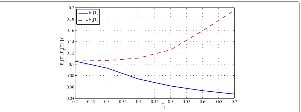
comes at the price of delayed decoding of less important layer Pd,2(T). Figure 6 presents the expected layer decoding
delaysE1[T]andE2[T]as a function of1. Note that
sig-nificant decrease ofE1[T]with the increase in1initally
comes with a relatively small loss inE2[T]. For example,
for1=0.5,E1[T]drops from 105 to 62 ms (−41%) while
E2[T]rises from 105 to 126 ms (+20%).
The single-link analysis can be extended to the scenario where the transmitter changes the applied EW RLC code during the transmission (i.e., switches between different
(ξ )). As an example, we derivePd,l(T)forT >T1, given that the transmitter has applied the EW RLC defined by
a(ξ )during 0 ≤ t ≤ T1, and the EW RLC defined by b(ξ )fort > T1. For the link parametersRand, the transmitter sendsN1 = RT1/bencoded packets using a(ξ )andN2 = R(T −T1)/bencoded packets using b(ξ ). The received sequencey =[y1y2] is a concatena-tion of two sequences y1 and y2 of length N1 and N2, respectively. It can be described by the vectorn=n1n2, where the vectorsn1andn2represent the description of
0.2 0.25 0.3 0.35 0.4 0.45 0.5 0.55 0.6 0.65 0.7
0.04 0.06 0.08 0.1 0.12 0.14 0.16 0.18 0.2
Γ1
E1
[T], E
2
[T] [s]
E 1[T] E
2[T]
[image:6.595.60.541.539.718.2]0 0.05 0.1 0.15 0.2 0.25 0
0.1 0.2 0.3 0.4 0.5 0.6 0.7 0.8 0.9 1
T [s]
Pd,1
(T), P
d,2
(T)
P
d,1(T) Γ1=0.5
P
d,2(T) Γ1=0.5
P
d,2(T) Γ (a) 1=0.5, Γ
(b) 1=0.1
Pd,1(T) − GF(28) −Γ1=0.5
[image:7.595.60.542.86.271.2]Pd,2(T) − GF(28) −Γ1=0.5
Figure 7Pd,1(T)andPd,2(T)for EW RLC which changes(1a)=0.5 to
(b)
1 =0.1at the time instantT1=0.125.
y1 andy2 respectively (as defined earlier), and is the component-wise sum of two equal-length vectors. Since n1 and n2 follow probability distributions P(a)(x),(n1) andP(b)(x),(n2)given by Equation (6), the layer decoding probabilities are obtained as in (5):
Pd,l(T)= (9)
=
n1
n2
P(a)(x),(n1)P(b)(x),(n2)·Pd,l(T|n),
wherePd,l(T|n)follows fromPd,l(N=
L i=1ni|n).
Example 2. We continue Example 1by investigating the evolution of Pd,1(T)and Pd,2(T)over time T at the receiver
if the transmitter appliesa(ξ )=0.5ξ+0.5ξ2for the first T1 = 125ms, and then changes tob(ξ ) = 0.1ξ +0.9ξ2
(the remaining parameters are the same as in the previous example). Figure 7 compares the case wherea(ξ )changes tob(ξ )with the case wherea(ξ )is used throughout the
transmission. Figure illustrates that the(ξ )change has no effect on Pd,1(T)as it comes too late (Pd,1(T1 = 0.125)= 1), whereas the improvement of Pd,2(T) for T > T1 is
notable due to the increase in the second window selection probability from 0.5 to 0.9, which points out to possi-ble adaptive (e.g., feedback-driven) updates of(ξ )during transmission. In addition, Figure 8 demonstrates that the upper bound expressions for Pd,l(T) used in this article match very well the exact calculation of Pd,l(T)for a finite field size GF(28)(markers)[18].
Finally, analytical results presented above can be eas-ily extended to Gilbert–Elliot erasure channel model with two states: the good and the bad state. This follows from the fact that the probability distribution of the numberne of erasures overNT consecutive realizations of the chan-nel (i.e., over time intervalT) is known (e.g., see [26]). The remainingNT −nenon-erased channel realizations deliver encoded symbols from different EWs according to the multinomial distribution law (3).
[image:7.595.57.545.547.715.2]Distortion-optimal system design
In this section, we apply the single-link anaysis to ana-lyze the multi-user video conferencing setup introduced in Section “System model”. Our goal is to formulate the system design problem that leads to the EW RLC code design providing distortion-optimal system performance. As a distortion measure, we use peak signal to noise ratio (PSNR) as a standard video quality metric follow-ing directly from the mean square error (MSE) distortion measure. We use the terms video quality and distortion interchangeably while refering to video quality (PSNR) measure.
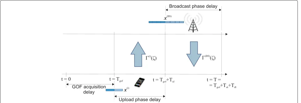
We focus on a single message (GOF) exchange cycle among the system users. After the initial delay of t = Tgofneeded for each user to acquire and compressNgof frames of video (assuming negligible compression delay), the users start the upload phase. During the upload phase, the BS waits to receive enough encoded packets to recover the users’ messages or as many of their layers with suffi-ciently high probability. The upload phase durationTulis upper bounded by the GOF period durationTgofas, after this period expires, users are supplied with a new set of compressed messages, which marks the beginning of the upload phase of the next message exchange cycle. From the set of recovered layers, the BS creates its own mes-sagex(BS)which is broadcasted back to the users over the broadcast downlink channel during the broadcast phase of durationTdl. To simplify the analysis, we assume the upload and the broadcast phase do not overlap, i.e., after the upload phase of duration Tul, the users stop trans-mitting and start listening the BS for the following period of durationTdl. This analysis provides guaranteed (lower-bound) performance for the overlapping phases case, as we discuss later.
We are interested in the system design that maximizes the total average received video quality at the user termi-nals after a given target system delayT =Tgof+Tul+Tdl. Note that, asTgofis constant andT is given in advance, it follows that the system design should optimally bal-ance between theTul andTdl(Tul +Tdl = T −Tgof = const.) The time diagram of the system model, ignoring the propagation and data processing delays, is illustrated in Figure 8.
Upload phase
The upload phase is represented by Nu parallel and independent single-link transmission processes, each characterized by different message/layer sizes (K(i),{k(i)
1 ,k
(i)
2 ,. . .,k
(i)
L }) and channel state pairs (R(i),(i)). Assuming that the user knowsd (R(i),(i)) and that the
value ofTulis fixed in advance by the BS, the set of layer decoding probabilitiesPd(i,−lBS)(Tul)of thei-th user mes-sage at the BS can be calculated for any selected EW RLC parameter(i)(ξ ). In the following, we focus on a simple
user upload strategy where the user applies standard RLC over the largest windowlsuch that the decoding proba-bilityPd(i,−lBS)(Tul) >Pth ∼1 (if such exists), wherePthis a (close to one) value of threshold probability selected in advance. More formally, thei-th user will apply RLC only over thel(i)-th window, wherel(i)is obtained as:
l(i)=maxl:Pd(i,−lBS)(Tul) >Pth
. (10)
Note that applying RLC only over thel(i)-th window is equivalent to the special case of applying UEP RLC with the window selection distribution(i)(ξ ) = ξl(i) (i.e., the one which places probability one on thel(i)-th window).
Overall, the set of Nu users will upload the sub-set of their layers, jointly described by vector l =
{l(1),l(2),. . .,l(Nu)}, within the upload phase of duration
Tul. The probability Pth can be selected so as to keep the overall probabilityP(BS)d,l (Tul) ≥ PthNu that the BS will recover the set of users’ layers described bylduring the upload phase of durationTulsufficiently high.
Broadcast phase
During the broadcast phase, the BS applies the EW RLC code defined by (BS)(ξ ) over the BS message x(BS)(l), which is determined by the set of uploaded user lay-ersl. From l, one can easily obtain the BS message size parameters (K(BS),{k(BS)1 ,k(BS)2 ,. . .,kL(BS)}). The broadcast phase can be also analyzed using the single-link analysis applied on the parameters of the broadcast transmission, as seen by each of the system users. In other words, given
(BS)(ξ ), x(BS)(l) and the BS-to-user-i (BS-i) transmis-sion link parameters (R(BS),{BS−i}1≤i≤Nu), the single-link
analysis provides the set of layer decoding probabilities P(dBS,l−i)(Tdl), 1 ≤ l ≤ L, describing thei-th user capabil-ity to recover the layers of the BS message x(BS)(l) after the broadcast phase. Thus the broadcast phase reduces to the EW RLC design problem for multicast/broadcast setup that aims to simultanously satisfy heterogeneous user link conditions ({BS−i}1≤i≤Nu). This problem has been recently addressed for expanding window fountain (EWF) code design in video multicast setup [27], however, with the difference that in this article, instead of broad-casting a single stream, the BS simultaneously broadcasts a mixture ofNuuser streams.
Each user simultaneously receivesNu−1 video streams originating at the remaining system users. The average received video quality D(i) perceived by thei-th user is
obtained by averaging over the received video qualities of allNu−1 video streams:
D(i)= 1 Nu−1
Nu
j=1,j =i
whereD(ji) is the average received PSNR of thej-th user video content as perceived by thei-th user. D(ji) can be obtained by combining the results of the upload and the broadcast phase analysis:
D(ji)=P(BS)d,l (Tul) l(j)
l=1
Pd(BS,1:−l i)(Tdl)·Dj,1:l, (12)
where the sum is taken over the set ofl(j) ≤ Llayers of thej-th user included inx(BS)(l). In the above expression, Pd(BS-i),1:l (Tdl)is the probability that exactly the firstllayers of the BS messagex(BS)(l)are recovered at the useri:
P(dBS,1:−li)(Tdl)=
⎧ ⎪ ⎪ ⎪ ⎨ ⎪ ⎪ ⎪ ⎩
1−Pd(BS,1−i)(Tdl), l=0 Pd(BS,l−i)(Tdl)·
·(1−Pd(BS,l+−1i)(Tdl)), 0<l<L Pd(BS,l−i)(Tdl) l=L,
(13)
andDj,1:l is the average received PSNR of the j-th user video content after recovery of the firstllayers (averaged over all the frames of the transmitted GOF). Finally, the average received PSNR, averaged across all the users of the multi-user video streaming session, is equal:
D= 1
Nu Nu
i=1
D(i). (14)
System parameters and design
From (11)–(14), by factoring outP(BS)d,l (Tul), we note that the distortion-optimized system design allows for inde-pendent design of the upload and the broadcast phase, given the duration Tul and decoding probability thresh-oldPthare fixed. In other words, by fixing and informing the users on the values ofTul and Pth, the set of layers
l(Tul)that can be reliably uploaded by users in the upload phase can be determined by corresponding users. Conse-quently, the BS messagex(BS)(l)andTdl=T−Tgof−Tul is also determined, which reduces the broadcast phase design to optimization of the EW RLC code parameter
(BS)(ξ )such that the average received video qualityDis maximized after the target system delayT.
Overall, for the distortion-optimized system design, the BS should optimally balance between the upload and the broadcast phase by selecting appropriateTul, appropriate threshold probabilityPth, and optimally satisfy heteroge-neous user requirements by selecting optimized(BS)(ξ ). The optimal solution weights between the number of lay-ers that could be uploaded to the BS with reliabilityPth afterTul and their quality of reconstruction at the set of heterogeneous users afterTdl.
System optimization and results System optimization
For the system model and distortion-optimized design discussed above, the system optimization process is per-formed centrally, e.g., at the video conference server col-located with the central BS node. Given the parameters of all the user messages (K(i),{k(i)
1 ,k
(i)
2 ,. . .,k
(i)
L }), uplink channel conditions (R(i),i) and the broadcast channel conditions (R(BS),{BS−i}1≤i≤Nu), the BS should provide the duration of the upload phaseTul, the threshold proba-bilityPthand the EW RLC code design parameter(BS)(ξ ), such that the average received PSNRDis maximized after the target system delayT. In other words, the BS solves the following problem:
max Tul,Pth,(BS)(ξ )
D, (15)
where 0≤Tul ≤min{Tgof,T−Tgof}and for(BS)(ξ )we have 0≤l(BS)≤1, 1≤l≤LandLl=1l(BS)=1.
Assuming that the BS knows the channel condi-tions (e.g., by measurements and user reporting), it still needs to know the user message parameters (K(i),{k1(i),k2(i),. . .,kL(i)}) to be able to perform the above optimization. Since these data cannot be obtained instan-taneously at the BS, to avoid delays, we assume that the BS uses information available from recent GOF exchanges (e.g., the last GOF or the average over last several GOFs). This way, the BS is able to perform system optimization prior to the start of the upload phase and to broadcast the required parameters Tul andPth back to the users. The users then determine the number of layersl(i)to upload to
the BS and start the upload phase.
Table 1 Parameters of H.264/SVC sequences (L=2,Ngof=4)
Sequence/layers Number of packets Bit rate Y-PSNR
b=3, 200 [bits] [kbps] [dB]
Stefan BL k(11)=20 476.68 28.44
Stefan BL + EL K(1)=60 1432.56 34.53
Foreman BL k(12)=12 282.68 33.62
Foreman BL + EL K(2)=42 992.56 38.63
News BL k(13)=16 379.68 33.47
News BL + EL K(3)=40 948.56 38.36
Coast BL k(14)=20 474.68 30.32
Coast BL + EL K(4)=64 1522.56 34.69
Design examples
The multi-user video streaming system design proposed in this article is illustrated using numerical examples.
Example 3. In this example, we present a distortion-optimized UEP NC solution for the multi-user video con-ferencing system with Nu = 4 users (Figure 4). We assume users perform real-time exchange of H.264/SVC compressed CIF Stefan, Foreman, News and Coastguard sequences (352 × 288, Nfps = 30), each user sharing a
different video sequence. Users encode the sequences into L=2quality layers (BL and one EL) using the coarse-grain scalable (CGS) coding feature. The GOF size is set to very low value of Ngof=4in order to reduce the start-up coding delay Tgof = 4/30= 133ms to the acceptable value. The parameters of the obtained layered source messages, after H.264/SVC compression and averaged over the frames of a sample GOF we use for optimization, are given in Table 1.
For the uplink channel parameters, for each user, we select rate values around 2 Mbps and erasure probabilities in the range = 0.05−0.15: (R(1)=1.5Mbps,1 = 0.07), (R(2)=1.8Mbps,2 = 0.15), (R(3)=2.3Mbps, 3 = 0.05) and (R(4)=1.5Mbps, 4 = 0.12), to account for the vari-ations in particular uplink conditions. The BS broadcast rate is set to R(BS)=6 Mbps and, for simplicity, the broad-cast erasure rates towards each user are set equal to the erasure rates of the corresponding uplink channels, i.e.,
BS−i=i.
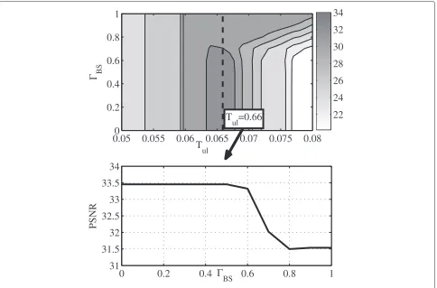
Given the system parameters above, we seek for the optimal system parameters (Tul,(BS)(ξ )) such that the average received PSNR D across all system users is max-imized after the target delay T = 250ms. For simplicity, we fix Pth = 0.99. The solution is illustrated in Figure 9 where average PSNR is plotted as a (two-dimensional) function of (Tul,1(BS)). The system achieves the best
T
ul
Γ
BS0.05
0
0.055
0.06
0.065
0.07
0.075
0.08
0.2
0.4
0.6
0.8
1
0
0.2
0.4
0.6
0.8
1
31
31.5
32
32.5
33
33.5
34
Γ
BSPSNR
22
24
26
28
30
32
34
T
ul
=0.66
[image:10.595.57.541.400.719.2]Table 2 Expected delays in Example 1
Upload El[T][ms] Broadcast El[T][ms]
transmission transmission
U1-BS E1[T]=45.80 BS-U1 E2[T]=41.29
U2-BS E1[T]=25.09 BS-U2 E2[T]=50.20
U3-BS E2[T]=58.58 BS-U3 E2[T]=29.20
U4-BS E1[T]=48.48 BS-U4 E2[T]=43.36
average performance for Tul = 66ms where all users are able to share at least their BL, while user 3 is able to upload both layers to the BS, i.e.,l = (1, 1, 2, 1). For optimal Tul = 66ms, a separate (lower) graph shows the system performance for different EW RLC codes at the BS. Although the maximum of D is achieved over the range of first window selection probabilities(BS)1 , it is favourable to select as large1(BS)as possible to reduce the decoding delay for the first layer, while still maintaining high probability of recovery of the second layer ofx(BS)at all users.e
Table 2 illustrates the average decoding delays for upload and broadcast phase transmisssions for the set of uploaded layers l = (1, 1, 2, 1) and the solution point (Tul,1(BS))=(0.066,0). We can easily note that
the sum of maximum delays experienced during the upload/broadcast phase closely satisfies the delay lim-its imposed by the system: E(22−BS)[T]+E(2BS−3)[T]= 108.78<117=T−Tgof,where maximum upload delay
is below selected upload durationE(22−BS)[T]= 58.58 <
66=Tul.This points out to the possibility of approximated system design using expected delay calculations.
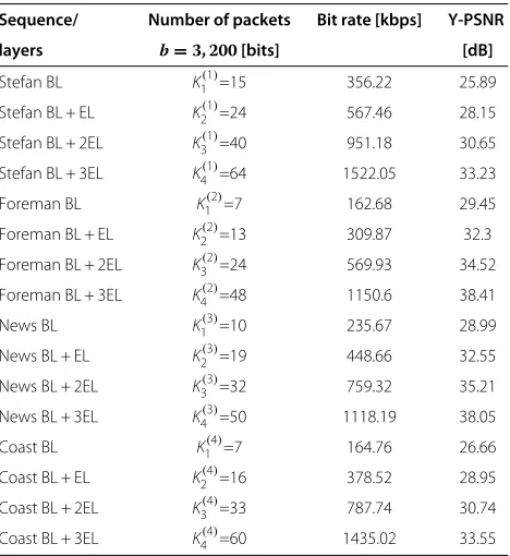
Example 4. Additional flexibility in the system design is obtained if the users compress their video streams into larger number of layers. In this example, we observe the performance of the distortion-optimized system design for the same transmission parameters as in the previous example, but where the layered source message is com-pressed into L = 4 quality layers (see Table 3 for the message parameters). The system performs optimally for Tul = 64ms where users are able to upload the set of lay-ers l = (2, 3, 3, 2), where Pth = 0.99 is assumed fixed. The EW RLC broadcast phase parameters that achieve the optimal value D=34.88are for the window selection dis-tribution(BS)(ξ ) = 0.5ξ +0.5ξ3. We note that the gain obtained in average system distortion D is not large, due to the fact that compressing video into larger number of lay-ers introduces small performance penalties, but the system flexibility reflected through better layer resolution provides more options for the system design process.
Decode-and-broadcast versus buffer-and-broadcast In the proposed system, we applydecode-and-broadcast operation in central multi-user video streaming point: the
uploading streams are firstly decoded and then broad-casted within the non-overlapping broadcasting stage. Clearly, this approach simplifies applications of our ana-lytical tools and enables simple and elegant system design, however, improvements are possible if the broadcast phase is initialized before the incoming user messages are completely recovered. A possible improvements are shortly commented below.
Layer-by-layer decode-and-broadcast
Let us assume the upload phase where a general UEP RLC is applied instead of the specific RLC case that encodes the largest window decodable within Tul. In this case, the unequal recovery time (URT) property enables the central point to decode user layers sequentially over time, starting from the BL onwards [18]. Thus the central point is able to produce encoded packets as soon as the BL of the message x(BS) is decoded and include additional layers as soon as they become available while updating the broadcast EW RLC code parameter(BS)(ξ )“on the fly,” as illustrated in Example 2. We note that this scenario introduces a trade-off between increase in the upload delays of higher layers and decrease in the beginning of the broadcast phase, which has to be balanced by the optimal solution. Unfortunately, the distortion optimized system design for this scenario would result in tedious optimization problem, which is why we leave it out of consideration. However, we note that expected delay analysis, similar to the one presented in Table 2, could
Table 3 Parameters of H.264/SVC sequences (L=4,Ngof=4)
Sequence/ Number of packets Bit rate [kbps] Y-PSNR
layers b=3, 200[bits] [dB]
Stefan BL K1(1)=15 356.22 25.89
Stefan BL + EL K2(1)=24 567.46 28.15
Stefan BL + 2EL K3(1)=40 951.18 30.65
Stefan BL + 3EL K4(1)=64 1522.05 33.23
Foreman BL K1(2)=7 162.68 29.45
Foreman BL + EL K2(2)=13 309.87 32.3
Foreman BL + 2EL K3(2)=24 569.93 34.52 Foreman BL + 3EL K4(2)=48 1150.6 38.41
News BL K1(3)=10 235.67 28.99
News BL + EL K2(3)=19 448.66 32.55
News BL + 2EL K3(3)=32 759.32 35.21
News BL + 3EL K4(3)=50 1118.19 38.05
Coast BL K1(4)=7 164.76 26.66
Coast BL + EL K2(4)=16 378.52 28.95
Coast BL + 2EL K3(4)=33 787.74 30.74
[image:11.595.306.540.479.734.2]be used as a simple approximation for the layer-by-layer decode-and-broadcast system design.
Buffer-and-broadcast
Finally, the simplestbuffer-and-broadcastsolution follows the standard NC approach in which all the received encoded packets are buffered, and new encoded packets produced by applying RLC over the buffer content [6,7]. In the proposed UEP RLC case, the central point main-tainsLseparate buffers, each collecting encoded packets of different users produced over one of theL windows. As soon as the upload phase starts filling the buffers, the broadcast phase starts producing encoded packets where each encoded packet results from applying RLC over one of the buffers selected independently by the appropriate window (i.e., buffer) selection distribution
(BS)(ξ ). Although very efficient, this solution lacks effi-cient analysis and distortion-based optimization tools. In addition, the problem of broadcasting linearly dependent encoded packets may become significant as the upload user rates decrease and broadcast rate increases (i.e., the rate of encoded packets generation exceeds the rate of incoming source data).
Conclusions
Real-time sharing of video content among multiple users over wireless networks is underlying a number of exist-ing and upcomexist-ing mobile multimedia services. For robust, flexible and efficient implementation of such services, this article considered a combination of scalable video coding and UEP NC. We have presented analytical tools capable of producing the values of key system design parameters that result in the distortion-optimal system performance. The applications of the proposed tools are illustrated through several examples involving a simple single access point multi-user scenario.
Endnotes
aFor compactness, we denoteR
l(n)asRl.
bNote that, due to the probabilistic encoding, the
decod-ing performance is independent of the packet erasure process in the channel and depends only on the numberN of received packets.
c This model roughly captures the behaviour of adaptive
modulation and coding (AMC) at the physical layer of cellular systems where, depending on the channel qual-ity feedback available at the BS, different AMC modes could be approximated by different (R,) pairs. We assume slowly-varying channels where AMC mode changes are of the order ofTgof.
d In state-of-the-art wireless cellular broadband systems
such as LTE or WiMAX, channel quality indicators (CQI) are continuously fed back by user equipment to the BS.
eFor presentation purpose, Figure 9 is obtained by
brute-force calculation over a grid of points in (Tul,1(BS)) space. In general, (one of ) the optimal solution(s) can be obtained by applying nonlinear programming meth-ods such as sequential quadratic programming (e.g., using MATLAB).
Competing interests
The authors declare that they have no competing interests.
Acknowledgements
Dejan Vukobratovic was supported by a Marie Curie European Reintegration Grant FP7-PEOPLE-ERG-2010 ”MMCODESTREAM” within the 7th European Community Framework Programme.
Author details
1Department of Power, Electronics and Communication Engineering,
University of Novi Sad, Trg D. Obradovi´ca 6, Novi Sad, Serbia.2Department of
Electronic and Electrical Engineering, University of Strathclyde, 204 George Street, G1 1XW, Glasgow, UK.
Received: 27 February 2012 Accepted: 20 June 2012 Published: 13 July 2012
References
1. H Shiang, M van der Schaar, Multi-user video streaming over multi-hop wireless networks: a distributed, cross-layer approach based on priority queuing. IEEE J. Sel. Areas Commun.25(4), 770–785 (2007)
2. X Zhu, P Agrawal, J Pal Singh, T Alpcan, B Girod, Rate allocation for multi-user video streaming over heterogenous access networks. inACM MULTIMEDIA ’07,(Augsburg, Germany, 2007), pp. 37–46
3. R Ahlswede, N Cai, S yen Robert Li, RW Yeung, Network information flow. IEEE Trans. Inf. Theory.46(4), 1204–1216 (2000)
4. S yen Robert Li, RW Yeung, N Cai, Linear network coding. IEEE Trans. Inf. Theory.49(2), 371–381 (2003)
5. T Ho, M Medard, R Koetter, DR Kargerm, M Effros, J Shi, B Leong, A random linear network coding approach to multicast. IEEE Trans. Inf. Theory.
52(10), 4413–4430 (2006)
6. PA Chou, Y Wu, K Jain, Practical network coding. inAllerton 2003 Conference,(2003)
7. DS Lun, M Medard, R Koetter, M Effros, On coding for reliable communication over packet networks. Phys. Commun.1, 3–20 (2008) 8. C Gkantsidis, P Rodriguez, Network coding for large scale content
distribution. inIEEE INFOCOM 2005,(Miami, FL, USA, 2005), pp. 2235–2245 9. P Chou, Y Wu, Network coding for the internet and wireless networks.
IEEE Signal Process. Mag.24(5), 77–85 (2007)
10. E Magli, P Frossard, An overview of network coding for multimedia streaming. inIEEE ICME 2009,(New York, NY, USA, 2009), pp. 1488–1491 11. J Zhao, F Yang, Q Zhang, Z Zhang, F Zhang, LION: layered overlay multicast
with network coding. IEEE Trans. Multimed.8(5), 1021–1032 (2006) 12. M Wang, B Li, R2: random push with random network coding in live
peer-to-peer streaming. IEEE J. Sel Areas Commun.25(9), 1655–1666 (2007)
13. H Seferoglu, A Markopoulou, Video-aware opportunistic network coding over wireless networks. IEEE J. Sel. Areas Commun.27(5), 713–728 (2009) 14. N Thomos, P Frossard, Network coding of rateless video in streaming
overlays. IEEE Trans. Circ. Syst. Video Techn.20(12), 1834–1847 (2010) 15. H Wang, R Chang, CCJ Kuo, Wireless multi-party video conferencing with
network coding. inIEEE ICME 2009,(New York, NY, USA, 2009), pp. 1492–1495
16. M Ponec, S Sengupta, M Chen, J Li, PA Chou, Multi-rate peer-to-peer video conferencing: a distributed approach using scalable coding. inIEEE ICME 2009,(New York, NY, USA, 2009), pp. 1406–1413
17. H Zhang, J Zhou, Z Chen, J Li, Minimizing delay for video conference with network coding. inACM SIGCOMM 2009,(Barcelona, Spain, 2009) 18. D Vukobratovi´c, V Stankovi´c, Unequal error protection random linear
19. Y Wu, P Chou, SY Kung, Information exchange in wireless networks with network coding and physical-layer broadcast. inProc. CISS 2005,
(Baltimore, MD, USA, 2005)
20. S Katti, H Rahul, W Hu, D Katabi, M Medard, J Crowcroft, XORs in the air: practical wireless network coding. inACM SIGCOMM 2006,(Pisa, Italy, 2006), pp. 243–254
21. U Horn, K Stuhlmuller, M Link, B Girod, Robust internet video transmission based on scalable coding and unequal error protection. Signal Process. Image Commun.15, 77–94 (1999)
22. V Stankovic, R Hamzaoui, Live video streaming over packet networks and wireless channels. inIEEE Packet Video 2003,(Nantes, France, 2003) 23. E Maani, AK Katsaggelos, Unequal error protection for robust streaming of
scalable video over packet lossy networks. IEEE Trans. Circ. Syst. Video Tech.20(3), 407–416 (2010)
24. H Shojania, B Li, Random network coding on the iPhone: fact or fiction? in
ACM NOSSDAV 2009, USA,(Williamsburg, VA, USA, 2009), pp. 37–42 25. P Vingelmann, F Fitzek, M Pedersen, J Heide, H Charaf, Synchronized
multimedia streaming on the iPhone platform with network coding. in
IEEE CCNC 2011, USA,(Las Vegas, NV, USA, 2011), pp. 875–879
26. L Wilhelmsson, LB Milstein, On the effect of imperfect interleaving for the Gilbert–Elliott channel. IEEE Trans. Commun.47(5), 681–688 (1999) 27. D Vukobratovic, V Stankovic, D Sejdinovic, L Stankovic, Z Xiong, Scalable
video multicast using expanding window fountain codes. IEEE Trans. Multimed.11(6), 1094–1104 (2009)
doi:10.1186/1687-1499-2012-218
Cite this article as:Vukobratovi´c and Stankovi´c:Multi-user video
stream-ing usstream-ing unequal error protection network codstream-ing in wireless networks.
EURASIP Journal on Wireless Communications and Networking20122012:218.
Submit your manuscript to a
journal and benefi t from:
7Convenient online submission
7Rigorous peer review
7Immediate publication on acceptance
7Open access: articles freely available online
7High visibility within the fi eld
7Retaining the copyright to your article