This is a repository copy of
Three-phase grid-connected inverters equipped with nonlinear
current-limiting control
.
White Rose Research Online URL for this paper:
http://eprints.whiterose.ac.uk/133294/
Version: Accepted Version
Proceedings Paper:
Dedeoglu, S. orcid.org/0000-0001-7969-011X and Konstantopoulos, G. (2018)
Three-phase grid-connected inverters equipped with nonlinear current-limiting control. In:
Proceedings of 2018 UKACC 12th International Conference on Control (CONTROL).
Control 2018: The 12th International UKACC Conference on Control, 05-07 Sep 2018,
Sheffield, UK. IEEE , pp. 38-43. ISBN 978-1-5386-2864-5
https://doi.org/10.1109/CONTROL.2018.8516764
© 2018 IEEE. Personal use of this material is permitted. Permission from IEEE must be
obtained for all other users, including reprinting/ republishing this material for advertising or
promotional purposes, creating new collective works for resale or redistribution to servers
or lists, or reuse of any copyrighted components of this work in other works. Reproduced
in accordance with the publisher's self-archiving policy.
[email protected] https://eprints.whiterose.ac.uk/
Reuse
Items deposited in White Rose Research Online are protected by copyright, with all rights reserved unless indicated otherwise. They may be downloaded and/or printed for private study, or other acts as permitted by national copyright laws. The publisher or other rights holders may allow further reproduction and re-use of the full text version. This is indicated by the licence information on the White Rose Research Online record for the item.
Takedown
If you consider content in White Rose Research Online to be in breach of UK law, please notify us by
Three-Phase Grid-Connected Inverters Equipped
with Nonlinear Current-Limiting Control
Seyfullah Dedeoglu and George C. Konstantopoulos
Department of Automatic Control and Systems EngineeringThe University of Sheffield Sheffield, S1 3JD, UK
{sdedeoglu1, g.konstantopoulos}@sheffield.ac.uk
Abstract—Voltage source inverters are essential devices to integrate renewable energy sources to the main grid and control the injection of real and reactive power. Due to their inherent nonlinear dynamics, the stability and particularly the current limitation of power controlled inverters represent challenging tasks under grid variations or unrealistic power demands. In this paper, using the synchronously rotating dq transformation, a nonlinear current limiting controller is proposed for three-phase inverters connected to the grid through an LCL filter. The proposed controller introduces a cascaded control structure with inner current and voltage control loops and an outer power controller that includes a droop function to support the grid and rigorously guarantee a limit for the grid currents. Using nonlinear closed-loop system analysis and based on input-to-state stability theory, the limits for the d- and q-axis grid currents are proven independently from each other without adding any saturation units into the system that can lead to instability. Extensive simulation results of the proposed nonlinear current-limiting controller are provided to demonstrate its effectiveness and current-limiting property.
Index Terms—Nonlinear control, three-phase inverter, current limitation, nonlinear stability analysis
I. INTRODUCTION
In contrast to traditional power grids which depend on the centralized generation, the smart grid architecture is based on several distributed generation (DG) units that include renewable energy sources, such as wind turbine generators and photovoltaic systems [1]. However, as the integration of the renewable sources into the grid increases, power system stability has become fragile due to volatility in the supply and demand which affects the frequency and voltage of the grid [2]. Therefore, in order to enhance system reliability and achieve large-scale utilization of DG units and seamless transition between islanded and grid-connected modes without violating the voltage and frequency limitations [3], the design of advanced control methods for the inverter devices that integrate DG systems to the main grid is of major importance [1], [4], [5]. Droop control is one of the most commonly used methods for inverters to support the grid, since it does not require any communication between the DG units and adjusts
This work was supported by the EPSRC under Grant No. EP/S001107/1 and the Innovate UK under Grant No. 103910.
the active and reactive power depending on the grid voltage and frequency [6].
Although droop control has been proven to be a very ben-eficial way to manage the injected active and reactive power independently, in a number of studies such as [7], [8], [9] and [10], the nonlinear dynamics of the controller and the system are often not taken into account and the stability analysis is based on linearization techniques. Since linearization methods confine the region of stability, the accurate nonlinear dynamics of a droop controlled grid-tied inverter should be considered for a rigorous stability analysis [11], [12].
In grid-connected applications, in order to improve the system stability and also protect the inverter and the filter against high currents, a current-limiting property should be additionally guaranteed. For this purpose, additional saturation blocks or limiters are often used in combination with the droop controller [13], [14], and [15]. However, these techniques can lead to instability due to integrator windup. This problem can be alleviated using anti-windup methods [16], [17], but most of the modern anti-windup methods need full information of the system parameters, which are generally unknown, and traditional anti-windup techniques cannot rigorously guarantee closed-loop system stability. To this end, a nonlinear current limiting controller that overcomes these issues has been re-cently proposed for single phase grid-connected inverters in [18], [19] and guarantees current limitation without suffering from integrator windup under both normal and faulty grid conditions. However, this controller cannot be directly applied to three-phase inverters using the dq synchronously rotating reference frame modelling [1] and can only limit the current on the inverter side and not the grid side, which is more important in grid-connected applications.
Rf Lf
Cf Cf Cf
Va Vb
Vc DC
AC
PWM signals Vdc
Rf Lf
Rf Lf
Rg Lg
Rg Lg
Rg Lg Three-phase
[image:3.595.45.284.51.128.2]inverter
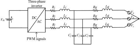
Fig. 1:Three-phase grid-connected inverter with anLCLfilter
in three-phase inverter applications [20]. However, for the outer power loop, a new nonlinear droop controller is pro-posed with bounded voltage dynamics and a constant virtual resistance to guarantee closed-loop system stability and the desired limitation. Using nonlinear Lyapunov methods [21], the boundedness of the controller voltages are analytically proven and then using input-to-state stability, the d- and q-axis grid currents are proven to be limited below a given maximum value independently from each other or the power demand. Hence, the proposed controller introduces a droop control structure to support the voltage and frequency of the grid and at the same time maintains a limited injected current to the grid to protect the inverter under unrealistic power demands. Detailed simulation results of a grid-connected three-phase inverter equipped with the proposed nonlinear current-limiting controller are presented to verify the theoretical analysis.
The rest of the paper is arranged as follows. In Section II, the dynamic model of a three-phase grid-connected inverter is given. In Section III, the proposed controller is presented and the dynamics of the outer power control loop are analyzed to prove the desired current-limiting property. In Section IV, simulation results of a three-phase inverter operating under the proposed controller are provided and in Section V, the conclusions of the paper are drawn.
II. DYNAMIC MODEL OF THE SYSTEM
The system under consideration is a three-phase inverter connected to a balanced grid with angular velocity ωg via
an LCL filter, as illustrated in Fig. 1. The inverter-side filter resistance, inductance, and capacitance are represented byRf,
Lf, andCf, respectively, while grid-side filter resistance and
inductance are denoted asRg andLg. The inverter is supplied
by a dc source denoted asVdc, whileVa,Vb, andVc represent
the three-phase grid voltages. The dynamic model of the system can be obtained using the synchronously rotating dq frame [1], as given below:
Lf
dIf d
dt =−RfIf d+ωLfIf q+md Vdc
2 −VCd (1)
Lf
dIf q
dt =−RfIf q−ωLfIf d+mq Vdc
2 −VCq (2)
Cf
dVCd
dt =If d−Igd+ωCfVCq (3)
Cf
dVCq
dt =If q−Igq−ωCfVCd (4)
Lg
dIgd
dt =−RgIgd+ωLgIgq−Vgd+VCd (5)
Lg
dIgq
dt =−RgIgq−ωLgIgd−Vgq+VCq (6)
whereIf d,If q andIgd,Igq represent the d and q components
of inverter and grid currents, respectively, whereas VCd,VCq
and Vgd, Vgq symbolize the filter and grid voltages in dq
frame. The control inputs of the system are represented bymd
and mq, which are duty ratio functions that drive the PWM
(pulse width modulation) signals for the inverter. Taking into consideration the dq system equivalence, as in [22], the real powerP and reactive powerQof the system can be calculated as
P = 3
2(VCdIgd+VCqIgq), Q= 3
2(VCdIgq−VCqIgd). (7)
As can be seen from (7), due to the multiplication of the system states in the expressions ofP andQ, any controller that requires the calculation of the real and the reactive power, such as the droop controller, will result in a nonlinear closed loop system. Hence, the stability analysis of the closed-loop system and key properties for the inverter, such as current limitation, must be proven using nonlinear systems theory. To this end, the main aim of this paper is to design a nonlinear droop controller for a three-phase inverter that guarantees stability and limits the grid currents under given maximum values at all times.
III. CONTROLLERDESIGN ANDANALYSIS
In order to design the desired droop controller for the inverter, a cascaded control structure which includes inner current and voltage control loops and an outer power control loop is adopted. For the inverter side currents and voltages, the inner loops introduce a PI controller with decoupling terms, while a novel nonlinear droop controller is proposed as the outer loop to limit the grid currents in dq reference frame as presented below in detail.
A. Inner Control Loops
Based on the dq dynamic model of the grid-connected inverter, where md and mq are the control inputs, the inner
current controller that regulates the inverter currents If d and
If q to the desired values Idref andIqref, respectively takes
the form:
md=
(Idref−If d)(Kpi+ KIi
s ) +VCd−ωLfIf q
0.5Vdc
mq =
(Iqref −If q)(Kpi+ KIi
s ) +VCq+ωLfIf d
0.5Vdc
. (8)
Here, a PI controller with additional decoupling terms is applied at the duty-ratio inputsmdandmq, while the reference
valuesIdref andIqref are obtained from a voltage controller
with similar structure:
Idref = (VCdref −VCd)(Kpv+
KIv
s ) +Igd−ωCfVCq
Iqref = (VCqref−VCq)(Kpv+
KIv
s ) +Igq+ωCfVCd (9) where the desired values for the capacitor voltagesVCdrefand
The PI controller gains can be selected accordingly such that the current controller acts much faster than the voltage controller, which acts faster than the power controller. This design of controllers in different time scales can be accom-plished via suitable pole placement and is widely adopted in a cascaded control design approach [23].
B. Proposed Nonlinear Controller (Outer Loop)
Since the fast inner control loops have been extensively investigated in the literature [13] and [23], this paper will focus on the design of the outer droop control loop, which represents the novelty of this work. Based on the fast current and voltage controllers, it is considered that the capacitor voltagesVCdand
VCqare regulated to their reference valuesVCdref andVCqref
in (5) and (6). Then, the proposed controller takes the form
VCdref =Vgd+Ed−rvIgd−ωLgIgq (10)
VCqref =Vgq+Eq−rvIgq+ωLgIgd (11)
In (10) and (11), the parameters Ed and Eq represent two
controllable voltage terms (controller states) that implement the desired droop functions, whilervacts as a positive constant
virtual resistance. Inspired by the universal droop control expressions [24], and the bounded controller designed in [25], the controller statesEd andEq are dynamically formed as
˙
Ed =cd(Ke(E∗−VC)−n(P−Pset))E 2
dq (12)
˙
Edq=−
cdEdEdq
E2 max
(Ke(E∗−VC)−n(P−Pset))
−kd
E2 d
E2 max
+E2 dq−1
Edq (13)
˙
Eq =−cq(ω∗−ωg+m(Q−Qset))E 2
qq (14)
˙
Eqq =
cqEqEqq
E2 max
(ω∗−ω
g+m(Q−Qset))
−kq
E2 q
E2 max
+Eqq2 −1 !
Eqq (15)
where Edq, and Eqq are two additional control states and
cd, cq, Emax, Ke, kd, and kq are positive constants. The
expressionKe(E∗−VC)−n(P−Pset)introduces theP ∼V
droop expression, which should be zero at the steady-state, andE∗ is the rated RMS voltage of the grid, VC is the RMS
voltage of the filter capacitor given asVC= qV2
Cd+V
2
Cq 2 ,Pset
is the reference value of the real power and n is the droop coefficient. Similarly,ω∗−ωg+m(Q−Qset)represents the
Q ∼ −ω droop expression, where ω∗ is the rated angular frequency,ωgis the grid frequency,Qsetis the desired injected
reactive power and m is the second droop coefficient. The P ∼ V andQ ∼ −ω droop expressions are adopted in this paper due to the introduction of the virtual resistance rv in
the output via the proposed control design [24]. The initial conditions of the controller statesEd, Edq,Eq, and Eqq are
selected as 0, 1, 0, and 1, respectively, and the nonlinear dynamics (12)-(15) have been proposed in a way to guarantee the boundedness of the controller states Ed and Eq in the
range Ed, Eq ∈[−Emax, Emax]as explained below.
For the controller dynamics (12) and (13), one can consider a Lyapunov function candidate as
Wd=
E2 d
E2 max
+E2
dq. (16)
The time derivative of this function is
˙
Wd=
2EdE˙d
E2 max
+ 2EdqE˙dq. (17)
By replacing in (17)E˙dandE˙dqfrom the controller dynamics
(12) and (13), then
˙
Wd=−2kd
E2 d
E2 max
+E2 dq−1
E2
dq. (18)
As can be seen from (18),W˙d= 0whenEdq= 0or for every
values of Ed andEdq on the ellipse:
Wd0=
Ed, Edq∈R:
E2 d
E2 max
+Edq2 = 1
. (19)
Based on the initial conditions of the controller states,Edand
Edq will always stay on the ellipse Wd0 as mathematically
expressed below:
˙
Wd= 0 ⇒Wd(t) =Wd(0) = 1, ∀t≥0. (20)
Hence, Ed ∈ [−Emax, Emax], ∀t ≥0. By considering the
transformation
Ed=Emaxsinφ and Edq= cosφ (21)
then taking into account (12)-(13), Ed andEdq will travel on
the ellipseWd0 with an angular velocity
˙
φ= cd(Ke(E∗−VC)−n(P−Pset))Edq
Emax
. (22)
From (22), when Ke(E∗−VC)−n(P −Pset) is zero, the
angular velocity becomes zero and the controller states can converge to the desired equilibrium point defined by the P ∼V droop control. Considering a similar analysis for the controller dynamics (14)-(15), thenEq andEqq are proven to
remain on a similar ellipse
Bq0= (
Eq, Eqq∈R:
E2 q
E2 max
+Eqq2 = 1 )
(23)
and travel with angular velocity
˙
ψ= −cq(ω∗−ωg+m(Q−Qset))Eqq
Emax
. (24)
Therefore, theQ∼ −ωdroop can be implemented in a similar way, while Eq satisfies Eq ∈[−Emax, Emax] ∀t≥0.
It should be noted that, the proposed controller can easily change from the droop control to accurate regulation ofPand Qat their reference values by removing the termKe(E∗−VC)
realized.
C. Stability analysis and current-limiting property
By implementing the proposed controller (10)-(11) into the grid side current equations (5)-(6) and taking into account the fast regulation of the inner current and voltage loops, the closed-loop grid-side current equations are expressed as
Lg
dIgd
dt =−(Rg+rv)Igd+Ed (25)
Lg
dIgq
dt =−(Rg+rv)Igq+Eq (26) It is clear that the dynamics of Igd and Igq can be
han-dled independently taking into account that Ed, Eq ∈
[−Emax, Emax] for all t ≥ 0, as proven in the previous
subsection. Hence for d-axis grid current dynamics (26), consider the Lyapunov function candidate as
V = 1 2LgI
2
gd. (27)
The time derivative ofV is calculated using (25) as
˙
V =−(Rg+rv)Igd2 +EdIgd
≤ −(Rg+rv)Igd2 +|Ed||Igd|. (28)
Thus,
˙
V <0,∀ |Igd|>
|Ed|
Rg+rv
(29)
which proves that system (25) is input-to-state stable by con-sideringEdas the input. Since it is proven that|Ed| ≤Emax,
∀t≥0,thenIgdwill be bounded for allt≥0.In particular, if
initially|Igd(0)| ≤ REmax
g+rv then from the input-to-state stability
analysis, there is
|Igd(t)| ≤
Emax
Rg+rv
,∀t≥0. (30)
In order to limit the currentIgdbelow a maximum valueImax,
the controller parametersEmaxandrvcan be suitably selected
to satisfy
Emax= (Rg+rv)Imax. (31)
By substituting (31) into (30), it is proven that
|Igd(t)| ≤Imax, ∀t≥0, (32)
which proves the desired current-limiting property.
A similar approach for the q-axis grid current dynamics (26) can easily show that if initially it holds that|Igq(0)| ≤ RgEmax+
rv,
then
|Igq(t)| ≤Imax, ∀t≥0. (33)
As a result, the grid currents are proven to remain below a defined maximum value Imax independently from each
order or the nonlinear droop control expressions by suitably selecting the controller parameters Emax and rv according
to (31). This is achieved without using any saturation units, which is a common approach in conventional controllers and can lead to instability [13]-[14]. Since the current-limiting
property is achieved using nonlinear Lyapunov theory and input-to-state stability analysis, then the grid current limitation is guaranteed at all times, even during transients. It is worth mentioning that if |Igd| → Imax or |Igq| → Imax, then
|Ed| →Emax or |Eq| →Emax, respectively, which leads to
Edq→0or Eqq→0 since the controller states are restricted
on the ellipses Wd0 and Bq0. Then from (12) and (14), it
becomes clear that E˙d → 0 and E˙q → 0, which proves
[image:5.595.40.290.263.377.2]that the integration slows down near the limits resulting in an inherent anti-windup property of the proposed controller. This highlights the superiority of the proposed controller with respect to existing approaches that introduce saturation limits and require additional anti-windup mechanisms that further complicate the controller implementation and closed-loop system stability analysis.
TABLE I: System and controller parameters
Parameters Values
Lf, Lg 0.0139H
Rf, Rg 0.8752Ω
n 0.0661
ωg 2π49.97rad/s
Vdc 700V
Ke 10
KP i,KIi 0.3,10
cd 0.65
cq 22.5
Vgd 220
√
2V
Parameters Values
Cf 1.8186µF
rv 2Ω
m 0.0019
kd,kq 1
Imax 2.5A
KP v,KIv 2,10
ω∗ 2π50rad/s E∗ 218V Emax 7.188V
Vgq 0V
IV. SIMULATION RESULTS
In order to validate the effectiveness of the proposed control strategy, a three-phase grid-connected inverter is simulated using the Matlab/Simulink software. The system and controller parameters are given in Table I. In this section, the main aim is to illustrate that the proposed controller can change between set mode, i.e. accurate real and reactive power regulation and droop control mode and at the same time limits the grid currents when an unrealistic power reference value is provided to the controller.
Initially, the set control mode is enabled by removing the termsKe(E∗−VC)andω∗−ωgfrom (12)-(13) and (14)-(15),
respectively, wherePsetandQset are set to zero. At the time
instantt= 1s, the active power reference value Pset changes
to 400W and at t = 2s, it is further increased to 1650W. As it can be seen from Fig. 2, initially P is regulated to the desired 400W value but when Pset becomes very high, the
proposed controller regulates the real power to a lower value. This is because the current Igd tries to violate its maximum
value Imax = 2.5A in Fig. 4 and the proposed controller
0 2 4 6 8 10 Time(s)
0 500 1000 1500 2000
P(Watt), Q(Var)
[image:6.595.317.527.55.359.2]P Q
Fig. 2: Real and reactive power
Pset is decreased to 800W and the real power is regulated
to the desired value after a short transient. At the time instant t= 4s, the reactive power referenceQsetincreases to200V ar
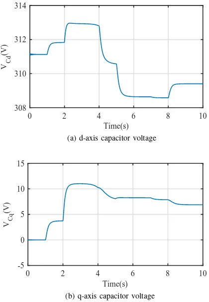
and att= 5it changes to400V arto verify the ability of the controller to regulate the reactive power. As it can be seen from Fig. 2, the reactive power injected by the inverter is accurately regulated to both reference values. TheP ∼V droop control is enabled at t= 7s, and the real power decreases to760W in order to regulate the RMS voltage VC closer to the rated
E∗. The response of the system states VCd andVCq, which
define the RMS valueVC as VC = qV2
Cd+V
2
Cq
2 , is shown in
Fig. 3. At the time instantt= 8s, theQ∼ −ω droop control is enabled and the reactive power is decreased to 301V ar since the frequency of the gridωg is slightly lower than the
rated ω∗, as given in the parameters of Table I. Hence, both accurate regulation of the real and reactive power and droop control modes can be implemented by the proposed nonlinear controller with an inherent grid current limitation that protects the inverter from unrealistic values of the power demand.
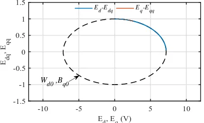
In order to verify the theoretic analysis, the trajectory of the controller statesEd,Edq andEq,Eqq is plotted on theEd−
EdqandEq−Eqq planes, respectively, in Fig. 5 for the entire
simulation. One can easily observe that the controller states remain on the corresponding ellipsesWd0andBq0, which are
the same in this case. From the controller analysis, as the state Edqtends to zero, stateEdreaches its maximum valueEmax,
as shown in Fig. 5, leading to the current-limiting property for Igd. SinceIgqdoes not reach its upper limit (Fig. 4), then the
trajectory of the controller statesEq andEqq remains on the
top of the ellipse Bq0 and is regulated at the corresponding
steady-state values depending on the reference valueQsetand
theQ∼ −ω droop.
V. CONCLUSIONS
A nonlinear current-limiting droop controller for a three-phase inverter connected to the grid through and LCL filter was proposed in this paper. The proposed controller includes traditional PI controllers with decoupling terms for the inner control loops and a nonlinear dynamic controller for the outer
0 2 4 6 8 10
Time(s) 308
310 312 314
V Cd
(V)
(a) d-axis capacitor voltage
0 2 4 6 8 10
Time(s) -5
0 5 10 15
V Cq
(V)
(b) q-axis capacitor voltage
Fig. 3: Filter capacitor voltages
0 2 4 6 8 10
Time(s) 0
1 2 3 4
I gd , I gq
(A)
Igd Igq
I
max=2.5A
Fig. 4: d- and q-axis grid currents
[image:6.595.54.263.58.184.2]-10 -5 0 5 10
Ed, Eq (V)
-1.5 -1 -0.5 0 0.5 1 1.5
Edq
, E
Ed-Edq Eq-Eqq
[image:7.595.54.261.58.183.2]Wd0 ,Bq0
Fig. 5: Controller statesEd, Edq andEq, Eqq
REFERENCES
[1] Q.-C. Zhong, T. Hornik,Control of Power Inverters in Renewable Energy and Smart Grid Integration, New York, NY, USA:Wiley-IEEE Press, 2013.
[2] J. M. Carrascoet al., “Power-Electronic Systems for the Grid Integration of Renewable Energy Sources : A Survey,”IEEE Trans. Ind. Electron.,
vol. 53, no. 4, pp. 1002–1016, 2006.
[3] “The grid code,”National Grid Electricity TransmissionPLC, London, U.K., Tech. Rep., Dec. 2010.
[4] Q.-C. Zhong, G. Weiss, “Synchronverters: Inverters that mimic syn-chronous generators”, IEEE Trans. Ind. Electron., vol. 58, no. 4, pp. 1259-1267, Apr. 2011
[5] J. M. Guerrero, J. Matas, L. G. de Vicuna, M. Castilla, J. Miret, “Decentralized control for parallel operation of distributed generation inverters using resistive output impedance”,IEEE Trans. Ind. Electron., vol. 54, no. 2, pp. 994-1004, Nov. 2007.
[6] Y. Han, H. Li, P. Shen, E. A. A. Coelho, and J. M. Guerrero, “Review of Active and Reactive Power Sharing Strategies in Hierarchical Con-trolled Microgrids,” IEEE Trans. Power Electron., vol. 32, no. 3, pp. 2427–2451, 2017.
[7] R. Majumder, “Some aspects of stability in microgrids”,IEEE Trans. Power Syst., vol. 28, no. 3, pp. 3243-3252, Aug. 2013.
[8] X. Tang, W. Deng, Z. Qi, “Investigation of the dynamic stability of microgrid”,IEEE Trans. Power Syst., vol. 29, no. 2, pp. 698-706, Mar. 2014.
[9] R. Majumder, B. Chaudhuri, A. Ghosh, G. Ledwich, F. Zare, “Improve-ment of stability and load sharing in an autonomous microgrid using supplementary droop control loop”,IEEE Trans. Power Syst., vol. 25, no. 2, pp. 796-808, May 2010.
[10] Y. Mohamed, E. El-Saadany, “Adaptive decentralized droop controller to preserve power sharing stability of paralleled inverters in distributed generation microgrids”,IEEE Trans. Power Electron., vol. 23, no. 6, pp. 2806-2816, Nov. 2008.
[11] J. Schiffer, D. Zonetti, R. Ortega, A. Stankovic, T. Sezi, J. Raisch, “A survey on modeling of microgrids—From fundamental physics to phasors and voltage sources”,Automatica, vol. 74, pp. 135-150, 2016. [12] E. Lenz Cesar, D. J. Pagano, and J. Pou, “Bifurcation Analysis
of Parallel-Connected Voltage-Source Inverters with Constant Power Loads,”IEEE Trans. Smart Grid, vol. 3053, no. c, pp. 1–1, 2017. [13] H. Xin, L. Huang, L. Zhang, Z. Wang, J. Hu, “Synchronous instability
mechanism of P-f droop-controlled voltage source converter caused by current saturation”,IEEE Trans. Power Syst., vol. 31, no. 6, pp. 5206-5207, Nov. 2016.
[14] N. Bottrell, T. C. Green, “Comparison of current-limiting strategies during fault ride-through of inverters to prevent latch-up and wind-up”,
IEEE Trans. Power Electron., vol. 29, no. 7, pp. 3786-3797, Jul. 2014. [15] A. D. Paquette, D. M. Divan, “Virtual impedance current limiting for inverters in microgrids with synchronous generators”,IEEE Trans. Ind. Appl., vol. 51, no. 2, pp. 1630-1638, Mar./Apr. 2015.
[16] L. Zaccarian, A. R. Teel, “Nonlinear scheduled anti-windup design for linear systems”,IEEE Trans. Autom. Control, vol. 49, no. 11, pp. 2055-2061, Nov. 2004.
[17] S. Tarbouriech, M. Turner, “Anti-windup design: An overview of some recent advances and open problems”,IET Control Theory Appl.,vol. 3, no. 1, pp. 1-19, Jan. 2009.
[18] Q.-C. Zhong and G. C. Konstantopoulos, “Current-Limiting Droop Control of Grid-connected Inverters,”IEEE Trans. Ind. Electron.,vol. 46, no. c, pp. 1–1, 2016.
[19] G. C. Konstantopoulos, Q. C. Zhong, and W. L. Ming, “PLL-Less Non-linear Current-Limiting Controller for Single-Phase Grid-Tied Inverters: Design, Stability Analysis, and Operation under Grid Faults,” IEEE Trans. Ind. Electron., vol. 63, no. 9, pp. 5582–5591, 2016.
[20] L. Huang et al., “A Virtual Synchronous Control for Voltage-Source Converters Utilizing Dynamics of DC-Link Capacitor to Realize Self-Synchronization,”IEEE J. Emerg. Sel. Top. Power Electron., vol. 5, no. 4, pp. 1565–1577, 2017.
[21] H. K. Khalil, Nonlinear Systems.Englewood Cliffs, NJ, USA: Prentice-Hall, 2001.
[22] Q.-C. Zhong and G. C. Konstantopoulos, “Current-Limiting Three-Phase Rectifiers,”IEEE Trans. Ind. Electron., vol. 65, no. 2, pp. 957–967, 2018. [23] R. Teodorescu, M. Liserre, and P. Rodriguez,Grid Converters for Pho-tovoltaic and Wind Power Systems,Chichester, West Sussex, UK:Wiley, 2011.
[24] Q. C. Zhong and Y. Zeng, “Universal Droop Control of Inverters with Different Types of Output Impedance,”IEEE Access,vol. 4, pp. 702–712, 2016.