UNIVERSITI TEKNIKAL MALAYSIA MELAKA
DEVELOPMENT OF MOBILE ROBOT FOR SOLVING MAZE
USING ARDUINO
This report submitted in accordance with requirement of the Universiti Teknikal Malaysia Melaka (UTeM) for the Bachelor Degree of Engineering Technology
(Industrial Automation & Robotics) (Hons.)
by
ANIS ATTHIRRAH BINTI SHAMSUL ARIFFIN B071410756
950825-09-5008
UNIVERSITI TEKNIKAL MALAYSIA MELAKA
BORANG PENGESAHAN STATUS LAPORAN PROJEK SARJANA MUDA
TAJUK: DEVELOPMENT OF MOBILE ROBOT FOR SOLVING MAZE USING ARDUINO
SESI PENGAJIAN: 2017/18 Semester 2
Saya ANIS ATTHIRRAH BINTI SHAMSUL ARIFFIN
mengaku membenarkan Laporan PSM ini disimpan di Perpustakaan Universiti Teknikal Malaysia Melaka (UTeM) dengan syarat-syarat kegunaan seperti berikut: 1. Laporan PSM adalah hak milik Universiti Teknikal Malaysia Melaka dan penulis. 2. Perpustakaan Universiti Teknikal Malaysia Melaka dibenarkan membuat salinan
untuk tujuan pengajian sahaja dengan izin penulis.
3. Perpustakaan dibenarkan membuat salinan laporan PSM ini sebagai bahan pertukaran antara institusi pengajian tinggi.
4. **Sila tandakan ( )
SULIT
TERHAD
TIDAK TERHAD
(Mengandungi maklumat yang berdarjah keselamatan atau kepentingan Malaysia sebagaimana yang termaktub dalam AKTA RAHSIA RASMI 1972)
(Mengandungi maklumat TERHAD yang telah ditentukan oleh organisasi/badan di mana penyelidikan dijalankan)
Alamat Tetap:
No.18 A, Lorong Ampang,
Kampung Batu Bertangkup,Jalan Kilang Gula,02500, Chuping, Perlis.
Tarikh: ________________________
Disahkan oleh:
Cop Rasmi:
Tarikh: _______________________
i
DECLARATION
I hereby, declared this report entitled “development of mobile robot for solving maze using arduino” is the results of my own research except as cited in references.
Signature : ……….
Author’s Name : Anis Atthirrah binti Shamsul Ariffin
ii
APPROVAL
This report is submitted to the Faculty of Engineering Technology of UTeM as a partial fulfillment of the requirements for the degree of Bachelor of Electrical Engineering Technology (Industrial Automation & Robotics) with Honours. The member of the supervisory is as follow:
iii
ABSTRAK
iv
ABSTRACT
v
DEDICATION
vi
ACKNOWLEDGEMENT
vii
TABLE OF CONTENT
Abstrak i
Abstract ii
Dedication iii
Acknowledgement iv
Table of Content v
List of Tables vii
List of Figures viii
List Abbreviations, Symbols and Nomenclatures x
CHAPTER 1: INTRODUCTION 1
1.0 Introduction 1
1.1 Background 1
1.2 Problem Statement 4
1.3 Description of prototype 6
1.4 Objectives of Research 6
1.5 Scope of Research 7
1.6 Thesis Outline 8
CHAPTER 2:LITERATURE REVIEW 9
2.0 Introduction 9
2.1 Mobile Robot for Solving Maze Design 9
2.2 Sensor for Maze Wall 13
2.3 Microcontroller and Maze Robot Hardware 14
2.4 Algorithm
2.4.1 Wall Following Algorithm 18
2.4.2 Depth First Search Algorithm 20
2.4.3 Flood-Fill Algorithm 21
2.4.4 Time-Based Diagonal Maze-Solving Robot 22
viii
2.5 Summary 25
CHAPTER 3:PROJECT METHODOLOGY 26
3.0 Introduction 26
3.0.1 First Milestone 28
3.0.2 Second Milestone 30
3.0.3 Third Milestone 30
3.04 Fourth Milestone 31
3.1 Project Methodology 32
3.2 Hardware Development 33
3.3 Software Development 37
3.4 Test Plan 38
3.5 Conclusion 40
REFERENCES 55
ix
LIST OF TABLES
2.1 2.2 2.3
Hardware Components of Half-Size Micromouse Details of Arduino Uno
Data Comparison of Various Maze Solving Method
15 17 25
3.1 Individual Robot Components 33
3.2 Sensor Truth Table that Integrates with Motor 38 4.1 Robot movement calibration using Solidwork and 3D printing
method
45
x
LIST OF FIGURES
1.1 1.2 1.3
International maze track Micromouse robot
Maze solving robot in a maze
2 3 5
2.1 MightyMouse robot 10
2.2 Model of maze solving robot 11
2.3 UTM Micromouse Robot 12
2.4 (a) Half-size micromouse contest in Japan
(b) Comparisons of classic and half-size micromouse 12 2.5 A half-size micromouse sensor position devised in a project
oriented course 13
2.6 Chassis bottom 15
2.7 2.8 2.9 2.10 2.11 2.12 Arduino Uno
Left Wall Following method
Path for depth first search algorithm Flood Fill algorithm
Motion control block diagram for the devised half-size micromouse
The flood values by using the time-based diagonal maze solver
17 19 20 21 23 24 3.1 3.2 3.3 3.4 3.5 3.6 3.7 3.8 Methodology Flowchart Literature Review Flowchart A Maze Solver Robot Base Design Overall Project Development Progress
Position of The Individual Components of the Robot A 4x6 centimetres maze model
A closed loop maze track The real maze track design Project Summarisation Flowchart
xi
4.1 Chasssis design using Solidwork 43
4.2 Chassis design using manual method of cutting perspex 44 4.3 Chassis design using Solidwork and 3D printing 44 4.4 Infrared as the front, left, right sensor of the robot 46
4.5 The sensors position on the robot 47
4.6 Robot testing in basic movement in a maze loop 48 4.7 The designated track maze for the robot to solve 49 4.8 Path to solve the maze using Right Hand Wall Following 50 4.9 Path to solve the maze using Left Hand Wall Following 50 5.1 IR Infrared Line Following Reflective Sensor Module TCRT
5000 53
xii
LIST OF ABBREVIATIONS, SYMBOLS AND
NOMENCLATURE
IDE - Integrated Development Environment IR - Infra-Red
LCD - Liquid Crystal Display LED - Light Emitting Diode SDK - Software Development Kit
1
CHAPTER 1
INTRODUCTION
1.0 Introduction
This chapter provides an introduction to this project. Specifically, it starts with the general information and background about mobile robot of maze solver, project overview, problem statement of this project, description of prototype, objective, scope and it will also cover the thesis outline of the development of the mobile robot for solving the maze using Arduino.
1.1 Background
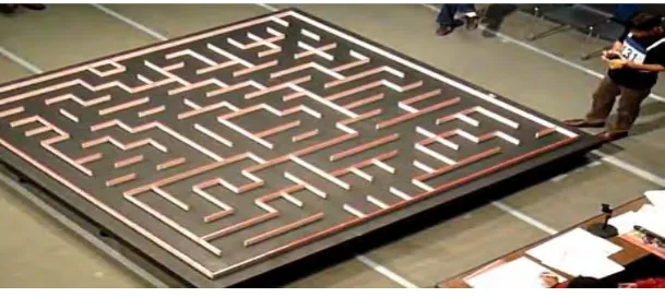
2 starting point of the maze. Figure 1.1 shows the international maze track used as Micromouse robots competition.
Figure 1.1 International maze track
In 1977, the first maze solving robot competition ‘Amazing MicroMouse Maze Contest’ is held to challenge the contestants to design and build a maze-solving “micromouse” robot. The robot should have its own logic algorithm and enough memory. The robot needed to be able to map the given maze in order to achieve the objectives of the competition. The maze design would be held secret until the competition day. Each maze solving robot would be given an opportunity to test run the robot in the maze, and calibrating sensor from the errors to improve its time in the final run. But at the first time trials, only two out of five entries ready that able to get the micro mouse travelled through the maze. However, in 1979 National Computer Conference, the number went increased, about 15 mice successfully competed in the Spectrum finals competition. The micromouse competition had become an international event in just a few years later. Micromouse competetion has continued to spread up to now, when it is about more than 100 contests are held annually including countries from Europe, Japan, Korea and Singapore.
3 first, to determine the shortest path possible to the the center of the maze. As in the competition, the fastest run and the shortest total time consumed for all runs is used as the scoring value.
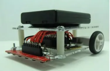
[image:17.595.225.413.571.692.2]Nowadays, the micromouse robots are smaller, lighter, and faster, and they can precise 90 degrees turn smoothly. It is because of the maze robot criterion was lightweight and small in size since it has the crucial task to perform such as the square of turning path. The small robot size is preferable because robot needs space to move smoothly. This robot is moving by itself in the maze, autonomously. The movement of the robot is not controlled manually, it basically depends on algorithm programming. The parts of components for a micromouse include a chassis, wheels, motors and motor drivers, distance or wall sensors, microcontrollers, and batteries. As for electronic components, it used the microcontroller, motors, digital compass, and distance or wall sensors to develop the robot. While for the mechanical parts, the wheel and motor encoder units to support the robot movement and speed, which are also the parts of the motor drive system of the robot. Thus, it can be seen that sensors and motors were the main components because both of the components need to work together in the programming of the robot. The micromouse robot can be seen as a compact system involving many interdisciplinary design challenges and requires various engineering skills, that made it as ‘an international phenomenon’ competition among engineering students especially. Figure 1.2 below shows one of the examples of the maze robot used in the competition.
4
1.2 Problem Statement
For a few decades until today, the micromouse robot challenges can be seen as ‘an international phenomenon’ competition especially among engineering students. Micromouse robot that is a maze solving robot plays a very vital role in solving the maze and offers a variety of engineering skills. Basically, the robot should be able to find the center of the maze with the shortest possible path. However, most of the micromouse robots are still having the problem in solving the maze.
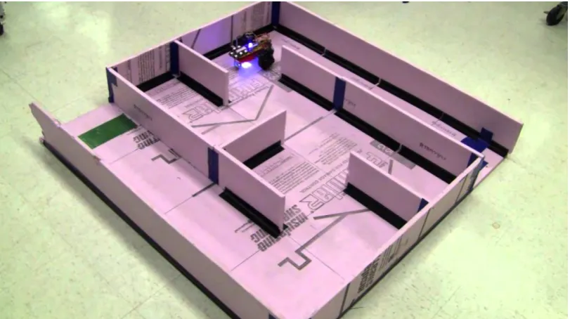
5 Figure 1.3 Maze solving robot in a maze
The robot also has a problem in the programming of the robot movement and path planning (algorithm). Since the robot movement is the most crucial part, so the problem in the robot movement has to be solved first. Then the program of the robot to making a turning within 90 degrees and 180 degrees should be right in order to accomplish the task. If the program used is not right, then the robot will easily crash the wall. Furthermore, if the battery is in low voltage, the robot also will have a difficulty in making a turning. For the robot path planning method, the most efficient algorithm will be chosen. The paths will have a starting and ending points. The problem is, the point of starting position and its end needs to be clarified according to the design or maze task, along with a lot of trials using different algorithm also need to be implemented which consumes a lot of time in order to have the best path planning. The most likely issue is that so far there has also been only a few research on the shortest path maze solving robot.
6
1.3 Description of prototype
a) Autonomous mobile robot
Controlling the robot path movement is depends on the algorithm so it does not need to be controlled manually. The other mobile robots usually require a controller to handle the robot movement. Autonomous robots usually capable of performing tasks in the real life situation by themselves, without the need of human control.
b) Maze solving robot
The maze solving robot is not a line follower robot. Instead of following the line to move, it detects the distance from the wall of the maze as the input data to keep their movement to solve the maze.
1.4 Objectives of Research
Maze solving robot is actually an autonomous mobile robot that employs most technical and coding skills in the engineering point of view. As the way of the maze solver robot are not manually controlled and only depends on algorithm path planning, it serves as a better learning platform as it could help in enhance skills and knowledge, especially in the engineering field. In this project, the project aims to meet the following objectives:
a) To design and develop an autonomous maze solver mobile robot.
b) To verify the algorithm of the autonomous maze solver mobile robot.
7
1.5 Scope of Research
A few guidelines are proposed to ensure that the project will achieve the objectives by narrowing the needs for this project. These are the scopes covered in this project to solve the maze:
a) Using a 4x6 maze track; each cell is 18cm square.
b) Using Left Walll Following algorithm as the path finding method to achieve the objective of this project, to find the shortest path possible to solve the maze.
c) Maze solving robot size is estimated about 12 centimetre width.
d) Using Arduino Uno board for interfacing between all of the components and the chosen path planning algorithm method.
e) Comparing between ultrasonic and infrared sensor as the input devices for robot movement.
8
1.6 Thesis Outline
The structure and layout of the thesis are as follow:
Chapter 1 – Introduction: This chapter briefly explains about the introduction which cover the objectives, scopes of the project and the problem statements.
Chapter 2 – Literature Review: This chapter describes what is Maze Solver Mobile Robot by using Arduino and the existing project with different path planning algorithm which have been developed by the previous researchers. It also consists of the information which will be the parameter for the developing this project.
Chapter 3 – Methodology: This chapter explains about the methodology of this project, which describe details about the method used for developing this project and also approach taken in order to complete the project.
Chapter 4 – Expectation Result: This chapter will consider about the expectation result of the robot to solve the designed maze task.
9
CHAPTER2
LITERATURE REVIEW
This chapter is a review about the journal and article of the related information to the robot for solving maze project. Besides, it contains the description of product that has been developed by certain party, especially students, as a guide and reference of creating the robot. It is focused on design, algorithm, components and sensor of the robot.
2.1 Mobile Robot for Solving Maze Design
10 Reviews of research on Mightymouse, An Autonomous Maze Solving Robot have discovered the maze solver robot and describe knowledgeable information of the robot (Ridge, Sanjeev, Peter, & Jason, 2005). The primary objective of the project is to build an autonomous mobile robot, a micromouse, that able to navigate to the center of a maze. A 16 by 16 cell maze, is to be explored for some time and the robot will make its attempt. The design method of the MightyMouse project consisted of two stages. The first stage was to design and construct individual components. The second stage of the design process was to interface the components to form the final prototype. Secondly, the robot is designed based on IEEE Micromouse Competition criterions and specifications and also the maze itself is built in accordance with IEEE specifications. Both of the objectives are assigned to solve the maze in less than ten minutes, and implementing both a mapping mode and speed run mode. Figure 2.1 below shows the MightyMouse robot project.
Figure 2.1 MightyMouse robot