University of Southern Queensland Faculty of Engineering and Surveying
The Effect of Compression Ratio on the CNG-Diesel Engine
A dissertation submitted by
LIM Pei Li
in fulfillment of the requirements of
Courses ENG4111 and 4112 Research Project
towards the degree of
Bachelor of Engineering (Mechatronic)
ABSTRACT
University of Southern Queensland Faculty of Engineering and Surveying
ENG4111 and ENG4112 Research Project
Limitations of Use
The council of the University of Southern Queensland, its Faculty of Engineering and Surveying, and the staff of the University of Southern Queensland, do not accept any responsibility for the truth, accuracy or completeness of material contained within or associated with this dissertation.
Persons using all or any part of this material do so at their own risk, and not at the risk of the Council of the University of Southern Queensland, its Faculty of Engineering and Surveying or the staff of the University of Southern Queensland.
This dissertation reports an educational exercise and has no purpose or validity beyond this exercise. The sole purpose of the course pair entitled ‘Research Project’ is to contribute to the overall education within the student’s chosen degree program. This document, the associated hardware, software, drawings, and other material set out in the associated appendices should not be used for any other purpose: if they are so used, it is entirely at the risk of the user.
Prof G Baker
Dean
Certification
I certify that the ideas, designs and experimental work, results, analyses and conclusions set out in this dissertation are entirely my own effort, except where otherwise indicated and acknowledged.
I further certify that the work is original and has not been previously submitted for assessment in any other course or institution, except where specifically stated.
Lim Pei Li
Student Number: 0050012455
___________________________ (Signature)
ACKNOWLEDGMENTS
TABLE OF CONTENTS
ABSTRACT i
ACKNOWLEDGMENTS iv
LIST OF FIGURES viii
LIST OF TABLES ix
NOMENCLATURE x
GLOSSARY OF TERMS xiii
CHAPTER I – INTRODUCTION 1
1.1 Introduction 1
1.2 Objectives and Scope 2
1.3 Project Methodology 3
1.4 Dissertation Overview 6
CHAPTER II - LITERATURE REVIEW 7
2.1 Background Information 7
2.1.1 The History on the Usage of Natural Gas 2.1.2 Composition of Natural Gas
2.1.3 Properties of Natural Gas
2.2 Advantage and Disadvantage of Using CNG-Diesel Engine 14
2.3 Conversion of Diesel Engine 16
2.3.1 CNG Dedicated
2.3.2 Dual Fuel (CNG-Diesel)
2.4 Compression Ratio (CR) 19
2.5 Types of Engine Used in term of the Fuel Composition 21 2.5.1 Stoichiometric Burn Engine
2.5.2 Lean Burn Engine
CHAPTER III – PISTON DESIGN WITH INSERTION OF PLATE 25
3.1 Introduction 25
3.1.1 Structure of Piston
3.1.2 Mechanism of Piston in Internal Combustion Engine
3.2 Swirl and Squish Action 30
3.3 Knocking Effect 34
3.4 Piston Design 36
3.5 Design Criteria for the Plate 37
CHAPTER IV – COMPUTATIONAL FLUID DYNAMICS (CFD) 40
4.1 Introduction 40
4.2 Capability of FLUENT Solver 42
4.3 Governing Equations 43
4.3.1 Mass Conservation Equation 4.3.2 Momentum Conservation Equation 4.3.3 Energy Conservation Equation 4.3.4 Turbulent Equation
4.4 FLUENT Solver 48
4.5 Discretization Method 50
4.6 Solution Method 51
4.7 Phenomena Simulated 52
4.7.1 Turbulent Flow 4.7.2 Dynamic Mesh 4.7.3 Non-Reacting Flow 4.7.4 Incompressible Flow
CHAPTER V - DESIGN METHODOLOGY 57
5.1 Engine Specification 57
5.2 Piston Modification 58
5.3.2 Mass Fraction of the CNG-Air Mixture
5.4 Steps for Simulation in FLUENT 65
CHAPTER VI – RESULT AND DISCUSSION 69
6.1 Introduction 69
6.2 Results and Discussion from the CFD Simulation 70 6.2.1 Effects on Using Different Working Medium in
Diesel Engine
6.2.2 CNG-Diesel Engine for Different Compression Ratios 6.2.3 Different Load Conditions for CNG-Diesel Engine with
CR = 19.3:1
6.2.4 Different Load Conditions for CNG-Diesel Engine with CR = 16.6:1
CHAPTER VII – CONCLUSION 82
7.1 Achievement of the Objectives 82
7.2 Recommendation and Future Work 83
LIST OF REFERENCES 85
BIBLIOGRAPHY 87
LIST OF FIGURES
Figure 1.1 – Project Methodology Figure 3.1 – Structure of Piston
Figure 3.2 – Various Shapes of Piston Crown Figure 3.3 – Four-Stroke Cycle
Figure 3.4 – Piston Cup for Swirl Amplification
Figure 3.5 – Swirl Generated by Squish Motion about a Circumferential Axis in Piston Bowl
Figure 3.6 – Generation of Squish and Swirl in a Control Volume of a Piston Bowl Figure 4.1 – Segregated Solution Loop
Figure 5.1 – Simulation Model
Figure 5.2 – Additional Plate to Increase Clearance Volume
Figure 6.1 – Pressure Distribution for Diesel Mode and Dual Fuel Mode Figure 6.2 – Temperature Distribution for Diesel Mode and Dual Fuel Mode Figure 6.3 – Stream Function for Diesel Mode and Dual Fuel Mode
Figure 6.4 – Pressure Distribution for Different Compression Ratios (CR) Figure 6.5 – Temperature Distribution for Different Compression Ratios (CR) Figure 6.6 – Stream Function Distribution for Different Compression Ratios (CR) Figure 6.7 – Pressure Distribution for Different Load Conditions for CR = 19.3:1 Figure 6.8 – Temperature Distribution for Different Load Conditions for CR = 19.3:1 Figure 6.9 – Stream Function Distribution for Different Load Conditions for CR =
19.3:1
LIST OF TABLES
Table 2.1 – Typical Composition of Natural Gas in Malaysia
Table 2.2 – Natural Gas Composition Recommended by the NGV Coalition (U.S.A) for Emission Test Certificate
Table 2.3 – Natural Gas Composition (U.S.A % Europe)
NOMENCLATURE
- Equivalence ratio
φ - Scalar quantity
f - Value of convected through face f
ij - Kronecker delta
ε
- Dissipation rate- Diffusion coefficient for φ
k - Turbulent Prandlt number for turbulent kinetic energy, k
- Turbulent Prandlt number for dissipation factor,
- Gradient of φ
n
)
( - Magnitude of ()normal to face f
A - Surface area
f
A - Area of face
a - Speed of sound
b Bore diameter
CO - Carbon monoxide
CO2 - Carbon dioxide
CH4 - Methane
C2H6 - Ethane
C3H8 - Propane
d - Piston stroke
e - Specific total energy
Fi - External body force from interaction with the dispersed phase
in i direction
gi - Gravitational acceleration k
G - Generation of turbulent kinetic energy due to mean velocity gradients
Gb - Generation of turbulent kinetic energy due to buoyancy
h - Sensible enthalpy
j
h′ - Sensible enthalpy of species j′
j
J - Diffusion flux of species j’
k - Turbulent kinetic energy
eff
k - Effective conductivity
k - Turbulent thermal resistance
L - Length scale
m - Rate of mass of the object generated in the system
j
m ′ - Mass fraction of species j′ faces
N - Number of faces enclosing cell
N2 - Nitrogen
f
n - Number of faces of the control volume
NOx - Nitrogen oxides
O2 - Oxygen
p - Pressure
t
Pr - Turbulent Prandlt number for energy
ρ - Fluid density
S - Source of φ per unit volume
h
S - Additional volumetric heat sources i.e. heat of chemical reaction
ij - Stress tensor
t - Plate thickness
ui and uj - The jth Cartesian component of the instantaneous velocity
- Fluid dynamic viscosity
u - Component of flow velocity perpendicular to the gravitational vector
u - Flow velocity vector
g
u - Grid velocity of the moving mesh
Us - Squish velocity
Up - Instantaneous piston speed
S
V - Swept volume
Vplate - Plate volume
v - Component of flow velocity parallel to the gravitational vector
v - Velocity vector
f
v - Mass flux through the face
Vbowl - Volume of piston bowl or cup Vcup - Volume of piston bowl or cup
YM - Fluctuating dilatation in compressible turbulence to the
overall dissipation rate
N NH
C
Y 2 - Mass fraction of the hydrocarbon
t
GLOSSARY OF TERMS
2D - Two dimensional
3D - Three dimensional
BDC - Bottom dead center CAD - Computer-Aided Drafting CFD - Computational fluid dynamics CNG - Compressed natural gas
CR - Compression ratio
ECU - Electronic control unit EGO - Exhaust gas oxygen
HC - Hydrocarbon
LCA - Lobe Centerline Angle LEL - Lower explosive limit LES - Large eddy simulation NGV - Natural gas vehicle
RAPIER - Rapid analysis of products by integrated engine routine RNG - Renormalization group
CHAPTER I
INTRODUCTION
1.1
Introduction
It is important to understand the function and the operation of the diesel engine before the design stage begins. Therefore, a brief explanation of the operation for a conventional diesel engine is explained below and the main focus is on the compression stroke. The details of the operation in the diesel engine will be explained further in Chapter 3.
• Air flows into the internal combustion engine through the inlet/intake valve during the induction stroke of the piston.
• Then, it is compressed adiabatically to the top dead centre (TDC) of the combustion chamber during the compression stroke. Before the piston reaches the TDC at the end of the compression stroke, fuel (diesel) is injected into the combustion chamber. The mixture of fuel and air would auto-ignite soon after the fuel is injected.
higher the pressure rise rates in the combustion process, the noisier is the diesel engine compared to the gasoline engine (Selim 2003, p.412).
Besides that, it produces gases like carbon monoxide, nitrogen oxides, unburned hydrocarbon, smoke, soot and other forms of black carbon as well as particulate matter such as lead. All the gases are harmful to the environment and human kind. They can cause greenhouse effect, acid rain, ozone thinning and air pollution to the environment. Due to these effects, human will get all kind of diseases such as lung cancer, breathing difficulties, poison and skin cancer.
Therefore, to overcome the above problems, researchers had been investigating into a new engine development to replace the conventional diesel engine. The aim is to develop a more environmental-friendly engine with similar if not better performance as the conventional diesel engine. One such development being investigated is the dual fuel CNG-diesel engine. Since conventional diesel engine operates at a high compression ratio, the compression ratio of the dual fuel system is an area of major concern.
1.2
Objectives and Scope
The main objective of the project is to investigate and simulate the effects of different compression ratios on the engine performance for Compressed Natural Gas (CNG)-Diesel engine. The engine performances mentioned above are in terms of the mixing quality of CNG and air, degree of turbulence in the combustion chamber, pressure and temperature distribution.
As specified in the Project Specification under Appendix A, the sub-objectives are explained below:
• Modify the dimensions of the piston in the combustion chamber to get different compression ratio for the investigation.
• Using CFD simulation software such as FLUENT to simulate a 2D model of the piston in the combustion chamber during compression stroke to investigate the pressure and temperature distribution as well as the stream function.
• Select the optimum compression ratio that delivered optimum combustion efficiency without knock.
1.3
Project Methodology
The execution of the research project is planned in several stages. After the project is allocated and approved by the examiner and staff of ENG4111, the next step is to specify the details of the project such as the objectives, the requirements and the plan for the project workload. At the same time, research and literature survey are carried out to find the requirements for the design of the piston in the combustion chamber and other information related to the project.
The literature survey undertaken is mainly from the books, journal papers and information from the Internet. After that, a review is written to explain, summarize and critically report on all other relevant information found in the materials mentioned. The review should summarize the basic principles used for the design of the piston in dual fuel engine. Besides that, information on the compression ratio, properties and composition of CNG and emission control are equally important to make use of their advantages to the design project.
in terms of simulation would be performed for both the diesel and mixture of CNG-diesel fuel to see the comparison.
Modeling and simulation procedures are carried out by using computational fluid dynamics (CFD) simulation software such as FLUENT 6.1 and the modeling software like GAMBIT 2.1. Simulation is carried out for different compression ratio by using different thickness of plate on the piston head to increase the clearance volume in the combustion chamber. The objectives are to simulate and analyze the result of the pressure distribution, temperature distribution and the stream function in the combustion chamber when piston is compressed by using dynamic meshing method in FLUENT.
All the simulation will be on the analysis of the mixing quality of CNG and air, and pure air also. If the mixture is homogeneously mixed, then the combustion efficiency would be better. Finally the optimum compression ratio is chosen after all the results are obtained and analyzed. The optimum compression ratio for the CNG-diesel engine must provide a similar or better performance than the conventional diesel engine.
Figure 1.1 - Project Methodology Project Allocation
& Approval
Project Specification
Literature Survey & Research
Literature Review & Project Appreciation
Analysis using CFD simulation
software- FLUENT
1.4
Dissertation Overview
This dissertation is divided into seven chapters. Chapter 1 is the current chapter, which introduce the research topic to the reader and explained on the objectives, scope of the research and the project methodology. The following Chapter 2 will summarize the details on the literature reviewed earlier before commencing on the design stage. Among the topics reviewed and covered in this chapter are about the characteristic and properties of natural gas, operation of diesel engine and dual-fuel engine, and compression ratio.
Next, in Chapter 3, the piston design and the types of piston dimensions are explained. Besides that, the operation of the engine is discussed further in this chapter as well as the introduction to the swirl amplification. After the explanation on the piston design, the following Chapter 4 will focus on the theoretical explanation of the method used in the computational fluid dynamic analysis such as the continuity equations of mass, momentum and energy.
CHAPTER II
LITERATURE REVIEW
2.1 Background Information
2.1.1 The History on the Usage of Natural Gas
Natural gas was first used as fuel in China during the Shu Han dynasty in AD221-263. The gas was obtained from shallow wells near seepages and was distributed locally through piping made of hollowed-out bamboos. Since then, there are no records on the usage of natural gas until the early 17th century in Northern Italy, where it was used as a fuel to provide lighting and heating (Tiratsoo 1979, p.8). As the time moves on, the usage of natural gas spread to North America, Canada, New Zealand and Europe. The usage was limited to domestic and industry heating.
The usage of natural gas as a vehicle fuel was discovered back in the early 1920s in Italy. The usage was not popular then due to the fact that natural gas was more commonly used in domestic and industry heating as well as to generate electricity. However, after the World War 2, there is growing interest on the usage of natural gas as vehicle fuel. This interest had led to establishment of approximately 1200 refueling stations and 1500 sub stations for natural gas in Italy by the early 1950s (Shamsudin & Yusaf 1995, p.101).
In 1991, Italy became the leading country in the research of natural gas vehicles. Italy had about 235 000 gasoline vehicles and 20 diesel vehicles that were converted to natural gas (Shamsudin & Yusaf 1995, p.102). Natural gas is compressed in a high pressure tank of 18-20MPa to form compressed natural gas (CNG). The country with the second highest natural gas vehicles is Argentina, which has about 100 000 gasoline vehicles and 10 converted diesel vehicles (Shamsudin & Yusaf 1995, p.102). By 2003, Argentina overtook Italy and became the leading country in the world to convert vehicles to use CNG (Year-end 2003 Refining Margins Dip, then Recover 1 April 2004 <http://www.hydrocarbonprcessing.com>).
The trend towards converting gasoline and diesel vehicles to use CNG is still quite unpopular in Malaysia, compared to more developed western countries. However, due to the limitation of the crude petroleum oil reserves, which should last for another 15 years, Malaysia has since resolved to do more researches and experiments to use alternative fuels like natural gas. This is because the country natural gas reserves would last for about 80 – 90 years. Review showed that up until December 1994, there were about 900 vehicles converted to use CNG as fuel in Malaysia (Shamsudin & Yusaf 1995, p.103).
2.1.2 Composition of Natural Gas
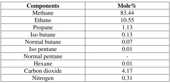
Generally, natural gas is one of the hydrocarbon families, made up of carbon and hydrogen atom. There are different compounds in natural gas such as methane, ethane, propane and iso-butane as well as other non-hydrocarbon compounds such as carbon dioxide and nitrogen. The natural gas found in Malaysia and used in this project is assumed to consist of mainly methane, ethane and propane. Their respective composition percentage of the typical natural gas found in Malaysia is shown in Table 2.1.
Components Mole%
Methane 83.44
Ethane 10.55
Propane 1.13
Iso butane 0.13
Normal butane 0.07
Iso pentane 0.01
Normal pentane -
Hexane 0.01
Carbon dioxide 4.17
[image:23.595.133.469.296.460.2]Nitrogen 0.31
Table 2.1 - Typical Composition of Natural Gas in Malaysia (Yusaf et al., cited in Heath 1996, p.20)
It is very important to know the composition of the natural gas used for the analysis because different composition has different effect on the combustion process in the diesel engine. Unfortunately, there is no standard reference for the design of a standard CNG-diesel engine because the natural gas composition varies in different countries. This posed a problem to the engineer in designing the fuel feeding system and the injection system for the CNG-diesel engine.
like propane and ethane, the main characteristic of natural gas can be directly related to the characteristic of methane.
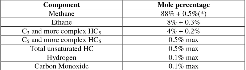
To configure this problem with variation of natural gas composition, the Natural Gas Vehicles (NGV) Coalition in USA has recommended a general guideline of natural gas composition used for the emission test certificate. This test is carried out to help the certification of the engine’s performance and its exhaust gas pollution characteristics that are affected by the gas composition (Bassi 1990, p.740).
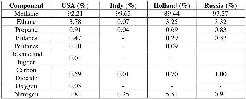
This guideline of the natural gas composition is shown in Table 2.2 in terms of mole percentage. The data provided in Table 2.2 is based on the test carried out during the absence of liquid over the whole range of temperatures and pressures encountered in the engine and in the fuel supply system. Moreover, it is based on the average natural gas composition in USA and Europe as shown in Table 2.3.
Component Mole percentage
Methane 88% + 0.5%(*)
Ethane 8% + 0.3%
C3 and more complex HCS 4% + 0.2%
C5 and more complex HCS 0.5% max
Total unsaturated HC 0.5% max
Hydrogen 0.1% max
Carbon Monoxide 0.1% max
[image:24.595.107.506.403.517.2]Note : - (*) expressed as % of total present organic carbon.
Component USA (%) Italy (%) Holland (%) Russia (%)
Methane 92.21 99.63 89.44 93.27
Ethane 3.78 0.07 3.25 3.32
Propane 0.91 0.04 0.69 0.83
Butanes 0.47 - 0.29 0.37
Pentanes 0.10 - 0.09 -
Hexane and
higher 0.04 - - -
Carbon
Dioxide 0.59 0.01 0.70 1.00
Oxygen 0.05 - - -
[image:25.595.82.513.70.244.2]Nitrogen 1.84 0.25 5.51 0.91
Table 2.3 – Natural Gas Composition (U.S.A & Europe) (Bassi 1990, p.741)
From the information given above, the composition of natural gas affects its properties no matter is physically or chemically. This is the reason to the difficulties faced by engineers all around the world to configure their engine design since every gas field in every nation has its own natural gas composition.
2.1.3 Properties of Natural Gas
Physically, natural gas is colorless, tasteless, relatively non-toxic (Yusaf et al. 1996a, p.19) and not a volatile organic compound (VOC) (Green Mission-Compressed Natural Gas a Fact File 5 February 2004 <http://www.gasmancng.com>). It exists in our environment at normal temperature and pressure, which gave it its name. To use natural gas as fuel in vehicles, it has to be compressed at a high pressure of about 18-20MPa at normal temperature in vessels before it can be supplied to the engine’s combustion chamber. Generally, natural gas is lighter than air with a vapour density of 0.68 relative to air (Why Natural Gas: Economic, Environmental Pollution, Safety, Properties, Composition and Availability 1995, p.10). Therefore, if leaking happens, it will not cause explosion but instead it will disperse to the atmosphere.
spark or flame (Clean Air Program - Assessment of the Safety, Health, Environmental
and System Risks of Alternative Fuel 2 April 2004
<http://ntl.bts.gov/DOCS/afrisks.html#toc>). Higher ignition temperature means that natural gas is more difficult to ignite. This can significant reduce the fire hazard, and constitute anti-knocking ability especially when it is compressed in a very high pressure in the combustion chamber. This property is certainly useful for the design of a dual-fuel engine. The ignition temperature for natural gas is about 900 K.
(Compressed Natural Gas 11 March 2004
<http://www.mckenziecorp.com/dehydration.htm>).
Other physical properties such as the flammability limits range, octane rating, Wobbe Index and flash point also play an important role in the analysis of compression ratio and combustion efficiency of the engine. The Wobbe Index is a measure of the fuel interchangeability with respect to its energy content and the air-fuel ratio (CNG Engine Performance 1995, p.2). Flash point is the minimum temperature for an ignition. The flash point for natural gas is approximately 180° at normal pressure as shown in Table 2.4 in next page.
The flammability limit range is the concentration of natural gas in air to cause an explosion. This is between the lower explosive limit (LEL) of 5% to the upper explosive limit (UEL) of 15% (Clean Air Program - Assessment of the Safety, Health,
Environmental and System Risks of Alternative Fuel 2 April 2004
<http://ntl.bts.gov/DOCS/afrisks.html#toc>). If the concentration of natural gas is more or less than this range, an explosion would not occur. This will certainly reduce the risk of explosion of CNG in air due to leaking because natural gas can only burn in air when the concentration of CNG is high. With this wide range of limits shown in Table 2.4 in the following page, a lean mixture of CNG and air can be used for the CNG-diesel engine to promote better exhaust emission properties.
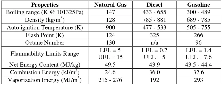
knocking or detonation. Table 2.4 shows the comparison for the general properties of natural gas, diesel and gasoline. Other properties such as the energy content, boiling points, density, combustion energy and vaporization energy have been included in Table 2.4 below:
Properties Natural Gas Diesel Gasoline
Boiling range (K @ 101325Pa) 147 433 - 655 300 - 489
Density (kg/m3) 128 785 - 881 689 - 785
Auto ignition Temperature (K) 900 477 - 533 505 - 755
Flash Point (K) 124 325 266
Octane Number 130 n/a 96
Flammability Limits Range UEL = 15 LEL = 5 LEL = 0.7 UEL = 5 UEL = 7.6 LEL = 1.4
Net Energy Content (MJ/kg) 49.5 43.9 43.5 - 44.4
Combustion Energy (kJ/m3) 24.6 36.0 32.6
[image:27.595.82.513.195.361.2]Vaporization Energy (MJ/m3) 215 - 276 192 293
Table 2.4 – Properties of Natural Gas, Diesel and Gasoline Fuel (Compressed Natural Gas 11 March 2004 <http://www.mckenziecorp.com/dehydration.htm >)
The chemical properties of the natural gas are important for the selection of natural gas as the vehicle fuel. Very often, natural gas is said to be a clean fuel because it is lead free, has a lower emission for carbon dioxide (CO2), carbon monoxide (CO),
nitrogen oxides (NOx) and unburned hydrocarbon compare to the emission produced
by diesel engines (Yusaf et al. 2001b, p.58). All the emission gases mentioned are a major hazard to human being and the environment.
The given properties of natural gas, which is mainly consists of methane is a big influence to the CNG-diesel engine conversion process. For a better understanding on the reason for choosing CNG in the dual fuel engine conversion, its advantages and the disadvantages of dual fuel engine are presented in the next section.
2.2 Advantage and Disadvantage of Using CNG-Diesel Engine
The advantage of converting conventional diesel engine to dual fuel CNG-diesel engine is to convert the engine back to 100% diesel operation easily. It does not require a spark ignition or an electrical system to start the combustion process (Shamsudin & Yusaf 1995, p.104). Instead like spark ignition engine operating on premixed combustion process, the dual fuel engine works in a diffusion combustion process with a high pressure.
Besides that, conversion of diesel engine is more economical than conversion of spark ignition engine due to less modification on the original diesel engine (Shamsudin & Yusaf 1995, p.104). Since dual fuel engine operates at low compression ratio such as 16:1, the original diesel engine only needs minimum modification to suit the CNG-diesel operation. Therefore, the cost of conversion for CNG-diesel engine is lower compared to spark ignition engine.
Another advantage of using CNG-diesel engine is the increase in power output compared to the original diesel engine, which must be within the range of up to 3000rpm (Yusaf et al. 2001b, p.64). If more than 3000rpm, the power output of CNG-diesel engine would decrease slowly due to knocking in the rapid combustion process. Since CNG has high octane rating and high ignition temperature, the CNG-diesel engine has a higher resistant to knock than the conventional diesel engine. However, mild knock still will occur; hence a careful consideration for the compression ratio is necessary to minimize the knock.
good energy security because it produces less hazardous emissions such as carbon monoxide, nitrogen oxides, sulphur oxides and particulate matters. Moreover, the benefits and the good properties of methane as the main component in natural gas reduce the risk of explosion when leakage occurs.
However, there still exist some limitations to the CNG-diesel engine. For instance, the fuel control system is more complicated compared to the spark ignition system (Shamsudin & Yusaf 1995, p.104). Adjustment to the mixing ratio of CNG-diesel and the control of the injector pump are difficult to set correctly for a homogeneous mixture. The variation in the composition of natural gas around the world creates difficulties to certificate the engine performance and exhaust pollution characteristic in the fuel control system.
Another important disadvantage of CNG-diesel engine that caused significant withdrawal from vehicle buyers is the supply system. Normally, dual fuel vehicles need to have separate tanks to store the natural gas in compressed tanks, which are in liquid form. This increases the weight of the vehicle (Weaver, P.E & Lit 2002, p.2) causing reduced power output, limited storage space and posing other drivability problems to the vehicle owner.
The refueling time is longer approximately twice as much as the refueling time for normal gasoline vehicles. There are lesser refueling station for natural gas compared to other conventional fuel such as diesel and gasoline (Weaver, P.E & Lit 2002, p.2). Moreover, it has shorter driving range due to lower energy density of natural gas. Lastly, it has a low efficiency when operating in part load or no load condition (Shamsudin & Yusaf 1995, p.104) but this disadvantage is not significant because the vehicle would be in idling position.
2.3 Conversion of Diesel Engine
There are two methods of converting diesel engine to utilize natural gas as the main vehicle fuel in diesel engine. The first method is to utilize CNG fully in diesel engine known as the CNG dedicated conversion. The second method is the dual fuel conversion using CNG and diesel fuel to ignite the flame in the combustion chamber.
2.3.1 CNG Dedicated
The diesel engine for this type of conversion used 100% CNG to operate it. Therefore, only CNG is injected into the combustion chamber to mix with the air and hence the name, CNG dedicated. This type of conversion is basically meant for heavy duty vehicles like busses and trucks that have a lot of problems with the large cylinder unit displacement (Bassi 1990, p.756).
Conversion to CNG dedicated engine needs greater modification than the dual fuel conversion especially on the combustion chamber design and other components also. Basically, there are three main modifications such as the gas supply system, the ignition system to reduce knock and the electronic control unit (ECU) to arrange the two subsystems (Shamsudin & Yusaf, cited in Alimoradian & Allen 1990, p.105).
Firstly, the original diesel engine’s cylinder head is modified. The injection system is removed and substituted with a spark plug and an injector pump to promote a sparks ignition system like gasoline engine. The inlet and exhaust valves were replaced to accommodate CNG with special seating angle while the piston is milled to reduce the compression ratio from 14:1 to 12:1 to promote flame propagation (Shamsudin & Yusaf 1995, p.105).
inlet air temperature and gas pressure sensor (Shamsudin & Yusaf 1995, p.105). It is programmed to control and determine the gas flow rate and the ignition system under a certain engine rpm.
Other components to be considered are the CNG cylinders, filler valve, pressure regulators, carburetor, ignition system and end speed governor. The numbers of CNG cylinders required depend on the vehicle but the cylinder must be a high pressure tank of 200 bar with typical volume of 50 liters to store the CNG. Normally, there are two pressure regulators used to reduce the pressure of 200 bar to just above the atmospheric pressure (Green Mission – Compressed Natural Gas (CNG) a Fact File 5 February 2004 <http://www.ashokleyland.com/cng.html>).
By using CNG dedicated engine, the torque and power output obtained are higher than the original diesel engine. It will promote better exhaust emission than the original diesel engine also. However, it will better to maintain the original power output and torque of the diesel engine to reduce the modification process. The high compression ratio of the original diesel engine needs to be reduced to prevent knocking in the combustion chamber (Bassi 1990, p.756). Besides that, if the valve stems are not fitted with oil seals, the oil might enter the combustion chamber causing blue smoke emission which might damage the spark ignition system (Shamsudin & Yusaf 1995, p.109).
2.3.2 Dual Fuel (CNG-Diesel)
Other new components used for dual fuel CNG-diesel engine are the pneumatic or electronic speed control, rack limiter, venturimeter and the linear load valve. For electronic or pneumatic speed control, it uses the safety valve to close the gas supply when the engine’s rpm is beyond the specified limits. As for the rack limiter, it controls the diesel fuel flow into the combustion chamber with respect to the engine’s rpm, load and the speed. It allows 100% diesel flow up to a certain engine’s rpm and reduced to pilot value when beyond the specified speed (Green Mission – Compressed
Natural Gas (CNG) a Fact File 5 February 2004
<http://www.ashokleyland.com/cng.html>).
Besides that, the linear load valve, which is connected to the accelerator, is used to control the CNG flow as per engine load. The CNG-air mixer consists of the venturimeter and the metering device are fitted to the air manifold to control the gas mixture (Green Mission – Compressed Natural Gas (CNG) a Fact File 5 February 2004 <http://www.ashokleyland.com/cng.html>). The size and shape of the venturimeter depend on the types of diesel engine used, the fuel-air ratio and other secondary factors (Shamsudin & Yusaf 1995, p.108). Moreover, the diesel fuel pump is adjusted and fitted to the tune control system, usually an actuator to reduce the diesel supply at idle rate during the dual fuel operation. This mechanism will be supported by the linkage between the pedal and both the fuel pump and mixer (Bassi 1990, p.755).
If necessary, the compression ratio has to be reduced to prevent knock in the combustion chamber due to the high pressure and self-ignite characteristic of CNG. Theoretically, increasing the compression ratio can improve the thermal efficiency by promoting better mixing for the CNG and air (Shamsudin & Yusaf 1995, p.110). However, this theory is not linear and there is no formula to calculate the compression ratio to access the correct proportion used for the CNG and diesel in the combustion process.
the dual fuel engine has to be larger than the original diesel engine, but shorter than the CNG dedicated engine (Bassi 1990, p.755).
It is concluded that correct proportion of CNG composition and diesel fuel are supplied to the combustion chamber. Besides that, all the relevant analysis related to the crank angle, pressure distribution, temperature distribution and the heat transfer in the combustion chamber are carried out to analyze their effects on the engine performance. Engine performances such as the efficiency of the combustion process and the mixing quality of the gas mixture are investigated to minimize the existence of knocking prior to the start of the combustion process.
In order to analyze the engine performance as mentioned above, the role of compression ratio in engine performance and how it affects the dimensions of the piston design is presented in the next section.
2.4
Compression Ratio (CR)
Compression ratio (CR) is the ratio of the total volume of the combustion chamber when the piston is at the bottom dead center (BDC) to the total volume of the combustion chamber when piston is at the top dead center (TDC). Theoretically increasing the compression ratio (CR) of an engine can improve the overall efficiency of the engine by producing more power output. Indeed, to increase the CR, there are many aspects concerning the operation of the engine that has to be considered to check for the parts compatibility.
Besides cam duration, the cam’s Lobe Centerline Angle (LCA) and the cam advance are important to increase the CR. A wider LCA (numbers getting larger) promotes greater increase in CR than a tight LCA (numbers getting smaller) (Vizard 2003, p.4). Moreover, engine with more advance cam, about 2-4 degrees of advance (Vizard 2003, p.4) promotes a faster intake closure. Hence, the engine power output will be less sensitive to the valve closure and the compression timing combination.
For every ratio increased, the peak cylinder pressure will increase with approximately 100-110 psi (Vizard 2003, p.5). Consequently, there will be thermal stresses on the component parts of the engine such as the head gasket, connecting rods, crank and blocks. Usually, peak pressure will occur earlier in the power stroke and the rate of cylinder pressure decay is much faster due to higher rate of volume increased in the combustion chamber.
With these limitations, situation such as knocking will occur and the preventive methods are to find a fuel that has a high octane rating about 115 or higher (Vizard 2003, p.8), a better design on the piston bore or the combustion chamber to improve the swirling action and the injection timing. Since higher octane rating increases the temperature, it is important to keep the induction system as cool as possible to avoid any knocking.
Besides that, the piston to head clearance at TDC has to be optimized to improve the swirling action. The crevices and sharp corners within the combustion chamber (Vizard 2003, p.9) are minimized to set a tight quench/squish clearance. This promotes better mixing quality of the fuel and air that improves the efficiency and faster combustion process. To lower the peak pressures and widening the knock limits, high compression engine needs a high performance ignition system with a gross overkill mode and cam’s advance reduced by 2-3 degrees.
intake and exhaust valves to a more vertical position approximately 18 degrees (Vizard 2003, p.11).
It is concluded that to achieve a high power output it is not an easy task. If the design of the piston head or the geometry of the combustion chamber is not well done, it will lead to failure of the engine operation. Therefore, it is wiser to maintain the efficiency and performance of the original diesel engine in the CNG-diesel engine with a possibility of reducing the CR to prevent knock.
Besides the compression ratio, as mentioned before the natural gas composition is another important criterion for the engine conversion. Therefore, the types of engine used for the conversion depending on the variation of fuel composition will be discussed in the section.
2.5
Types of Engine Used in term of the Fuel Composition
Basically, engine operates on different fuel-air ratio is divided into two types of engine. They are the stoichiometric burn engine and the lean burn engine.
2.5.1 Stoichiometric Burn Engine
Stoichiometric burn engine is characterized by its ability to operate without excess air remaining after the combustion process. It operates on a stoichiometry fuel-air ratio, which means the equivalence ratio ( ) equals to 1. This type of engine can be found in light duty vehicles that have clean exhaust emission properties. A three-way catalyst exhaust after treatment technology is installed in the light duty vehicles to meet the exhaust emission standards (CNG Engine Performance 1995, p.1).
assist the computer in measuring the oxygen content (Clark et al. 2003, p.1). This helps to adjust the engine operation according to the fuel composition. Hence, stoichiometric burn engines are said to be more tolerant to the variation in fuel composition.
However, the disadvantage of this engine is its high combustion temperature causing knocking or detonation to the components in the combustion chamber. The engine has no excess air to dilute the combustion products after the combustion process, thus the combustion temperature increased. Moreover, the variation in fuel composition is a burden to the engine operation. The fuel consumption rate has to adjust to a stoichiometric fuel-air proportion that eventually reduced the fuel economy.
Nevertheless, to accommodate CNG in this type of engine is still acceptable because CNG has a high octane rating. Since the engine can cause knocking, high octane rating of CNG can resist knock or detonation prior to the combustion process.
2.5.2 Lean Burn Engine
Lean burn engine operates under excess air condition in the combustion process, where the equivalence ratio ( ) is less than 1. The mixture of fuel and air is known as lean mixture and there will be some leftovers of oxidizer in the combustion product because all the fuel is burned with excess oxygen in the process.
Lean burn engine is used in medium to heavy duty vehicles because it is more fuel-efficient and has a low combustion temperature. Due to the excess air condition, all the fuel is consumed and the combustion products are able to be diluted. Unlike stoichiometric burn engine, it does not have a catalyst exhaust after treatment technology. It relies on the advantage of low combustion temperature to minimize the hazardous exhaust emission in order to meet the emission standards.
process, thus causing detonation to occur. Besides that, its power density will be reduced unless it is turbocharged and operates at higher energy level to ignite the lean mixture (Clark et al. 2003, p.2).
In order to cope with the variation in fuel composition, a special wide range or universal exhaust gas oxygen (UEGO) sensor and the control algorithm (Clark et al. 2003, p.1) are installed to the engine. With this installation, the lean burn engine has to operate under a closed loop control system to control the exhaust emission when fuel composition changes. Besides that, a knock sensor is installed in the feedback control system to protect the engine from knocking as well as to prolong the wear life of the engine.
Since CNG has knock resistance due to its high octane rating of 130, its application to both the lean burn engine and the stoichiometric burn engine is acceptable. However, lean burn engine with a closed loop control system will be more acceptable to be used in this project due to its more advanced features and its advantages.
2.6
Summary
The literature review written on various aspects of natural gas and the criterion to develop a suitable design for a dual fuel CNG-diesel engine conversion. Section on the background of natural gas provides the basic knowledge on its history of development, its composition and the general properties. After this section, the following sections written on the design criterion such as the CR and the types of engine to use for conversion by considering the aspects on fuel composition and the natural gas conversion process.
CHAPTER III
PISTON DESIGN WITH INSERTION OF PLATE
3.1
Introduction
3.1.1 Structure of Piston
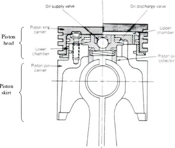
Generally, piston is one of the components in the internal combustion engine that is connected to a connecting rod to control its movement. The structure of the piston can be divided into two sections, which are the top section and the lower section as shown in Figure 3.1 in the following page. The top section is known as the crown or head while the lower section is called the skirt.
Figure 3.1 - Structure of Piston (Ferguson 1986, p. 46)
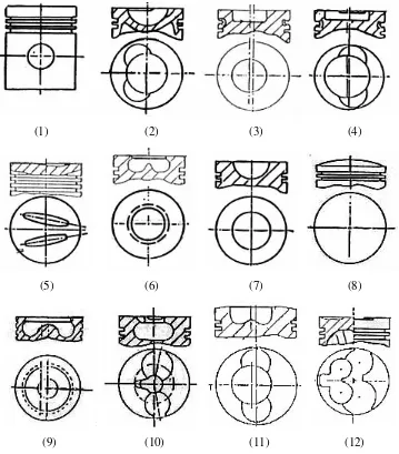
The shape of the piston crown depends on the design of the combustion chamber. There are various shapes such as concave, flat, cup, dome, hump and contour to promote turbulence in combustion or to control the combustion process (Yusof 2000, p.21). For example, a piston with an offset of a non-annular bowl is contoured to increase the spray plume length in order to avoid impingement. The shapes of the piston crown are shown in Figure 3.2 in the following page. However, to simplify the problem, a flat piston head (Figure 3.2(1)) is used for the design purpose.
Piston head
(1) (2) (3) (4)
(5) (6) (7) (8)
[image:41.595.118.477.112.521.2]
(9) (10) (11) (12)
Figure 3.2 - Various Shapes of Piston Crown (KVR BMC Pistons Limited 2004 <http://www.kvrbmc.com/shape_pis.htm>)
Next, the following section will explain on the mechanism of piston and its role in the engine. With a proper understanding on how the piston works in the engine, the design process will be made easier.
3.1.2 Mechanism of Piston in Internal Combustion Engine
Piston acts as an energy converter in an internal combustion engine. It is linked to a connecting rod and placed inside a cylinder, which is commonly known as combustion chamber. In any typical engine, the piston will transmit the gas pressure generated from the combustion process to the crank pin through the connecting rod.
From this mechanism, it converts the potential energy of the gases into kinetic energy that turns the crank shaft. Since, the piston moves up and down in the cylinder and rotates with the corresponding crank angle, its movement is said to be in a cyclic motion. Besides that, it also works as a movable gas-tight plug that seals the cylinder and to ensure that the combustion process operates in the cylinder itself (Ferguson 1986, p. 41).
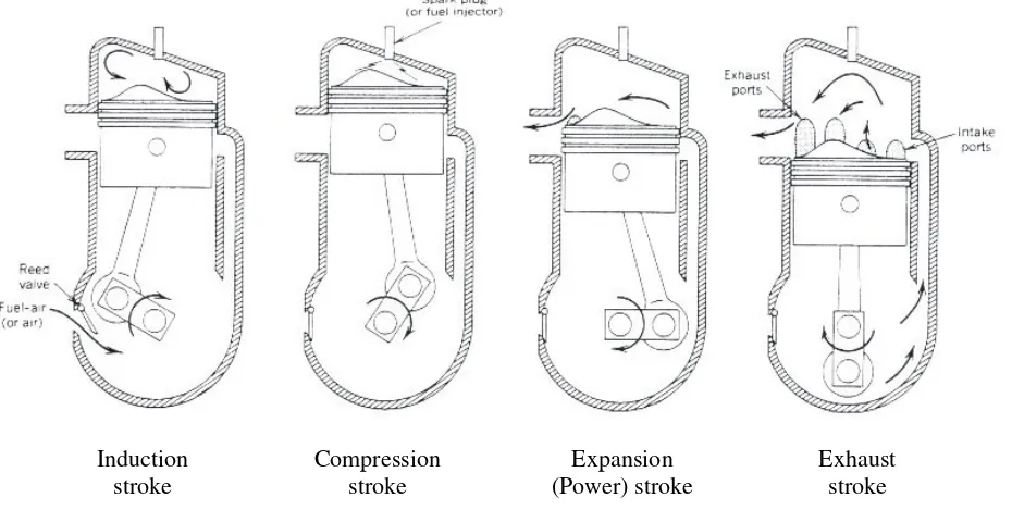
Figure 3.3 - Four-Stroke Cycle (Ferguson 1986, p. 42)
Each of the strokes is explained in more details as in the following:
• Intake stroke is the first stroke for the Diesel cycle, where the piston moves down to the bottom dead center (BDC). During this stroke, the inlet valve will open at the start of the stroke until it ends to let the air to flow into the combustion chamber while the exhaust valve is closed.
• Next, the piston will move up to the top dead center (TDC), which is also known as the compression stroke. Here, the air is compressed until just before the piston reaching the TDC, fuel is injected into the combustion chamber to ignite the combustion process through diffusion between fuel and air.
• Due to the high pressure gases compressed in the compression stroke, the piston is pushed down by the gases and forces the crank to rotate. Therefore, the piston will move from the TDC to the BDC again. This stroke powers the engine and thus it is known as the power stroke.
Induction
• For the fourth stroke, the piston will move up again to the TDC. As it approaches the TDC, the exhaust valve will open and allows the combustion products and the remaining burned gases to exit through it. Therefore, this stroke is known as exhaust stroke and the cycle will repeat again.
From the explanation above, the information will provide the basic knowledge for the design of piston in the combustion chamber. The most important part among the strokes mentioned above is the compression stroke, which is the time when the combustion will start to ignite at the TDC level. Next, the following section will explain on the effect of swirl and squish in the combustion chamber.
3.2 Swirl and Squish Action
Swirl is the rotational speed of the fluid within the cylinder about its axisthat has the same angular momentum as the actual flow when normalized by the engine speed (Ferguson 1986, p.287). In diesel engine, swirl is important because it promotes rapid mixing between the injected fuel and air inducted through the intake valve. Therefore, if swirl does not occur in diesel engine, the engine is said to be quiescent and the intensity of the fuel injected into the cylinder is instead relied upon to mix the fuel and air (Ferguson 1986, p.287).
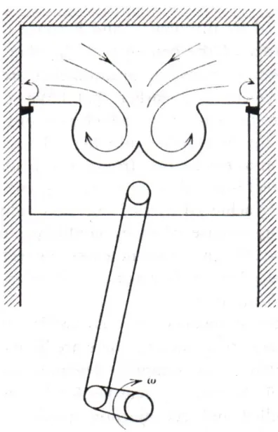
Figure 3.4 – Piston Cup for Swirl Amplification (Ferguson 1986, p. 297)
Since the original piston design for conventional diesel engine is a flat shape piston head, the swirl amplification still applies to the clearance volume of the piston when it is compressed adiabatically to the TDC. Although there is no bowl-in structure for the flat piston head, swirling of the mixture of fluid in the combustion chamber will still occur but might not be so significant compared to the bowl-in piston head.
By the way, swirl is proportional to the angular momentum but is inversely proportional to the moment of inertia (Ferguson 1986, p.298). However, the angular momentum within the cylinder is reduced or decayed by the fluid friction. It can only be increased during the intake stroke because it is convected in during that period. For other strokes, at any other time, the angular momentums will always decaying due to the fluid friction (Ferguson 1986, p.298).
Besides that, there is another phenomenon, which occurs in the clearance volume of the piston in the combustion chamber called the squish motion. It is a fluid motion that occurs toward the end of compression stroke when a portion of the piston surfaces and the cylinder head approach closely to each other (Ferguson 1986, p.287). It is also commonly associated with direct-injection engines and can be applied to the flat piston head design by inserting a plate between the engine block and the piston head.
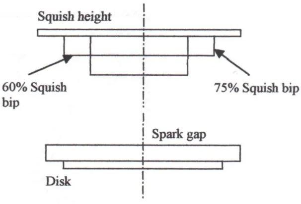
Usually, if the combustion chamber has a piston bowl located within the piston, a byproduct of the swirl amplification known as squish motion is used to amplify the swirl generated during the intake stroke (Ferguson 1986, p.299). Therefore, it is more significant to be seen in piston with bowl-in or groove geometry. For example, the squish motion that used to generate turbulence and swirl about a circumferential axis in piston bowl is shown in Figure 3.5 below.
[image:46.595.217.415.402.710.2]
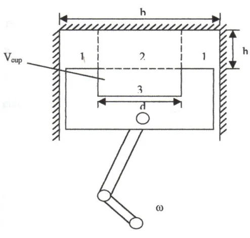
Besides that, the details on how the piston bowl can generate squish motion and swirl is illustrated in Figure 3.6. During the compression stroke, the density within the cylinder at any instant of time is almost uniform (Ferguson 1986, p.298). Therefore, the mass within zones 1, 2 and 3 is directly proportional to the volume in these zones at any time. When the piston moves upward to the TDC, zones 1 and 2 will get smaller while zone 3 remains the same. Hence, the mass in zones 1 and 2 must flow to zone 3.
Figure 3.6 – Generation of Squish and Swirl in a Control Volume of a Piston Bowl (Ferguson 1986, p. 298)
The velocity of gas flows between zones 1 and 2 is called squish velocity and zone 1 is known as squish zone (Ferguson 1986, p. 298). Since the density is uniform, the squish velocity depends only on the cylinder geometry and the rotational speed. When equation of continuity is applied to the control volume in Figure 3.6, it yields an expression for the ratio of squish velocity to instantaneous piston speed as follows:
V V dh
d b U
Us bowl
4
2 2 −
where
s
U = squish velocity
p
U =
dt dh
= instantaneous piston speed b= piston bore
d= piston stroke
h= clearance height or squish height Vbowl = Vcup = volume of piston bowl/cup
V = Vbowl b2h
4 π
+ = Total clearance volume
Next, in the following section, knocking effect will be discussed since it is a very important characteristic to determine the compression ratio in the engine. By understanding the effects of knocking, a better design for the piston in the combustion chamber can be made to prevent it.
3.3 Knocking Effect
Knocking occurs when the fuel self-ignited before reaching the TDC due to high pressure and high temperature inside the combustion chamber during the compression stroke. It is not preferred and should be avoided because it can cause failure to the piston and damage the whole cylinder block in a short period of time.
It is important to consider the knocking effect on the CNG-diesel engine and understand the factors that promote this phenomenon. There are a few factors that need to be considered such as the octane rating and cetane number of the fuel, the equivalence ratio, the ignition delay period, compression ratio and other operating parameters (CNG Engine Performance 1995, p.2).
chamber when operating in a higher compression ratio engine. Therefore, CNG can be used in a diesel engine with high compression ratio because it has a high octane rating of 130 (Yusaf et al. 1996a, p.21).
Cetane number is the ability of the fuel to self-ignite. Therefore, the cetane number and the octane rating are inversely correlated. Fuel with low cetane number tends to have higher ignition temperature and vice-versa. For CNG, the ignition temperature is about 900 K, which is capable to resist the high pressure and high temperature in the combustion chamber to avoid knocking (Compressed Natural Gas 11 March 2004 <http://www.mckenziecorp.com/dehydration.htm>).
However, practically CNG is unable to operate in high pressure and temperature during the compression stroke. As the CNG enters the combustion chamber, it will be compressed up to the design compression ratio of the engine. If the compression ratio is very high, then the CNG will be self-ignited due to high pressure inside the combustion chamber i.e. compression effect (Yusof 2000, p.55). Therefore, it is expected that the compression ratio for the engine needs to be reduced to accommodate CNG in the dual fuel engine system.
Besides that, another factor to prevent knocking is the ignition delay period. It is important to make sure that the fuel injection time is longer than the ignition delay time. If the ignition delay time is longer than the fuel injection time for a fixed operating condition for the engine, there would be more fuel injected into the combustion chamber and accumulated there before the fuel ignites (Yusof 2000, p.54). Thus, knocking will occur due to large amount of fuel accumulated inside the high pressure and high temperature combustion chamber when being compressed.
3.4 Piston Design
The conventional diesel engine with a compression ratio (CR) of 22.9:1 is modified to accommodate CNG in diesel engine. Since the original diesel engine operates under a high compression ratio, the conversion to a dual fuel engine system might promote knocking in the combustion chamber due to self-ignition characteristic of CNG.
Although CNG has a high octane rating of 130, it will still self ignite when operates in a high pressure combustion chamber due to compression effect of the compression stroke. Therefore, the compression ratio of the engine needs to be modified and reduced to obtain the optimum performance for the dual fuel CNG-diesel engine. The compression ratio can be reduced by three different methods, which are listed below (Yusaf et al. 1996, p.21).
• Modifying the piston groove or bowl • Modifying the length of the connecting rod • Insertion of plate onto the piston head
The first method is usually constructed by milling the piston head to create a recessed bowl shape. The size of the bowl depends on the size of the piston. It is usually suitable for large piston because small piston with recessed bowl can cause thermal stress to build up in the piston head and piston skirt. This will cause failure to the piston. The second method is to reduce the length of the connecting rod. However, this method is very costly and complicated to be constructed. Improper design will cause vibration and thermal stress to build up in the piston (Yusaf et al. 1996, p.21).
much simpler and does not require any complicated calculation. The calculation related to the implementation of plate on the piston head will be shown in Chapter 5.
When modifying the piston to reduce the compression ratio, it is important to make sure that the operation temperature and maximum pressure during the compression stroke are appropriate so that no pre-ignition occur in the combustion chamber. Besides that, the size and weight of the piston after modification should be the same as the original piston. This is to ensure that no vibration and inertia loading occur on the bearings in the piston. Lastly, the effects of the friction force between the piston and the cylinder block should be considered also (Yusaf et al. 1996, p.21).
In the next section, the details on the design criteria for the addition of plate onto the piston head to reduce the compression ratio are explained further.
3.5
Design Criteria for the Plate
The process to design a piston with an insertion of plate onto the piston head must follows a few considerations in order to accomplish the objectives of the project as mentioned earlier in Chapter 1. The considerations are listed below:
i. Role of piston in the internal combustion engine.
ii. Condition and parameters to be considered for the plate.
iii. The analytical methods used to study the combustion efficiency. iv. Piston materials.
v. Software used for the modeling and simulation.
After the objectives of the project are determined, the conditions and parameters that are used for plate to be inserted are considered. Those parameters are the distribution of temperature, pressure and stream function through the piston wall and combustion chamber wall under normal load condition. However, there might be other load conditions to be used during the analysis for improvement of the initial results obtained.
Next, the types of analysis to be used in the modeling of the piston are divided into two methods. There are the steady state analysis and the transient analysis. The first one will be used when the model needs to consider all the mechanical parameters such as power output, torque, engine speed, mechanical load and thermal load. This analysis is further executed by following the Rapid Analysis of Products by Integrated Engine Routine (RAPIER) used in the FLUENT software (Yusof 2000, p.34).
This routine consists of three steps:
i. The proposed piston needs to consider the objectives of the design, the criteria to accomplish the objectives, constraints encountered, appropriate recommendations and the usage of standard CAD application.
ii. Application of loads to test the piston. For examples, the firing condition and non-firing condition. Firing condition is the loads exerted to the TDC by the piston motion and its stresses, temperature and displacement.
iii. Sub-modeling by continuously repeating the modeling process for any minor changes to improve the piston design.
i. No load steady state condition.
ii. Linear ramp from no load condition to full load condition until the temperature stabilized to detect a transient response.
iii. Full load steady state condition.
iv. Linear ramp from full load condition to no load condition until the temperature stabilized to detect a transient response.
After executing tasks from part (i) to part (iii), selection of the most suitable material is necessary to make a piston. The criteria for a good quality of piston should have high quality in terms of strength, durability, thermal conductivity and wear resistance as well as lightness in weight. Therefore, aluminium is chosen as the most suitable material for the piston in this project.
Lastly, the computational fluid dynamics softwares to be used are GAMBIT version 2.1 and FLUENT version 6.1 for modeling and simulation work respectively. Besides these two softwares, there are other softwares such as ANSYS, CFD-ACE, Pro-Engineer and Solidworks to execute the tasks. However, these two softwares are chosen due to their compatibility and the excellence function of FLUENT in analyzing flows of fluid in various conditions such as combustion, reacting and non-reacting flows, turbulence model and etc.
It is important to follow the steps of the design process as mentioned above for accuracy and effectiveness of the product designed. These design steps can be proven by the accomplishment of piston produced using these steps such as the conventional standard piston, aluminum gallery piston, reentrant bowl piston, fiber-reinforced piston and the fiber-reinforced aluminum gallery piston (Yusof 2000, p. 36).
CHAPTER IV
COMPUTATIONAL FLUID DYNAMICS (CFD)
4.1 Introduction
Computational fluid dynamics (CFD) is a technology that is used to analyze the dynamics of anything that can flow regardless in liquid or gaseous state. It is a software tool that can model or simulate a flow or phenomena of any system or device under analysis.
CFD is computed using a set of partial differential equations to predict the flow behavior. Besides that, it is also used for analyzing heat transfer model, mass flow rate, phase change such as solidification, chemical reaction such as combustion, turbulence model, mechanical movement such as rotating shaft, deformation of solid structure and many more (FLUENT Manual – Introduction 2004) .
The procedure for the CFD analysis in FLUENT follows the simple steps below:
i. The model used for the analysis is drawn, meshed and the boundary layers are determined. This is done using the GAMBIT software, which is the compatible modeling software for FLUENT. All the files for the geometry and meshing of the model are saved as mesh or grid file.
ii. Next, in FLUENT, the saved mesh or grid file of the model is read, checked and scaled for the required working unit.
iii. The model is defined for the type of solver and boundary conditions to be used. The model is defined according to the type of analysis required in the research project.
iv. The model is solved by setting the required parameters in the solution panel and then iterated for convergence.
v. Results can be obtained from the graphic display and report in FLUENT. Results can be displayed in terms of contour, velocity vector, particle track and path line. Any calculation required can be performed in FLUENT also.
vi. Finally, the results and all the data can be saved for future references by writing the files.
4.2 Capability of FLUENT Solver
This software has various modeling capabilities that can be used in numerous kinds of analysis and application. Among its capabilities are listed below (FLUENT Manual – Program Capabilities 2004):
• Flows in 2D or 3D geometries are using unstructured solution-adaptive triangular/tetrahedral, quadrilateral/hexahedral, or mixed (hybrid) grids that include prisms (wedges) or pyramids.
• Incompressible or compressible flows.
• Steady-state or transient analysis.
• Inviscid, laminar, and turbulent flows.
• Newtonian or non-Newtonian flow.
• Convective heat transfer, including natural or forced convection.
• Coupled conduction/convective heat transfer.
• Radiation heat transfer.
• Inertial (stationary) or non-inertial (rotating) reference frame models.
• Multiple moving reference frames, including sliding mesh interfaces and mixing planes for rotor/stator interaction modeling.
• Chemical species mixing and reaction, including combustion sub-models and surface deposition reaction models.
• Lagrangian trajectory calculations for a dispersed phase of particles/droplets/bubbles, including coupling with the continuous phase.
• Flow through porous media.
• One-dimensional fan/heat-exchanger performance models.
• Two-phase flows, including cavitation.
• Free-surface flows with complex surface shapes.
All the capabilities mentioned above are useful in providing a better approach for the analysis in applications such as process equipment, aerospace and turbo machinery, automobile, heat exchanger power generation in oil/gas industry and material processing. Therefore, with the availability of such capabilities, the analysis for the purpose of this research project can be carried out in a more accurate and user-friendly way.
4.3 Governing Equations
The CFD methodology in FLUENT is using partial differential equations of flow variables to calculate and to simulate numerous kinds of analysis concerning the fluid flow. Among the flow variables that are commonly used in analysis are mass, momentum, energy, species concentration, quantities of turbulence and mixture fractions. Therefore, the governing equations to be used in this analysis are the conservation of mass, momentum, energy and turbulent equations.
4.3.1 Mass Conservation Equation
m u x
t j j =
+
)
( (4.1)
where
= fluid density
j
u = the jth Cartesian component of the instantaneous velocity m = the rate of mass of the object generated in the system
This equation is valid for the incompressible and compressible flows. Moreover, the rate of mass generated in the system, m can be defined as the mass added to the continuous phase from the dispersed second phase such as the vaporization of liquid droplets and any other user-defined sources.
4.3.2 Momentum Conservation Equation
The conservation of momentum in i direction for an inertial reference frame can be explained as (FLUENT Manual – Momentum Conservation Equations 2004):
i i j ij i j i j
i x x g F
p u
u x u
t + =− + + +
) ( ) ( (4.2) where
= fluid density
ui &uj = the ith and jth Cartesian components of the instantaneous
velocity p = static pressure
ij = stress tensor
gi = gravitational body force i
F = external body force from interaction with the dispersed phase in i direction
ij k k i j