This is a repository copy of
Multiplier-less low-delay FIR and IIR wavelet filter banks with
SOPOT coefficients
.
White Rose Research Online URL for this paper:
http://eprints.whiterose.ac.uk/93753/
Version: Accepted Version
Proceedings Paper:
Liu, W., Chan, S.C. and Ho, K.L. (2000) Multiplier-less low-delay FIR and IIR wavelet filter
banks with SOPOT coefficients. In: 2000 10th European Signal Processing Conference. ,
4-8 Sept. 2000, Tampere, Finland. IEEE , pp. 1-4. ISBN 978-952-1504-43-3
[email protected]
https://eprints.whiterose.ac.uk/
Reuse
Unless indicated otherwise, fulltext items are protected by copyright with all rights reserved. The copyright
exception in section 29 of the Copyright, Designs and Patents Act 1988 allows the making of a single copy
solely for the purpose of non-commercial research or private study within the limits of fair dealing. The
publisher or other rights-holder may allow further reproduction and re-use of this version - refer to the White
Rose Research Online record for this item. Where records identify the publisher as the copyright holder,
users can verify any specific terms of use on the publisher’s website.
Takedown
If you consider content in White Rose Research Online to be in breach of UK law, please notify us by
MULTIPLIER-LESS LOW-DELAY FIR AND IIR WAVELET FILTER BANKS WITH SOPOT COEFFICIENTS
W. Liu, S. C. Chan and K. L. Ho
Department of Electrical and Electronic Engineering The University of Hong Kong, Pokfulam Road, Hong Kong.
ABSTRACT
In this paper, a new family of multiplier-less two-channel low-delay wavelet filter banks using the PR structure in [3] and the SOPOT(sum-of-powers-of-two) representation is proposed. In particular, the functions α(z) and β(z) in the structure are chosen as nonlinear-phase FIR and IIR filters, and the design of such multiplier-less filter banks is performed using the genetic algorithm. The proposed design method is very simple to use, and is sufficiently general to construct low-delay wavelet bases with flexible length, delay, and number of zero at π (or 0) in their analysis filters. Several design examples are given to demonstrate the usefulness of the proposed method.
I. INTRODUCTION
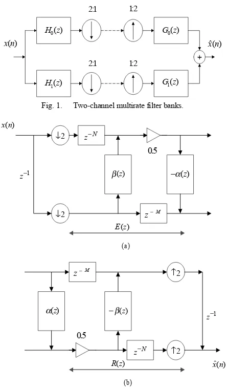
Perfect reconstruction (PR) multirate fiIter banks have important applications in signal analysis, signal coding and the design of wavelet bases. Figure 1 shows the block diagram of two-channel maximally decimated filter banks. In [3], a new structure for two-channel perfect reconstruction FIR/IIR filter banks is proposed. It is parameterized by two functions α(z) and
) (z
β , which can be chosen as linear-phase FIR or all-pass
functions to realize new classes of FIR and IIR filter banks with very low design and implementation complexities and good frequency characteristic. In [3], the case of using identical α(z) and )β(z with delay parameter M =2N−1 (see Fig. 2) is studied to obtain linear-phase FIR or passband linear-phase IIR filter banks. Furthermore, by imposing the K-regularity condition, linear-phase FIR and passband linear-phase IIR wavelet bases can readily be obtained.
In this paper, we shall investigate the construction of a class of wavelet bases associated with these filter banks when α(z) and
) (z
β are nonphase FIR or IIR functions. As the linear-phase requirement is relaxed, the lengths of α(z) and β(z) are no longer restricted by the delay parameters of the system. Therefore, higher stopband attenuation can still be achieved at low system delay. By representing each coefficient as sum of powers of two (SOPOT), multiplier-less filter banks and wavelet bases can be obtained. The design of such multiplier-less filter banks is performed using the genetic algorithm (GA). The proposed design method is very simple to use, and is sufficiently general to construct low-delay wavelet bases with flexible length, delay, and number of zero at π (or 0) in their analysis filters. Several design examples are given to demonstrate the usefulness of the proposed method. Design results show that GA is capable of finding very good filter banks and wavelets with very low implementation complexity. The average number of terms used per coefficient in the design examples ranges from 2.3 to 2.9, i.e. each coefficient multiplication can efficiently be implemented with 1.3 to 1.9 additions. The paper is organized as follows: Section II is a summary of the theory of two-channel filter banks and related wavelet bases. The structure proposed in [3] and the basic idea behind the proposed low-delay wavelet bases will also be described. Section III is devoted to the proposed design method. In section IV several design examples will be given to demonstrate the usefulness of the proposed algorithm. Finally, conclusions are drawn in Section V.
II. TWO-CHANNEL STRUCTURAL PR FILTER BANKS AND WAVELET BASES
Fig. 1 shows the structure of a two-channel critically decimated multirate filter bank. It can be shown that [1] the reconstructed signal, )Y(z , is given by
) ( ) ( ) ( ) ( )
(z T z X z Az X z
Y = + − ,
where
[
( ) ( ) ( ) ( )]
2 1 )
(z H0 zG0 z H1 zG1 z
T = + ,
[
( ) ( ) ( ) ( )]
2 1 )
(z H0 zG0 z H1 zG1 z
A = − + − − . (2-1)
The aliasing term, A(z), can be canceled if the analysis and synthesis filters are chosen as follows
) ( )
( 1
0 z H z
G =− − , G1(z)=H0(−z). (2-2)
Combining (2-1) and (2-2), one gets the following PR condition in )
( 0 z
H and H1(z)
[
( ) ( ) ( ) ( )]
02 1 )
( 0 1 0 1
n
cz z H z H z H z H z
T = − − − = − (2-3)
where
n
0 is an integer andc
is a non-zero constant.In [3], a new class of two-channel structurally-PR filterbanks and wavelet bases are proposed (Fig.2). The expressions for the analysis filters are given by:
2 )) ( (
) (
2 1 2
0
z z z z H
N −β − +
= , 0 2 1
2
1( ) ( ) ( )
− −
+ −
= M
z z H z z
H α . (2-4)
It can be seen from (2-4) that (2-3) is satisfied for any choices of )
(z
α and β(z). Therefore, FIR and IIR filter banks can readily be realized by choosing α(z) and β(z) as polynomials or rational functions. In [3], the case of using identical α(z) and β(z) is studied with the delay parameter M chosen as 2N−1. New classes of FIR and IIR filter banks were obtained by choosing
) (z
β and α(z) as Type-II linear-phase functions and all-pass functions, respectively. The design of β(z) (and α(z)) can be accomplished by noting that H0(z) (and H1(z)) will become
ideal lowpass (and highpass) filter if β(z)(and )α(z ) has the following magnitude and phase responses
1 )
( 2ω =
β j
e ∀ω (2-5a)
[
]
⎩ ⎨ ⎧
∈ ±
+ −
∈ +
− = ∠
]. , 2 / ( )
1 2 (
; 2 / , 0 )
1 2 ( )
( 2
π π ω π
ω
π ω ω
β ω
for N
for N
ej
(2-5b)
Moreover, by imposing zeros at ω =π for H0(z) and
0
=
ω for H1(z), wavelet bases can be constructed from the resulted filter banks. In fact, the theory of wavelet is closely related to that of multirate filter banks. It have been shown that discrete dyadic wavelets can be obtained from two-channel PR filter banks with added regularity condition [4,5]. For biorthogonal dyadic wavelet bases, H0(z)and G0(z) should have
0
K (or 0
~
K ) zeros at z=−1(the K-regularity condition), and
) ( 1 z
H and G1(z) should also have at least one zero at z=1 [5]:
0 ) (
1
0 =
− =
z k k
dz z H d
,k=0,1,....,K0−1; 0
) (
1
0 =
− =
z k k
dz z G d
,
1 ~ ,...., 1 ,
0 0−
= K
0 ) 1 ( ) 1 ( 1
1 =G =
H . (2-7)
The delay of the system proposed in [3] can be shown to be
1 2 2
0 = N+ M+
n . (2-8)
If )α(z and β(z) are identical and are chosen as Type-II linear-phase functions or all-pass functions, then the system delay will be predetermined by the length of α(z) or β(z). The only way to reduce the system delay in some low-delay applications is to reduce the length of the filters, which will unavoidably reduce the stopband attenuation of the filter banks. To overcome this problem, nonlinear-phase FIR or IIR functions have to be used for
) (z
α and β(z) so that more flexibility are available in choosing the filter length and hence their stopband attenuation. The system delay is still given by (2-8). But the lengths of α(z) and β(z) are no longer limited by the values of M and N. In the following section, we shall investigate the construction of a class of wavelet bases associated with this family of low-delay filter banks.
III. THE PROPOSED DESIGN METHODS
As mentioned earlier, α(z) and β(z) considered in this paper are nonlinear-phase. We aim to design the multiplier-less low-delay wavelet filter banks by imposing a given number of zeros at z=−1 for H0(z), and z=0 for H1(z). Since the filter
bank is still PR if the coefficients of α(z) and β(z) are quantized to other values, it is possible to reduce its complexity by expressing them in sum-of-powers-of-two coefficients. By so doing, each coefficient multiplication can be efficiently performed by simiple additions and shifts. A number of methods have been proposed for designing FIR filters with SOPOT coefficients. A classical work is the integer programming method proposed by Lim [9]. Other heuristic methods such as stimulated annealing [10] and genetic algorithm [11] have also been proposed as alternatives to the problem. These heuristic techniques are in general very easy to apply, and is able to yield reasonably good solution even when the objective function is non-smooth. In [7,12], the genetic algorithm (GA) is used to design SOPOT multiplier-less 2-channel orthogonal and biorthogonal linear-phase filter banks using respectively the structure in [2] and the transformation method.
In this paper, GA is also employed to search for the SOPOT coefficients of α(z) and β(z) in the proposed multiplier-less low-delay wavelet filter banks. Each coefficient of α(z) and
) (z
β is represented as follows:
∑
=
= n k
p k b k a n h 1 2 . )
( , ak∈{−1,1}bk∈{l,...,1,0,−1,...,−l}. (3-1)
“ l” is a positive integer and its value determines the range of coefficients. pn is the number of terms of the n-th coefficient.
Normally, pn is limited to a small number, and the multiplication
of such SOPOT coefficient can be implemented with simple shifts and additions. In this work, each coefficient is allowed to have different number of terms. The objective function we minimize is
|| ) ( ~ | | ) ( || max )
(Hk Hk ω Hk ω
E = − , ]k∈{0,1},ω∈[0,π , (3-2)
where H~k(ω) is the desired frequency response of the k-th channel. To obtain the corresponding wavelet bases, we need to incorporate the K-regularity conditions in (2-6) and (2-7). If we substitute (2-4) into (2-6) and (2-7), one gets a set of equations that have to be satisfied. The problem is a constrained nonlinear optimization, which cannot be easily handled by conventional genetic algorithm. Fortunately, it is found that these conditions can be used to eliminate some of the design variables, and it leads to an unconstrained optimization with fewer variables. From the GA point of view, the resulting problem is surprisingly easier to solve than that without the K-regularity constraints. In other words, it is easier to design the wavelet bases than to design the corresponding filter banks, using GA.
Next, we give several examples to illustrate the proposed method.
IV. DESIGN EXAMPLES
1. Low-Delay FIR Wavelet Bases
In this case, both α(z) and β(z) are nonlinear phase FIR filters with length Lα and Lβ. Let’s express the coefficients of α(z)
and )β(z as α(0),α(1)...and )β(0 ,β(1)..., respectively.
Using ( ) 0
1 0 = − = z k k dz z H d
, we get for k=0 the following
1 ) (z z=1=
β or equivalently
∑
− = = 1 0 1 ) ( β β L i
i . (4-1a)
And for k=1,2,...
∑
− = − = − − − − − = − − ⋅ ⋅ ⋅ − − + + − − ⋅ ⋅ ⋅ − − − 1 0 1 1 2 2 1 | ) ( ) 2 ( ) 1 2 ( ) 1 2 ( ) 1 2 )( 2 ( β β L i z k i k N z i k i i z k N N N . (4-1b)On the other, from ( ) 0
1 0 = − = z k k dz z G d
, we get ( ) 0
1 1 = = z k k dz z H d
, and for
k=0, the following
1 ) (z z=1=
α , or
∑
− = = 1 0 1 ) ( α α L i
i . (4-1c)
And for k=1,
( ) ( ) 2 ( ) ( ) ( 2 1) | 1 0
2 2 0 2 ' ' 0
2 − + − − =
− − − z=
M z M z H z z z H z α
α . (4-1d)
Similar conditions can be obtained if we keep on differentiating the equation for k=2,3, .., and so on.
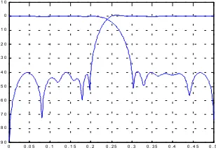
Example 4.1:. The specifications are: K0=K~0=1, M=8, N=3,
cutoff frequencies: ω1=0.4π, ω2=0.6π, stopband attenuation :
39dB. α(z) andβ(z) are nonlinear-phase FIR filters with lengths Lα=14, Lβ=12, and delays 5.5, 2.5, respectively. The
overall system delay is 23. The regularity constraints can be
expressed as: β(0)=1−β(1) −β(11),
) 13 ( ) 1 ( 1 ) 0
( α α
α = − ⋅⋅⋅⋅⋅⋅− , thus we have two parameters less to
optimize than in the corresponding filterbanks case. The average number of terms used per coefficient is 2.3.The coefficients of the SOPOT wavelet filter banks and its frequency responses are summarized in Table 1 and Figure 3, respectively.
Example 4.2:. The specifications are: K0=K~0=3, M=5, N=2,
α
L =10, Lβ=8; cutoff frequencies: 0.38π, 0.62π; stopband
attenuation: 30dB; delays of α(z),β(z) and the system are 3.5, 1.5, and 15, respectively.
By solving the corresponding equations in (4-1), one gets:
8 / )) 7 ( 168 ) 6 ( 120 ) 5 ( 80 ) 4 ( 48 ) 3 ( 24 3 ( ) 2 ( β β β β β β − − − − − = (4-2a) 2 / )) 7 ( 14 ) 6 ( 12 ) 5 ( 10 ) 4 ( 8 ) 3 ( 6 ) 2 ( 4 3 ( ) 1 ( β α β β β β β − − − − − − = (4-2b) ) 7 ( ) 2 ( ) 1 ( 1 ) 0
( β β β
β = − − ⋅⋅⋅⋅⋅⋅− ; (4-2c)
) 9 ( 36 ) 8 ( 28 ) 7 ( 21 ) 6 ( 15 ) 5 ( 10 ) 4 ( 6 ) 3 ( 3 8 / 35 ) 2 ( α α α α α α α α − − − − − − − = (4-2d) ) 9 ( 9 ) 4 ( 4 ) 3 ( 3 ) 2 ( 2 2 / 7 ) 1
( α α α α
α = − − − ⋅⋅⋅⋅⋅⋅− (4-2e)
) 9 ( ) 2 ( ) 1 ( 1 ) 0
( α α α
α = − − ⋅⋅⋅⋅⋅⋅− . (4-2f)
By eliminating these variables, we only have 8+10-6=12 free parameters to optimize, 6 less than the original filter banks. The
average number of terms used per coefficient is 2.9. The
2. Low-Delay IIR Wavelet Bases.
In general, both α(z) and β(z) can be IIR filters. In the design process, however, we find that its performance/complexity trade-off is not satisfactory. In fact, we find that it is more efficient to choose one of α(z) and β(z)to be a nonlinear-phase FIR filter and the other as an IIR filter. Much better performance can be achieved with similar implementation complexity.
Example 4.3:. The specifications are: K0=K~0=1, M=5, N=2;
stopband attenuation: 30dB; cutoff frequencies: ω1=0.4π,
π
ω2=0.6 . The overall system delay is 15. β(z) is an IIR filter
with delay 1.5 and is given by
7 3 5 2 4 1 3
6 3 2 2 1 1 0
) 1
(
) 1
( ) (
c z c z c z c
c z c z c z c
z − − −
− − −
+ + +
+ + + =
β .
Because ( ) 1
1=
=
z
z
β , we have c6=1+c3+c4+c5 and
2 1 0
7 1 c c c
c = + + + . α(z) is a nonlinear-phase FIR filter with
length Lα=10 and delay 3.5. The average number of terms used per coefficient is 2.8. The coefficients of the SOPOT wavelet filter banks and its frequency responses are summarized in Table 3 and Figure 5, respectively.
Example 4.4: The specifications are: K0=3,K~0=1, M=4, N=2;
stopband attenuation: 36dB; cutoff frequencies are: ω1=0.34π,
π
ω2=0.66 . The overall system delay is 13. β(z) is a FIR filter with length Lβ=8 and delay 1.5. The constraints are the same as
equations (4-2a), (4-2b), and (4-2c). α(z) is an all-pass filter with
order 3 and delay 2.5:
∑
∑
= − =
− −
= 3
0 3
0 3 )
(
k k k k
k k
z a
z a z
α , which automatically
fulfills the requirement ( ) 1
1=
=
z
z
α . The reason for the choice is
to demonstrate the good performance/complexity tradeoff of this type of hybrid filter banks. It will be seen later that the performance of using the all-pass filter is very good and its complexity is extremely low. Higher stopband attenuation can of course be achieved by using nonlinear-phase FIR and IIR functions with longer lengths at the expense of higher implementation complexity. The coefficients of the SOPOT wavelet filter banks and its frequency responses are summarized in Table 4 and Figure 6, respectively. . The average number of terms used per coefficient is 2.4.
V. CONCLUSION
A new family of multiplier-less two-channel low-delay
wavelet filter banks using the PR structure in [3] and the SOPOT representation is presented. The functions α(z) and β(z) in the structure are chosen as nonlinear-phase FIR and IIR filters, and the design of such multiplier-less filter banks is performed using the genetic algorithm. It was found that GA is able to find very good solution to this problem. The proposed design method is very simple to apply, and is sufficiently general to construct low-delay wavelet bases with flexible length, low-delay, and number of zero at π (or 0) in their analysis filters. Several design examples are given to demonstrate the usefulness of the proposed method.
REFERENCES
[1] P. P. Vaidyanathan, Multirate systems and filter banks. Englewood Cliffs, NJ: Prentice Hall, 1992.
[2] C.Sidney Burrus, Ramesh A.Gopinath, and Haitao Guo. “Introduction to wavelets and wavelet transforms”. Prentice Hall, 1998.
[3] S. M. Phoong, C. W. Kim and P. P. Vaidyanathan, “A new class of two-channel biothogonal filter banks and wavelet bases”, IEEE Trans. SP, Vol.43, No. 3, pp.649-664, March 1995.
[4] I. Daubechies, “ Orthonormal bases of compactly supported wavelets,” Commun. Pure Appl. Math., Nov. 1988, Vol. 41, pp. 909-996
[5] A. Cohen, I. Daubechies and J. Feauveau, “ Biorthogonal bases of compactly supported wavelets,” Comm. Pure Applied. Math. Vol. 45, pp. 485-560, 1992.
[6] K.S. Tang, K.F.Man, S.Kwong and Q.He, “Genetic
algorithms and their applications”, IEEE Signal Processing Magazine, pp.22-37, Nov 1996.
[7] S. Sriranganathan, D. R. Bull, D. W. Redmill, “The design of Low Complexity Two-Channel Lattice-Structure Perfect-Reconstruction Filter Banks Using Genetic Algorithm”. Proc. of ISCAS '97., vol.4, pp.2393-2396, June 1997. [8] Al-Adnani, A.; Chapman, R.; Durrani, T.S., “Time-domain
design of low delay wavelet transforms”, Electronics Letters, Vol. 29. No. 9, pp. 2177 – 217, Dec. 1993
[9] Y. C. Lim, S. R. Parker, “FIR filter design over a discrete
power-of-two coefficients space,” IEEE Trans. Acoust.
Speech, Signal Processing, vol. ASSP-31, pp. 583-591, June 1983.
[10] N. Benvenuto, M. Marchesi, A. Uncini, “Applications of simulated annealing for the design of special digital filters,” IEEE Trans. on Signal Processing, Vol. 40, No. 2, pp. 33-332, Feb. 1992.
[11] D. W. Redmill and D. R. Bull, “Automated design of low complexity FIR filters,” Proc. IEEE ISCAS’98, vol. 5, pp. 429-432, 1998.
[12] D. W. Redmill, D. R. Bull, and R. R. Martin, “Design of multiplier free linear phase perfect reconstruction filter banks using transformations and genetic algorithms, Sixth International Conference on Image Processing and Its Applications, Vol. 2, pp. 766-770, 1997.
x n( ) x n( )
H z0( )
H z1( )
G z0( )
G z1( ) 21:
21:
12:
[image:4.612.314.560.25.711.2]12: ++
Fig. 1. Two-channel multirate filter banks.
↓2
↓2 z−N
z−M
β( )z −α( )z
z−M
z−N −β( )z α( )z
↑2
↑2 x n( )
z−1
z−1
( ) x n E z( )
R z( )
(b) (a)
05.
05.
[image:4.612.330.552.328.708.2]0 0 . 0 5 0 . 1 0 . 1 5 0 . 2 0 . 2 5 0 . 3 0 . 3 5 0 . 4 0 . 4 5 0 . 5 -9 0
-8 0 -7 0 -6 0 -5 0 -4 0 -3 0 -2 0 -1 0 0 1 0
Fig. 3. Frequency responses(dB) of analysis filters in Example 4.1.
0 0 . 0 5 0 . 1 0 . 1 5 0 . 2 0 . 2 5 0 . 3 0 . 3 5 0 . 4 0 . 4 5 0 . 5 -9 0
-8 0 -7 0 -6 0 -5 0 -4 0 -3 0 -2 0 -1 0 0 1 0
(a)
0 0 .1 0 .2 0 .3 0 .4 0 .5 0 .6 0 .7 0 .8 0 .9 1 -2
0 2 4 6x 1 0
-5
S c a ling F u n c t io n
0 0 .1 0 .2 0 .3 0 .4 0 .5 0 .6 0 .7 0 .8 0 .9 1 -2 .5
-2 -1 .5 -1 -0 .5 0 0 .5 1 1 .5 2 2 .5 x 1 0-5
W ave let F u n c tio n
(b)
Fig. 4. Wavelet filter banks in Example 4.2: (a) Frequency responses(dB) of analysis filters, (b) scaling and wavelet functions (K=3,K~=3).
0 0 . 0 5 0 . 1 0 . 1 5 0 . 2 0 . 2 5 0 . 3 0 . 3 5 0 . 4 0 . 4 5 0 . 5 -6 0
-5 0 -4 0 -3 0 -2 0 -1 0 0 1 0
Fig. 5. . Frequency responses(dB) of analysis filters in Example 4.3.
0 0 . 0 5 0 . 1 0 . 1 5 0 . 2 0 . 2 5 0 . 3 0 . 3 5 0 . 4 0 . 4 5 0 . 5 -9 0
-8 0 -7 0 -6 0 -5 0 -4 0 -3 0 -2 0 -1 0 0 1 0
(a)
0 0.1 0.2 0.3 0.4 0.5 0.6 0.7 0.8 0.9 1 -2
0 2 4 6x 10
-5
S c aling F unc tion
0 0.1 0.2 0.3 0.4 0.5 0.6 0.7 0.8 0.9 1 -8
-6 -4 -2 0 2 4 6 8x 10
-5
W avelet F unc tion
[image:5.612.96.250.33.140.2](b)
Fig. 6. Wavelet filter banks in Example 4.4. (a) Frequency responses(dB) of analysis filters, (b) scaling and wavelet functions (K=3,K~=1).
I α(i) β(i)
0 7 9
2 2− − −
− 5 7 8
2 2 2− + − + −
1 5 8 10
2 2
2− − − − − 3
2−
−
2 4 7 9
2 2 2− + − − −
− 1 4 6
2 2 2− + − − −
3 4 5 9
2 2
2− + − + − 1 2 5
2 2 2− + − − −
4 −2−2+2−4 2 5
2 2− − −
−
5 1 3 8
2 2
2− + − + − 2 4 7
2 2 2− − − − −
6 1 3 7
2 2
2− + − + − 3 8
2 2− − −
− 7 −2−3−2−4−2−7 2−4+2−6+2−7
8 2−3−2−6−2−7 −2−4
9 4 8
2 2− + −
− 5 8
2 2− + −
10 5
2− 6 8
2 2− − −
−
11 6 9
2 2− + −
− 7
2−
12 2−7
13 9 10
2 2− − −
−
Table 1.
i α(i) β(i)
0 6 8
2 2− − −
− 4 6 9
2 2 2− − − − −
−
1 3 5 7 9
2 2 2
2− − − − − − − 2−1+2−5+2−7+2−9
2 −2−3−2−5−2−6−2−8 2−1+2−2−2−6−2−9
3 2−1+2−4+2−5 2 5 7 9
2 2 2
2− − − − − − −
−
4 1 3 6
2 2
2− + − + − 3 5
2 2− + − 5 −2−3−2−4−2−7 −2−3+2−6+2−8
6 2−3−2−6 4 8
2 2− − −
7 4 6 8
2 2 2− + − − −
− −2−6+2−8
8 6 7
2 2− + −
9 −2−7−2−9
Table 2.
i α(i) ci
0 −2−4+2−7 −22+2−1−2−3
1 3 6
2
2− − − −23−2−1+2−4
2 −2−3−2−4+2−6 0 1 3 5
2 2 2
2 − − − − − −
−
3 2−1+2−3−2−7 1 3 5 6
2 2 2
2− + − + − + −
4 1 3 7 9
2 2 2
2− + − + − + − 0
5 2 4 7 8
2 2 2
2− + − − − − −
− 0
6 3 5 8 9
2 2 2
2− − − + − + − 21−2−2 −2−4−2−6
7 −2−4+2−7 −23 −22 −2−1 −2−2 +2−5
8 5
2−
9 7 8
2 2− − −
−
Table 3.
i β(i) ai
0 4 7 9
2 2 2− − − + −
− 0
2
1 1 6 9
2 2
2− + − + − 1 5 9
2 2 2− − − + −
2 1 2 6 8
2 2 2
2− + − − − + − 4 5 9 2 2 2− − − + −
−
3 2 5
2 2− − −
− 5 9
2 2− − −
4 3 6
2 2− + −
5 −2−4−2−7 6 2−5−2−7+2−9
7 9
2−
−