Abstract: Error free transformation is a major issue in present Electronic circuits. Fixed data transmission from sender to receiver occurring greater issue, i.e. errors in information of data transmission from transmitter to receiver. In the digital communication systems, digital code may be distorted during transmission, which can show to the inaccurate information response of the receiver. Here Error correction codes used to protect the information In memories and logic registers in electronic circuits. Hamming codes are one of the best errors, correcting code either, even parity or odd parity check method. In this project Hamming code algorithm is used for Errors detection and Error rectification. The Hamming codes will be implemented in Xilinx & Cadence, At the receiver information is recovered to get original 15 bit information signal data. In which 15bit information data will be transmitted with 4 bit redundant two Error value bits. At the receiver is recovered to get 11 bit data (input data).
Index Terms: Hamming code, Error detection, Error correction, Cadence tool.
I.INTRODUCTION
In digital communication, errors are introduced during the transmittal of data from sender to receiver due to interference or noise. Fault is a circumstance when the output information does not correspond with the input information that means “0” bit invert to “1” or “1” bit invert to “0”. These erroneous beliefs can become a severe problem for achieving accuracy and operation of the system [1]. Thus, the reliability of information transmittal is needed to be amended. To improve the reliability, it is indispensable to find and even off the mistake. Hence, we have to employ some kind. Error perception and error rectification codes. This type of codes, one or two than one other number is appended to bits at the time of sending the information. These additional numbers are called a parity bit that bits helps to find the faults. A parity bit or a check number added to the remainder of a binary code that shows whether the number of bits input data is even or uneven. The parity may be either even or uneven. Even parity is the number of one‟s in the given input data the parity bit shows (2, 4, 6) bit positions. Odd Parity is the number of 1's in the given input data The bit should be shown (1, 3, 5) bit positions. The data bits along with the parity bit forms a
Revised Manuscript Received on June 05, 2019
M.Narasimha Rao, Department of ECE, GMR Institute of Technology, GMR Nagar, Rajam, Srikakulam District, Andhra Pradesh, India.
Dr.T.Prabhakar Department of ECE, GMR Institute of Technology, GMR Nagar, Rajam, Srikakulam District, Andhra Pradesh, India
K.Satya Kiran Department of ECE, GMR Institute of Technology, GMR Nagar, Rajam, Srikakulam District, Andhra Pradesh, India
code word. Codes Which allow only error detection are called Error detection codes and are used to detect an error occurred during TX of the message. A simple example of error detection code is parity check method and both codes are error detection and error rectification also called error recognition and correction codes. In error rectification codes, parity check has a childlike mode to detect error location bits.At one time the corrupted bit is located, At one time the corrupted bit is present, its value is a range (from 0 to 1 or 1 to 0). There are dissimilar cases of error controlling codes such as parity checking, checksum error detection, CRC. Comparing with other error identification codes, hamming code is one of the best methods for error detection as well as error rectification
II. PROCEDUREFORHAMMINGCODES
A. Hamming codes
Hamming code not just provides the detection of a bit error, but also identifies detect a double bit error. The number of numbers assigned as „m‟ then the number of parity bits ‟P‟ is determined by the following relationship
2P ≥ P + m + 1 Here m= number of message bits.
P= parity bits.
Eleven information bits, m=11, then the number of parity bits „P‟ is obtained by trial and error using the above equation. Thus 4 parity bits are required for 11 information bits and these 4 parity bits are placed on the powers of 2. Like 20, 21, 22, 23, 24………[1].
Hamming code is one best efficiency for error detection as well as for error rectification and this code is likewise comfortable to implement. Fast-speed information transmission and high reliability becomes the two most important criteria in modern communication systems, speed of input data by the recipient, that is channel coding. Apparently, the two positions are at odds. Hamming code error perception and rectification with the odd &even parity method using Xilinx and Cadence Tool is a technique to determine the fault fix and that error . In this system information transmission of data from sender to receiver. Here to send 15 bit data from input to output, studied in details in the transmission section, data out means 15 bit encrypted output data is sent from sender to receiver. In transmission section and at receiver section, input means 15 bit data is picked up by the
receiver. Different type of
Hamming Code For Double Bit Error Detection
& Rectification Capability By Using Cadence
Tool
hamming codes like (7,4), (15,11),(31,26),(63,57) in communication systems. These codes are communication error, i.e. from input dataTx (transmitter) to Rx (receiver) major issues formed. Sender to receiver data is corrupted, i.e. binary bit data Tx to Rx. data sending bit by bit, Ex Tx “101010” to Rx”100110” here two bit position occurs two
errors so input of the system is corrupted. This type of problem solves the different type of solutions, but the hamming code is one of the best and efficient error code. And also Hamming code used to burst errors(4bit burst error) double bit error detection and rectification.
B. PARITY BIT IDENTIFICATION
The parity bit recognition method using either, even parity or odd parity checker method, the parity bit position calculating power of 2 i.e. 20, 21 22 .…2n . The position of parity bits are P1,P2,P3,P4…..PN. Bit identity 1 bit checker is P1 and similarly the parity bits P2,P3,P4….PN, the 2bit checker is P2, 4bit checker is P3 and 8 bit checker is P4 1.Parity bit1, check 1bit skip 1 bit (P1, 0 , 0 ,1 ,0, 1, 0 ,1 = 1) The number of „1‟ is odd value is „1‟
2.Parity bit2, check 2bit skip 2bit (P2, 0, 1,1, 0, 1, 1, 0 = 0) The number of „1‟is even value is „0‟
3.Parity bit3, check 4bit skip 4bit (P3, 0, 1, 1, 1, 1, 0, 1 = 1) The number of „1‟ is odd value is „1‟
4.Parity bit4, check 8bit skip 8bit (P4, 0, 0, 1, 1, 0, 1, 1 = 0) The number of „1‟is even value is „0‟[1].
Double bit error rectification and double bit error detection (DER/DED) codes are experimentally used in cache memories and in main memory systems in information processing systems.
The general algorithm for the hamming code is as follows: 1The parity bits added the given input data depend on message bits i.e. p+m
2. Next, the parity bits location placed in given data
3. These positions are numbered in powers of 2 for the parity bits and the remaining bits are data bits.
4. Parity bits are calculated by logic gate operation, i.e. EXOR Operation. The parity bits are calculated as follows:
P1 = EX-OR of bit positions (1, 3, 5, 7, 9, 11, 13,15)
P2 = EX-OR of bit positions (2, 3, 6, 7, 10, 11,14,15)
P3 = EX-OR of bit positions (4, 5, 6, 7, 12,13,14,15) P4 = EX-OR of bit position (8, 9, 10, 11, 12, 13,14,15) Calculate the parity bits with EXOR Operation
Here EXOR use bit wise operator, i.e. “
^”
P1= d1^
d2^
d4^
d 5^
d 7^
d 9^
d11. P2= d1^
d3^
d4^
d 6^
d 7^
d 10^
d11. P3= d2^
d3^
d4^
d8^
d 9^
d 10^
d11. P4= d5^
d6^
d7^
d8^
d 9^
d 10^
d11.The parity bit location process table
Parity Bits(p)
Input data(n)
Message bit(m)
Total data p=(n,m)
2 3 1 (3,1)
3 7 4 (7,4)
4 15 11 (15,11)
5 31 26 (31,26)
6 63 57 (63,57)
7 127 120 (127,120)
8 255 247 (255,247)
Table 1 Hamming code location table.
The above fig shows how many parity bits possible given input data or message bits
C. C. PARITY BITS IDENTIFICATION PROCESS
An Input of 7 bit data parity bits process
If 4 bit data “1100” the parity bits become by formula, 2P ≥ P + m + 1
m=4 p=3 n=m+p , n=7
n=7 therefore input data is 7 bit data Here m= message bits. P= parity bits.
The following parity bit table
Table2 parity bit location (-) bits
CHECK THE PARITY BITS:
Parity bit1, check 1bit skip 1 bit (P1, 0 , 0 ,1 = 1) The number of „1‟ is odd value is „1‟
Parity bit2, check 2bit skip 2bit (P2, 0, 1,1 = 0) The number of „1‟is even value is „0‟
Parity bit3, check 4bit skip 4bit (P3, 0, 1, 1 = 0) The number of „1‟is even value is „0‟
The general algorithm for the hamming code is as follows: Parity bits are calculated by logic gate operation, i.e. EXOR Operation. The parity bits are calculated as follows: P1 = EX-OR of bit positions (1, 3, 5, 7, 9, 11, 13,15)
P2 = EX-OR of bit positions (2, 3, 6, 7, 10, 11,14,15)
Bit position 7 6 5 4 3 2 1
P3 = EX-OR of bit positions (4, 5, 6, 7, 12,13,14,15)
Calculate the parity bits with EX-OR Operation Here EXOR use bit wise operator, i.e. “
^”
P1= d1
^
d2^
d4^
d 5^
d 7^
d 9^
d11 P2= d1^
d3^
d4^
d 6^
d 7^
d 10^
d11. P3= d2^
d3^
d4^
d8^
d 9^
d 10^
d11. The above formula also used for 11bit data So now calculate input of 7bit dataP1 = EX-OR of bit positions (1,3,5,7,9,11,13,15) (1bit skip) P2 = EX-OR of bit positions (2,3,6,7,10,11,14,15) (2bit skip) P3 = EX-OR of bit positions (4,5,6,7,12,13,14,15) (4bit skip)
i.e.P1= d1^
d2
^
d4
P2= d1^d3 ^d4 P3= d2^d3 ^D4P1= EXOR (0,0,1) value =1 P2= EXOR (0,1,1) value =0 P3= EXOR (0,1,1) value =0
Table 3 parity bits table
[image:3.595.294.547.327.615.2]So finally get the 7bit data is “1100001” Table 4. Input 7 bit data
III. AN INPUT OF 11 BIT DATA PARITY BITS PROCESS
An input of 11bit data is “01101111100” and the value of parity bits become by formula
2P≥ P + M +1
M=11, p=4
N=m+p, and=15 n=15
Therefore, input data is 15 bit data
11 bit data is “01101111100” having four parity bits These four parity bit location of 1,2,4,8 positions.
Calculate the parity bits with EX-OR Operation P1= d1
^
d2^
d4^
d5^
d7^
d9^
d11P2= d1
^
d3^
d4^
d6^
d7^
d10^
d11. P3= d2^
d3^
d4^
d8^
d9^
d10^
d11. P4= d5^
d6^
d7^
d8^
d9^
d10^
d11P1 = EX-OR (0,0,1,1,1,1,1) value =1
P2 = EX-OR (0,1,1,1,1,1,0) value =1
P3 = EX-OR (1,1,1,0,1,1,0) value =1 P4 = EX-OR (1,1,1,0,1,1,0) value =1 So finally get the parity bits are
Table 5
parity bits calculation tableThe parity bits are “1111” adding input data
I.e. 11 bit and four bits get 15 bits
n=p+m n= 11+4 n=15
The bit position of parity bits 1,2,4,8 position place the
P1=1,P2=1,P3=1,P4=1 and input of message bits
d1=0,d2=1,d3=1,d4=0, d5=1, d6=1, d7=1, d8=1, d9=1,
d10=0, d11=0. Place the input data. Both parity bits and
message bits adding get the 15 bit data
So Finally get the 15 bit code word
is”011011111101011”
Fig 1.
Schematic diagram of parity bits identification
The information „m‟ bits are recovered using even parity
P3 P2 P1
0 0 1
Bit position 7 6 5 4 3 2 1
Code Word d4 d3 d2 P3 d1 P2 P1
Data Word
1 1 0 0 0 0 1
P4 P3 P2 P1
[image:3.595.26.281.514.717.2]This 11 bit input data check the parity bits and where the location of the parity bit position observes in Fig1 Output the given 11 bit data with parity bits. The values P1,P2,P3,P4.
[image:4.595.323.548.616.680.2]IV. FINDTHEGIVENINPUT15BITINFORMATION, DATAONEBITERRORVALUE
Table 6. Inputs of 15 bit data with one error A. Input of 15 bit data
Given 15 bit data n=M+P n=11+4 n=15
Given 15 bit code word is ”011011111101011”
The error value of 15bit data ”011011111111011” value of
input code word one position value changes from 0 to 1. What position error occurs during input 15bit data, Now calculate the 4 bit redundancy value get the location of error value [2].
I. CALCULATION OF REDUNDANCY BITS VALUE AT HAMMINGCODE WITH 15 BIT INFORMATION SIGNAL AND 11 BIT INPUT DATA
Input 11bit data is detected from 15bit data. Detect 4bit redundancy bits and these 4 redundancies bit positions of error value like “0101” binary bit value the
4 bit redundancy binary bit value remove get the output of 11bit data[3]. The message „m‟ bits are getting the input using even or odd parity check method in hamming code of n bits. These operation problem solve the redundant bits „R„ calculation.
Hamming data are formed by adding the evidence and redundant bits, i.e. n= m+r are. Redundancies bit is calculated by the formula [3].
2r =m+ r+ 1
Here r= redundant bits. m=data length. n=code word length.
Here are using the EX-OR operation to find the redundancy bit error position,[2-3]
R1= P1 ^M1 ^ M2 ^ M4 ^ M5 ^ M7 ^ M9 ^ M11 R2= P2 ^ M1 ^ M3 ^ M4 ^ M6 ^ M7 ^ M10 ^ M11. R3= P3 ^ M2 ^ M3 ^ M4 ^ M8 ^ M9 ^ M10 ^ M11. R4= P4 ^ M5 ^ M6 ^ M7 ^ M8 ^ M9 ^ M10 ^ M11.
Here calculate bits wise location
R1= XOR (1, 3, 5, 7, 9, 11, 13,15) R1= XOR (1,0,0,1,1,1,1,0)
All 1‟s are odd numbers value is „1‟ and even numbers are „0‟ so value of R1 is „0‟ (all 1‟s are odd numbers value is „1‟)
The value of R1=1
R2= XOR (1,0,1,1,1,1,1,0)
All 1‟s are odd numbers value is „1‟ and even numbers are „0‟ so the value of R2 is „0‟ (all 1‟s are even number's value is „0‟ )
The value of R2=0
R3= XOR (0,0,0,1,1,1,1,1)
All 1‟s are odd numbers value is „1‟ and even numbers are „0‟ so value of R1 is „0‟ (all 1‟s are odd numbers value is „1‟)
The value of R3=1
R4= XOR (1,0,1,1,1,1,1,0)
All 1‟s are odd numbers value is „1‟ and even numbers
are „0‟ so the value of R2 is „0‟ (all 1‟s are even number's value is „0‟ )
The value of R4=0
So finally get the redundancy value bits The value of”0101” is 5th in binary value
Table 7. Redundancy binary value
The value “0101” is a binary bit value 5th bit i.e. the 5th position bit is error. “011011111111011” 5th bit error
Bit
Position
15
14
13
12
11
10
9
8
7
6
5
4
3
2
1
Code
Word
d11
d10
d9
d8
d7
d6
d5
P4
d4
d3
d2
P3
d1
P2
P1
Data
Bits
0
1
1
0
1
1
1
1
1
1
1
1
0
1
1
R4
R3
R2
R1
means change the value „1‟ to „0‟ and we get input 15 bit data ”011011111101011”[4].
V.
FIND INPUT 15 BIT INFORMATION
DATA TWO BIT ERROR VALUES
Given 15 bit code word is ”011011111101011” One bit Error value in 15bit code word ”011011111111011”
Now two bit errors
One bit error data=”011011111111011”
Two bit error data=”011001111111011”
V.
1.
CALCULATE THE 2BIT ERROR IN 15BIT INPUT DATAHere it is possible
calculate 2bit error
following steps,
1.
Given input 15bit data add noise signal, i.e 1 bit error, invert the value 1to 0 or 0 to 1.2.
The 15 bit data form in 1bit error after then calculate 1bit error in which location, then find the error location bit. Here it is use redundancy bit formula by XOR operation.3.
Now 15 bit data add another bit error i.e 2bit error, the 2bit error calculating input of 1bit error of 15bit data. The 1bit error location cannot be changed.4.
The 2bit error calculating as same as 1bit error solution i.e use redundancy bit formula by XOR operation . But here one condition where the error location value, that value considers in the redundancy bit formula by XOR operation5.Finally, find the 2bit error location by using the redundancy bit formula by XOR operation . Then calculating 2bit error from 15bit data.
Two bit error data=”011001111111011”
Here calculate the first bit error location of 5th position As per as 15 bit data with one bit error
Next here calculate the 2nd bit error, then follow R1= XOR (0,1,0,1,1,1,0,1) all 1‟s is odd number's value is „1‟ and even numbers are „0‟ so value of R1 is „0‟ (all 1‟s are odd numbers value is „1‟)
The value of R1=1
R2= XOR (0,1,0,1,1,1,0,1) all 1‟s is odd number's value is „1‟ and even numbers are „0‟ so value of R1 is „0‟ (all 1‟s are odd number's value is „1‟)
The value of R2=1
R3=XOR (0,1,0,1,1,1,1,1) all 1‟s are odd number's value is „1‟ and even numbers are „0‟ so the value of R3 is „0‟ (all 1‟s are even number's value is „0‟)
The value of R3=0
R4= XOR(1,0,1,0,1,1,1,0) all 1‟s are odd number's value is „1‟ and even numbers are „0‟ so value of R1 is „0‟ (all 1‟s are odd numbers value is „1‟)
The value of R4=1
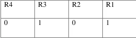
So finally get the redundancy value bits
The value of “1011” in binary 11th so 11th position is an error
Table 8. 15 bit data R1, R2, R3, R4 values is calculated Now the value “1011” Here “1011” the binary bit value is 11th bit, i.e.the 11th position bit is error. “011001111111011”
The 11th bit that bit means change from „0‟ to „1‟ and get the data code is “011011111111011” And calculate second bit
error The value “0101” the binary bit value is 5th bit i.e. 5th position bit is error. “011011111111011” 5th bit error means change the value „1‟ to „0‟ and we get input 15 bit data ”011011111101011” then finally correction two bit errors
get the data code is “011011111101011”
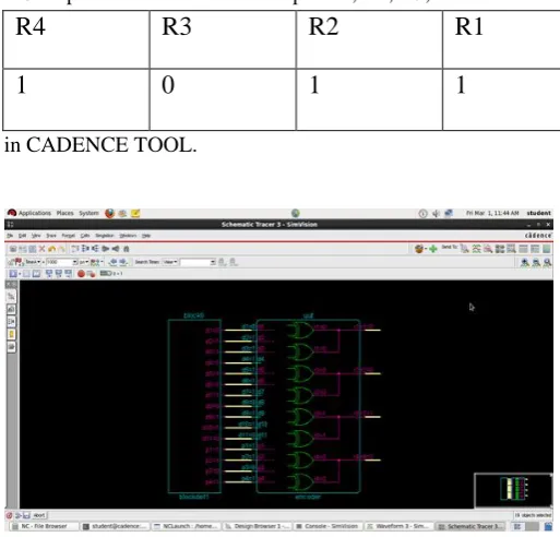
So finally input 15bit data two error bits, i.e. 11th bit position and 5th bit position problem is solved. Remove the redundancy value of four bits get the corrected code word is 11bit data ,i.e. “01101111100” input of original data The error 2nd bit position value 0 to 1 change that value of 0 this error calculates the redundancy bit formula here in the cadence input of 15 bit data With XORING i.e. using the XOR operation then find the output R1, R2, R3, R4 observe
[image:5.595.303.560.486.732.2]in CADENCE TOOL.
Fig 2. Schematic diagram for binary value bits
VI.1ST BIT & 2nd BIT ERROR DESIGN
R4
R3
R2
R1
SIMULATION AND VALIDATION The simulation results of input 15 bit data area
Fig3. Simulation results for 11input data signal & 4parity input signal (15 bit data)
Fig 4. One Error output bit in 11 bit input data schematic diagrams in Cadence
[image:6.595.314.559.51.187.2]The value of input 11 bit data with parity bits and occur in one bit error value here observe the one bit error value Simulation results of 11 bit data
Fig 5. One bit error in parity input signal (11 bit data)
[image:6.595.315.560.234.373.2]Fig 6. Parity bit calculation using 11data bit XOR operation no error value
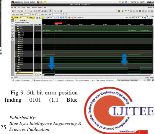
[image:6.595.55.300.320.467.2]Fig 7. Error find in 5th position bit of 15 Bit input signal using 4 redundancy bits
Fig 8. Input 15bit data for error bit signals (5,11)
[image:6.595.315.560.421.563.2] [image:6.595.55.301.564.704.2] [image:6.595.297.560.609.837.2]signals)(0,0 green signals)
Fig 10. 11th bit error position finding 1011 (0 Blue signal)(1,1,1 green signals)
VII.CONCLUSION
The author using Hamming Code is entirely capable of calculating single error detection and correction, also calculate the double bit error detection and correction, then data input and output of the method of the Hamming Code must be a result of the powers of 2 with input power of values must be heavier than one with a length of input data.
VIII.
FUTURE SCOPE
In this 15 bit data, calculate the two error bit, i.e. double bit error finds in given input 15 bit data, 11 bits are message and 4 bits are parity bits. Here using 4 bit parity bits observe two error bits and work proposed to 32 bit ,64 bit,128 bit these are 3bit error and 4 bit errors and 10 bit error detection and correction possible when instead of 1st bit error & 2nd bit error this bit location are cannot be changed as per as error value .
ACKNOWLEDGMENT
The authors would like to acknowledge and thanks to all my faculty Department of ECE, GMRIT (affiliated to JNTU KAKINADA).I sincerely thanks to Dr.V.Kannan Department of ECE, GMRIT.
REFERENCES
1. Dr. Anil Kumar Singh,”Error detection and correction by hamming code‟‟, 978-1-5090-0467-6/16/$31.00 ©2016 IEEE.
2. Pranjali Pothare, Prajakta Ambatkar, Payal Patre, Karishma Padole, Shilpa Lende, Ankita Belekar “Hamming Code For Single Bit Error Detection & Error Correction With Even Parity Using Vhdl” (IJARCET), Volume 4 Issue 1, January2015, pp. 262-265, 2278 – 1323. 3.Vivek Singh, RahulKumar, ManishKumar Upadhyay, “VHDL Code for
Single Bit Error Detection and Correction with Even Parity Check Method Using Xilinx” IJARSE, Vol1, Issue1, 2013.
4.Brajesh Kumar Gupta1, Rajeshwar Lal Dua2 and B. Surya Narayana Raju3“30 BIT HAMMING CODE FOR ERROR DETECTION AND CORRECTION WITH ODD PARITY METHOD BY USING VHDL” IJCSC Vol. 3, No. 1, June 2012.
AUTHORSPROFILE