UNIVERSITI TEKNIKAL MALAYSIA MELAKA
IMPROVEMENT ON WATER PUMP BLADE DESIGN BY
USING CFD SIMULATION
This report is submitted in accordance with the requirement of the Universiti Teknikal Malaysia Melaka (UTeM) for the Bachelor of Manufacturing
Engineering Technology (Product Design) with Honours.
by
TEONG JET FANG
B071410210 940302-01-5292
UNIVERSITI TEKNIKAL MALAYSIA MELAKA
BORANG PENGESAHAN STATUS LAPORAN PROJEK SARJANA MUDA
TAJUK: IMPROVEMENT ON WATER PUMP BLADE DESIGN BY USING CFD SIMULATION
SESI PENGAJIAN: 2017/18 Semester 2
Saya TEONG JET FANG
mengaku membenarkan Laporan PSM ini disimpan di Perpustakaan Universiti Teknikal Malaysia Melaka (UTeM) dengan syarat-syarat kegunaan seperti berikut:
1. Laporan PSM adalah hak milik Universiti Teknikal Malaysia Melaka dan penulis. 2. Perpustakaan Universiti Teknikal Malaysia Melaka dibenarkan membuat salinan untuk
tujuan pengajian sahaja dengan izin penulis.
3. Perpustakaan dibenarkan membuat salinan laporan PSM ini sebagai bahan pertukaran antara institusi pengajian tinggi.
4. **Sila tandakan ( )
SULIT
TERHAD
TIDAK TERHAD
(Mengandungi maklumat yang berdarjah keselamatan atau kepentingan Malaysia sebagaimana yang termaktub dalam AKTA RAHSIA RASMI 1972)
(Mengandungi maklumat TERHAD yang telah ditentukan oleh organisasi/badan di mana penyelidikan dijalankan)
Alamat Tetap:
NO. 39, JALAN TUN RAZAK, 85400, CHAAH,
JOHOR.
Tarikh: ________________________
Disahkan oleh:
Cop Rasmi:
Tarikh: _______________________
DECLARATION
I hereby, declared this report entitled “Improvement on Water Pump Blade Design by Using CFD Simulation” is the results of my own research except as cited in references.
Signature : ………
Author’s Name : ………
APPROVAL
This report is submitted to the Faculty of Engineering Technology of UTeM as a partial fulfilment of the requirements for the degree of Bachelor of Manufacturing Engineering Technology (Product Design) with Honours. The member of the supervisory is as follow:
………
i
ABSTRAK
ii
ABSTRACT
iii
DEDICATION
iv
ACKNOWLEDGEMENT
v
TABLE OF CONTENT
Abstrak i
Abstract ii
Dedication iii
Acknowledgement iv
Table of Content v
List of Tables viii
List of Figures ix
List Abbreviations, Symbols and Nomenclatures xiii
CHAPTER 1: INTRODUCTION
1.1Background 1
1.2 Problem Statement 3
1.3 Objective 4
1.4Scope 4
CHAPTER 2: LITERATURE REVIEW
2.1 Type of Pump 5
2.1.1 Positive Displacement Pump 6
2.1.2 Centrifugal Pump 7
2.2 Pump Output 8
2.2.1 Flow Rate 8
2.2.2 Head 10
2.2.3 Headlosses 11
2.2.4 System Curve and Pump Performance Curve 13
2.3 Power 16
2.4 Rotational Speed and Specific Speed 17
vi
2.5.1 Impeller Size 20
2.5.2 Type of Flow 21
2.5.3 Basic Vector Diagram 22
2.5.4 Type of Blade 23
2.6 Cavitation 24
2.6.1 Method to Prevent Cavitation 28
2.7 Method to improve pump performance 29
2.7.1 Parameterisation 31
2.7.1.1 Outlet Diameter 32
2.7.1.2 Outlet Angle 32
2.7.1.3 Inlet Angle 36
2.7.1.4 Number of Blades 36
2.7.1.5 Blade Thickness 37
CHAPTER 3: METHODOLOGY
3.1 Flow chart 38
3.2 Methodology planning 40
3.2.1 Collect Data and Pump Specification 40 3.2.2 Existing Model Conceptualisation and CFD Simulation 40
3.2.3 Redesign Models and CFD Simulation 42
3.2.4 Analysis and Result Comparison 43
CHAPTER 4: RESULT AND DISCUSSION
4.1 Result 44
4.1.1 Base Impeller Parameter Calculation and Design 45
4.1.2 Impeller Geometry Generation 48
4.1.3 Testing Model Parameter and Geometry Generation 51
4.1.4 CFD Simulation 61
4.1.5 Result of CFD 63
4.1.6 Result Comparison 76
vii
4.1.8 Overall Result Comparison 81
4.2 Discussion 82
CHAPTER 5: CONCLUSION & FUTURE WORK
5.1 Conclusion 84
5.2 Recommendation 85
REFERENCES 86
APPENDICES
viii
LIST OF TABLES
4.1 Pump specification 44
4.2 Range of specific speed in each impeller shape 45 4.3 Head coefficient for different pump type 47
4.4 Calculated impeller parameter 48
4.5 Calculated value for R1, R2, β1, β2 and ρ for base impeller 49
4.6 Parameter for each model 51
4.7 Calculated value for R1, R2, β1, β2 and ρ for impeller 5 53 4.8 Calculated value for R1, R2, β1, β2 and ρ for impeller 6 54 4.9 Calculated value for R1, R2, β1, β2 and ρ for impeller 7 55 4.10 Calculated value for R1, R2, β1, β2 and ρ for impeller 8 56 4.11 Calculated value for R1, R2, β1, β2 and ρ for impeller 9 57 4.12 Calculated value for R1, R2, β1, β2 and ρ for impeller 10 58 4.13 Calculated value for R1, R2, β1, β2 and ρ for impeller 11 59 4.14 Calculated value for R1, R2, β1, β2 and ρ for impeller 12 60 4.15 Comparison of head for different blade number impeller 76 4.16 Comparison of head for different inlet blade angle 77 4.17 Comparison of head for different outlet blade angle 78 4.18 Calculated value for R1, R2, β1, β2 and ρ for optimized impeller 79 4.19 Result comparison between optimized impeller with base impeller 81 and impeller 3, 5, 11 which generate highest head in each parameter
ix
LIST OF FIGURES
1.1 Centrifugal pump and sectional view 2
2.1 Example of positive displacement pump 6
2.2 Classification of positive displacement pumps 6
2.3 Liquid flow through the pump 7
2.4 Different kinds of Centrifugal Pump 7 2.5 Predicted head-flow curve at different rotational speed 9 2.6 Calculation examples of volume flow rate and mass flow rate 9 2.7 Graph of friction loss curve of old pipe and new pipe 12 2.8 Graph of friction head loss versus flow 12 2.9 Graph of total system head versus flow 13
2.10 Graph of head-flow curve 14
2.11 Centrifugal Pump Performance Curves 14
2.12 Centrifugal pumping system head curves vs pump head curve 15 2.13 Effect of impeller trimming on pump performance 16 2.14 Graph of shaft power versus discharge for various rotating speed 17 2.15 Performance curves for varying rotational speed with a constant 17 impeller diameter
2.16 Centrifugal pump impeller 19
2.17 Open impeller; semi-open impeller; closed impeller 19
2.18 Type of flows 21
2.19 Specific speed and standard specific scale for impeller type 22
2.20 Inlet and discharge vector diagrams 23
2.21 Types of impeller blade base on curvature of blades 23 2.22 Pressure and Velocity contour of impeller 24
2.23 Cavitation in a Centrifugal Pump 25
x 2.25 Static pressure distribution for different impellers at different 27 speeds and Gas volume friction evolution with different impellers
at different speeds
2.26 Cavitation analysis at a constant speed with different mass flow rate 28
2.27 Graph of NPSH vs Flow Rate 29
2.28 Graph of pump efficiency versus discharge for various rotating speed 30 2.29 Computational domain for numerical analysis of the impeller 31 2.30 Graph of percentage variation of the head and hydraulic efficiency 33 curves with outlet blade angle for the examined impellers
2.31 Graph of pump efficiency vs output blade angle and theoretical head 34 vs output blade angles
2.32 Efficiency is the highest in impeller 3 as the inlet angle decreases and 35 outlet angle increases
2.33 Result table of Chaudhari et al. (2013) with different parameters 36
3.1 Process planning flow chart 39
3.2 ANSYS Fluent 41
3.3 Circular Arc Drawing Method 42
4.1 Efficiencies of single-stage, single-entry, radial pumps 45 4.2 Graph of tan β2 against specific speed 47
4.3 Radial type impeller shape 48
4.4 Graph of angle against concentric ring radius 49
4.5 Base impeller blade 50
4.6 Base impeller geometry 50
4.7 Geometry and blades of impeller 1,2,3 and 4 52 4.8 Graph of angle against concentric ring radius of impeller 5 53
4.9 Blade of impeller 5 53
4.10 Graph of angle against concentric ring radius of impeller 6 54
4.11 Blade of impeller 6 54
xi
4.13 Blade of impeller 7 55
4.14 Graph of angle against concentric ring radius of impeller 8 56
4.15 Blade of impeller 8 56
4.16 Graph of angle against concentric ring radius of impeller 9 57
4.17 Blade of impeller 9 57
4.18 Graph of angle against concentric ring radius of impeller 10 58
4.19 Blade of impeller 10 58
4.20 Graph of angle against concentric ring radius of impeller 11 59
4.21 Blade of impeller 11 59
4.22 Graph of angle against concentric ring radius of impeller 12 60
4.23 Blade of impeller 12 60
4.24 Fluid domain 61
4.25 Meshing of domain 61
4.26 Static pressure at inlet and outlet of base impeller 63 4.27 Static pressure at inlet and outlet of impeller 1 64 4.28 Static pressure at inlet and outlet of impeller 2 65 4.29 Static pressure at inlet and outlet of impeller 3 66 4.30 Static pressure at inlet and outlet of impeller 4 67 4.31 Static pressure at inlet and outlet of impeller 5 68 4.32 Static pressure at inlet and outlet of impeller 6 69 4.33 Static pressure at inlet and outlet of impeller 7 70 4.34 Static pressure at inlet and outlet of impeller 8 71 4.35 Static pressure at inlet and outlet of impeller 9 72 4.36 Static pressure at inlet and outlet of impeller 10 73 4.37 Static pressure at inlet and outlet of impeller 11 74 4.38 Static pressure at inlet and outlet of impeller 12 75
4.39 Graph of head against number of blades 76
xiii
LIST OF ABBREVIATIONS, SYMBOLS AND
NOMENCLATURE
CAD - Computer-Aided Design CCD - Central Composite Design CFD - Computational Fluid Dynamics SST k-ω - Shear Stress Transport k-omega
H - Head Pressure
Q - Flow Rate
n - Rotational Speed
Ns - Specific Speed
P - Shaft Power
ηv - Volumetric Efficiency
D1 - Inlet Diameter
D2 - Outlet Diameter
β1 - Inlet Blade Angle
β2 - Outlet Blade Angle
1
CHAPTER 1
INTRODUCTION
1.1 Background
Water pump is a device used to increase water pressure in order to transfer water from one point to another for some purpose (Abelin et al. 2006). For example, it can be used to provide energy in hydraulic system, to transfer water for processing and also used to provide cooling and lubrication services for industrial, municipal and residential uses. Due to various conditions and purposes, water pump is classified and being chosen for an application. Typically, the types of water pumps are positive displacement pump and centrifugal pump, which have the same function in transfer water but different theory in operation. However, centrifugal pump is the main subject to be discussed and investigated in this project.
2 Figure1.1: Centrifugal pump and sectional view. (Russell, 2016)
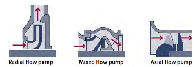
Impeller is a main component in water pump as it accelerates the flow of a fluid and increase the pressure inside to discharge water. The design of the impeller has a critical effect to the performance of a pump. The type of impellers like closed impeller, open impeller and semi-open impeller are considered for different type and properties of the fluid in the pump. The type of flow in the impeller part is considered as the specific speed for each pump is different. Therefore, the impellers for different flows have a different design, for example radial flow impeller, axial flow impeller and mixed flow impeller.
In addition to this, geometry and parameter of the impeller will alter the pressure or head formed. Inappropriate design and parameter of impeller will cause the defect to occur and then affect the pump performance. The critical perspectives of parameters are the impeller diameter, number of blades, outlet blade angle, and inlet blade angle. These parameters are variable, which can be changed to improve the pump performance.
This project is to improve water pump performance by improving the design of the blade (impeller). To identify the performance of the pump and impeller, analysis on both the original impeller and optimised impellers is done, after that the results are compared to find out which has the highest performance. The performance of the impeller and pump can be determined by observing the pressure contour on the impeller and then based on the theory to find out which area is the cavitation zone. Otherwise, from the result of the analysis, the output data like head, discharge rate and efficiency can be
A Stuffing Box B Packing C Shaft D Shaft Sleeve E Vane F Casing
G Eye of impeller H Impeller I Casing wear ring J Impeller
3 obtained, and then comparison is done to determine the optimise performance of impeller and pump.
Computational Fluid Dynamics (CFD) analysis is useful software which can visualise the internal flow of the pump impeller. After modelling the impeller design in CAD, the cavity is then created from the model. This cavity is used as the domain of fluid flow for numerical analysis. After that, it will be imported into software which supports CFD analysis. Then, CFD process is performed to run the analysis by following the process: pre-processing, solver, and then post-processing.
List of design parameter and geometry will be created as the testing models. The same numerical method and same boundary condition will be applied on each of the testing models. The best impeller design parameters will be selected and compromise the parameters to create an optimized impeller. The improvement of optimized impeller is determined based on the rise of head generated.
1.2 Problem Statement
A pump blade design with good performance will operate well in the pump and
raise the pump performance as well. Shyam Karanth (2014) mentioned that optimizing
the cost and increasing the overall efficiency of the pump are methods to optimize the pump performance.
Since the impeller design is a factor to influence the efficiency and performance of a pump, pump performance will be lower as the impeller with inappropriate design and parameter is installed.
4
1.3 Objective
This project is aimed to improve the performance of water pump. As the impeller is the major component in water pump, to speed up the fluid velocity and add kinetic energy to the fluid. Hence, improvement on impeller leads to improve pump performance as well. The followings are the objectives for this project:
1. Initial study of base impeller geometry using CFD. 2. CAD model development of new impeller design. 3. CFD Simulation study of design improvement.
1.4 Scope
This project scope is divided into three parts, they are model out the original water pump blade design based on the pump specification, do analysis by using CFD simulation, conduct the testing model to do analysis and compare with the original model.
Mathematical method is used to calculate the parameters of original pump based on the pump specification. From the parameters obtained, the original model is modelled using SolidWorks. The design and parameters of original water pump blade will be used as the benchmark.
5
CHAPTER 2
LITERATURE REVIEW
2.0 Introduction
Water pump is a device widely used to provide the motive force in hydraulic systems, to transfer fluids for processing, and to provide cooling and lubrication services. Most manufacturing plants, commercial buildings, and municipalities rely on pumping systems in various purposes for their daily operation. For example, pumps are used to provide water for heat transfer in heating, ventilation, and air-conditioning (HVAC) systems, water and wastewater transfer and treatment and for land drainage (Abelin et al. 2006). Therefore, the operating condition and design parameters that yield optimal output and maximum efficiency with lowest power consumption is important to be find out (Ramasamy & Ganesan 2016).
2.1 Type of Pump
6 2.1.1 Positive Displacement Pump
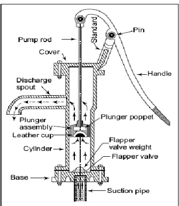
[image:23.612.254.437.257.468.2]Positive displacement pumps decrease displacement volume (collapsing volume action) with a piston stroke or shaft rotation to pressurize and discharge fluid. Basically, this pump squeezes an amount of fluid equal to the displacement volume of the system. As the displacement volume is fixed, the generated flow rates are directly proportional to the speed. Typically, positive displacement pumps are used in low-flow, high-head applications and with high-viscosity fluids.
Figure 2.1: Example of positive displacement pump: Sectional view of head assembly of a shallow-well lifts pump. (Khepar et al. 2008)
[image:23.612.171.525.539.680.2]7 2.1.2 Centrifugal Pump
Centrifugal pump is a type of a turbo machine which converts mechanical energy to dynamic pressure to enable the lifting of liquid from lower level to higher level due to centrifugal action (Muttalli et al. 2014).
Centrifugal force of a spinning impeller adds kinetic energy to a fluid. The high-velocity fluid leaves the impeller tip to a diffuser, which is a chamber that connects to the discharge piping. The moving fluid will slow down at the pump diffuser section and a higher pressure is converted from the kinetic energy of the fluid.
Centrifugal pumps are used typically in high-flow, low-head applications in which fluid viscosity is not excessively high. It suffers less wear and require less part replacements. It requires only a minor amount of downtime for packing or mechanical seals as well although it must be replaced periodically.
Figure 2.3: Liquid flow through the pump. (Grundos 2004)
[image:24.612.192.491.385.526.2] [image:24.612.185.495.573.681.2]