University of Southern Queensland
Faculty of Health, Engineering and Sciences
Implementation of Negative Phase Sequence
Protection in the High Voltage Distribution Network
A dissertation submitted by
Scott Taylor
In fulfilment of the requirements of
ENG4111 and ENG4112 Research Project
Towards the degree of
Bachelor of Engineering (Honours)
Power Major
Abstract
Negative phase sequence protection is effective at detecting certain faults, and is now available on modern reclosers. However, it has not been widely utilised in electrical distribution networks. This thesis reviews and researches protection schemes with a focus on negative phase sequence protection and puts forward methods for its implementation specific to the distribution network.
Charles Fortescue’s 1918 paper detailed his discovery of symmetrical components on which much of modern power system analysis and protection is based (Fortescue CL 1918). The theory of symmetrical components is essentially a way of describing and modelling the relationship between the three phases of an electrical distribution network.
Faults on the distribution network result in current flow with specific characteristics. Modern electronic reclosers can be programmed to analyse and operate for faults based on these sequence (symmetrical) components.
Negative phase sequence protection can have a pickup setting lower than normal load current, and still detect particular fault types including line to line faults. This gives negative phase sequence protection a distinct advantage over traditional overcurrent techniques and means that protection coverage can be extended further into the network without the need for line reconducting or the installation of fuses.
Whilst there are a number of existing papers that deal with traditional protection techniques, there are not many that focus on negative phase sequence protection, especially for the distribution network. This thesis aims to facilitate discussion on negative phase sequence protection, increase network employee’s familiarity of it, explore where it is and is not effective, and put forward methodologies with practical examples in the form of case studies for its implementation.
Limitations of Use
The Council of the University of Southern Queensland, its Faculty of Health, Engineering and Sciences, and the staff of the University of Southern Queensland, do not accept any responsibility for the truth, accuracy or completeness of material contained within or associated with this dissertation.
Persons using all or any part of this material do so at their own risk, and not at the risk of the Council of the University of Southern Queensland, its Faculty of Health, Engineering and Sciences or the staff of the University of Southern Queensland.
This dissertation reports an educational exercise and has no purpose or validity beyond this exercise. The sole purpose of the course pair entitles “Research Project” is to contribute to the overall education within the student’s chosen degree program. This document, the associated hardware, software, drawings, and any other material set out in the associated appendices should not be used for any other purpose: if they are so used, it is entirely at the risk of the user.
Certification of Dissertation
I certify that the ideas, designs and experimental work, results, analyses and conclusions set out in this dissertation are entirely my own effort, except where otherwise indicated and acknowledged.
I further certify that the work is original and has not been previously submitted for assessment in any other course or institution, except where specifically stated.
Scott Taylor
Student Number: 0061021892
Acknowledgments
Essential Energy sponsored not only this thesis, but my journey through the degree program, for which I am very grateful.
Associate Professor Tony Ahfock gave sound, practical advice and guidance as my university supervisor for this thesis. He kindly gave time late at night and on weekends to contribute to my education and completing this degree. Anyone that has had the privilege of being in one of Tony’s lecturers understands that he is engaging, relatable, and passionate about engineering and his students.
Doug Wray and Bill Howell are two highly respected senior engineers at Essential Energy that kindly agreed to be industry supervisors for this thesis. Thank you for your input and guidance.
Quite a few people contributed to this thesis by reviewing and providing comments that were invaluable. Particular thanks goes to Lis and Sheila Wallace.
My academic journey has not just been confined to the six years of this degree. There have been many people that have contributed over the 21 years that I have been in the electrical industry. The crew from what was Western Power when I started my apprenticeship including Adam, Eddie, Tony, Sean, Paula, and Jake ‐ who took me under his wing and believed in me. Thank you. It meant a lot.
Graeme Bell, another respected senior engineer, was the person who offered me the opportunity of entering the professional realm and furthering my career. Thank you.
My time as a zone substation designer presented opportunities, challenges, and responsibilities that would make it one of the defining periods of my career. It was whilst with this team that my university studies commenced. It was a great team, and great time, albeit with some of the regular ups and downs along the way. Thank you to all of the team, particularly Jason and Andrew who progressed through with me. And, thank you to Trent from whom I learnt much, and that I carry with me and apply often.
My current team, being Alexei, Andrew, Bill, Doug, Jo, Piet, Peter, and Tom. I enjoy working with you, and thank you for your support. Vince Kelly, our manager, has also been a great supporter of engineering. I appreciate the opportunity of being part of the team.
Alexei Watson, thank you for being a study partner and friend. You will be writing one of these before you know it, and I’m sure it will be a great thesis.
Andrew Close, my work colleague, study partner, and most of all, my friend. There was probably a 1,000 times that I felt like this might be a mountain too high to pass, but you were there each time. You get your own paragraph in my thesis because I’m not sure there would have been one if it were not for you. Thank you.
Tennille, thank you for opening your home and having me there to study with Andrew for so many nights over the years.
To my friends and family. Basically, I am sorry. I’ve missed out on a lot with you over the years whilst I have been studying. But, I’m sure you understand that the study in some ways has also been a good place to be at times. Please know that you have been in my thoughts. To my mates from ‘the old days’, Beno, Deano, Mark, Camo, Trent, Tom, you define so much of who I am, and you will hear from me soon. Pat and Brenton, we need to get these Valiants and bikes out on the road together and start having some outings.
Charlie and Lis Wallace, I always enjoy spending time with you, and hope to be doing so more in the future.
Kay and Barry Taylor, my mum and dad. Thank you for always being there. Your love and support is a constant inspiration, and I aspire to be as good a person as both of you are. Shane and Kim, my siblings, and their partners Amanda and Greg. I look forward to spending more time with you soon.
Contents
Abstract ... ii
Limitations of Use ... iii
Certification of Dissertation ...iv
Acknowledgments ... v
Contents ... vii
List of Figures ... xii
List of Tables ... xvii
Chapter 1 ... 1
1 Introduction ... 1
1.1 Background ... 1
1.2 Project focus ... 2
1.3 Project findings and developments ... 3
1.4 Project specification and objectives ... 4
1.5 Overview of thesis ... 5
Chapter 2 ... 6
2 Literature Review ... 6
2.1 Overview ... 6
2.2 Early evolution of electrical theory ... 6
2.3 Power system analysis ... 7
2.3.1 Phase rotation ... 7
2.3.2 Sequence components ‐ Definition ... 8
2.3.3 The operator ... 11
2.3.4 Sequence components ‐ Solving ... 12
2.3.5 Sequence components ‐ Current ... 12
2.3.6 Sequence components ‐ Impedances ... 13
2.3.7 Fault calculations ... 14
2.3.8 Source impedance ... 15
2.3.9 Types of faults ... 15
2.3.10 Three line faults ... 16
2.3.11 Single line to earth faults ... 16
2.3.13 Double line to earth faults ... 20
2.3.14 Open circuit conductor faults... 20
2.4 Power system protection ... 21
2.5 Traditional protection schemes ... 21
2.5.1 Overcurrent protection ... 22
2.5.2 Earth fault protection ... 23
2.5.3 Sensitive earth fault protection ... 23
2.5.4 Primary and backup protection ... 25
2.6 Negative phase sequence protection ... 26
2.6.1 Discussion ... 26
2.6.2 Techniques ... 26
2.6.3 Devices ... 28
2.6.4 Applications and advantages ... 29
2.6.5 Limitations ... 30
2.6.6 Disadvantages ... 31
2.6.7 Mitigation measures ... 31
2.7 Existing protection schemes ‐ Essential Energy policies ... 32
2.7.1 Policy relevance... 32
2.7.2 CEOP8002 ‐ Protection Guidelines ... 32
2.7.3 CEOP8012 ‐ Protection Guidelines ‐ Generator ... 33
2.7.4 CEOS5099 ‐ Distribution Transformer Fusing ... 33
Chapter 3 ... 34
3 Discussion ... 34
3.1 Consequential effects ... 34
3.2 Ethical responsibility ... 34
3.3 Safety issues ... 35
Chapter 4 ... 37
4 Methodology ... 37
4.1 Methodology overview ... 37
4.2 Existing protection scheme production methodology ‐ Essential Energy ... 37
4.2.1 Data acquisition... 37
4.2.2 Feeder modelling ... 38
4.3 Inline series fuses ... 44
4.4 Implementation of negative phase sequence protection ... 45
4.4.1 Negative phase sequence current settings and configuration ... 47
4.4.2 Equivalent phase current calculations ... 48
4.4.3 Perceived malgrades on the same recloser ... 48
4.4.4 SWER lines and negative phase sequence protection ... 50
4.4.5 Single phase loads and negative phase sequence protection ... 50
4.4.6 Practical applications for negative phase sequence protection ... 51
4.4.7 Negative phase sequence protection on the last feeder recloser ... 52
4.4.8 Negative phase sequence protection on the second last feeder recloser 53 4.5 Methodology examples ... 55
4.5.1 Method 1 ... 55
4.5.2 Method 2 ... 56
4.5.3 Method 3 ... 57
4.5.4 Method 4 ... 58
4.5.5 Method 5 ... 59
4.5.6 Method 6 ... 60
4.5.7 Method 7 ... 61
Chapter 5 ... 62
5 Case Study 1 ... 62
5.1 Introduction ... 62
5.2 Munga zone substation ‐ MGA3B2 Willawarrin 11 kV feeder ... 63
5.3 Case study scope ‐ Moparrabah spur ... 64
5.4 Feeder arrangement ... 65
5.5 Feeder loads ... 66
5.6 Recloser 2‐R47010 ... 67
5.7 Fuse F44080 ... 69
5.8 Recloser 2‐R47011 ... 71
5.9 Recloser 2‐R10838 ... 73
5.10 Feeder circuit breaker MGA3B2 ... 76
5.11 Earth fault and sensitive earth fault settings ... 78
5.12 Transformer fuse grading ... 78
5.13 Grading study and summary ... 78
6 Case Study 2 ... 81
6.1 Byabarra zone substation ‐ BYA7781 Yarras 11 kV feeder ... 81
6.2 Case study scope ‐ Entire feeder ... 82
6.3 Feeder arrangement ... 82
6.4 Application of negative phase sequence protection ... 84
6.5 Feeder loads ... 84
6.6 Earth fault and sensitive earth fault settings ... 84
6.7 Recloser 2‐R42233 ... 85
6.8 Recloser 2‐R43302 ... 89
6.9 Recloser 2‐R42951 ... 92
6.10 Recloser 2‐R12105 ... 95
6.11 Recloser 2‐R42221 ... 98
6.12 Feeder circuit breaker BYA7781 ... 101
Chapter 7 ... 103
7 Results, findings and recommendations ... 103
7.1 Discussion ... 103
7.2 Essential Energy protection policies and practices ... 103
7.3 Other recommendations ... 105
7.4 Other findings... 106
7.5 Sincal software anomalies ... 107
7.5.1 Anomaly 1 ... 107
7.5.2 Anomaly 2 ... 108
7.5.3 Sincal anomaly summary ... 108
7.6 Further work ... 109
7.6.1 Impact of low voltage faults ... 109
7.6.2 Power factor and sequence currents ... 109
Chapter 8 ... 110
8 Final Chapter ... 110
8.1 Achievement of project specifications and objectives ... 110
8.2 Conclusion ... 111
References... 112
10 Appendix A ‐ Project specification ... 115
11 Appendix B ‐ Case Study 1 Data ... 116
11.1 Feeder loads ... 116
11.2 Sincal models ... 118
12 Appendix C ‐ Case Study 2 Data ... 123
12.1 Feeder loads ... 123
12.2 Sincal models ... 126
List of Figures
Figure 1‐1: Electricity network overview ... 1
Figure 2‐1: Phase rotation ... 7
Figure 2‐2: Sequence components ‐ Voltage ‐ Traditional representation ... 9
Figure 2‐3: Sequence components ‐ Voltage ‐ Alternate representation ... 9
Figure 2‐4: Unbalanced system sequence and phase components ‐ Relationship ... 11
Figure 2‐5: Unbalanced system sequence and phase components ‐ Deconstructed ... 11
Figure 2‐6: Operator and 2 ... 11
Figure 2‐7: Sequence circuits ‐ ‘a’ phase ... 15
Figure 2‐8: Sequence network ‐ Three line bolted fault ‐ 'a' phase ... 16
Figure 2‐9: Sequence network ‐ Line to earth fault ‐ 'a' phase ... 17
Figure 2‐10: Sequence network ‐ Line to line fault ‐ b phase ... 17
Figure 2‐11: Sequence components ‐ Line to line fault ‐ b to c phase ... 19
Figure 2‐12: Full phase current ‐ Line to line fault ‐ b to c phase ... 19
Figure 2‐13: Sequence network ‐ Double line to earth fault ‐ b phase ... 20
Figure 2‐14: Primary and backup protection ... 22
Figure 2‐15: Overcurrent protection ‐ Time and current grading ... 22
Figure 2‐16: Connection of earth fault relay ... 23
Figure 2‐17: Earth fault and sensitive earth fault ‐ Time and current grading ... 24
Figure 2‐18: Negative phase sequence grading – Method by Basler and others ... 27
Figure 4‐1: Example grading study chart ... 42
Figure 4‐3: Method 1 ... 55
Figure 4‐4: Method 2 ... 56
Figure 4‐5: Method 3 ... 57
Figure 4‐6: Method 4 ... 58
Figure 4‐7: Method 5 ... 59
Figure 4‐8: Method 6 ... 60
Figure 4‐9: Method 7 ... 61
Figure 5‐1: Munga zone substation ... 62
Figure 5‐2: Location diagram ‐ Munga zone substation ... 63
Figure 5‐3: Geographic network diagram ‐ 11 kV feeder MGA3B1 and MGA3B2 ... 65
Figure 5‐4: Single line diagram ‐ 11 kV feeder MGA3B2 ... 66
Figure 5‐5: Single line diagram ‐ Recloser 2‐R47010 ... 67
Figure 5‐6: Single line diagram ‐ Fuse F44080 ... 69
Figure 5‐7: Recloser 2‐R47010, transformer 2‐51403 and fuse F44080 ... 70
Figure 5‐8: Single line diagram ‐ Recloser 2‐R47011 ... 71
Figure 5‐9: Single line diagram ‐ Recloser 2‐R10838 ... 73
Figure 5‐10: Single line diagram ‐ Circuit breaker MGA3B2 ... 76
Figure 5‐11: Single line diagram and protection setting data ‐ Moparrabah spur ... 79
Figure 5‐12: Grading study ‐ MGA3B2 ‐ Moparrabah spur ... 80
Figure 6‐1: Location diagram ‐ Byabarra zone substation ... 81
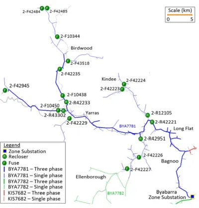
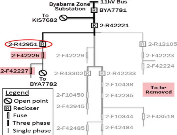
Figure 6‐2: Geographic network diagram – 11 kV feeder BYA7781 ... 83
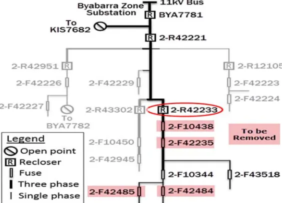
Figure 6‐4: Single line diagram ‐ Recloser 2‐R42233 ... 85
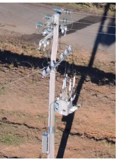
Figure 6‐5: Recloser 2‐R42233 ... 87
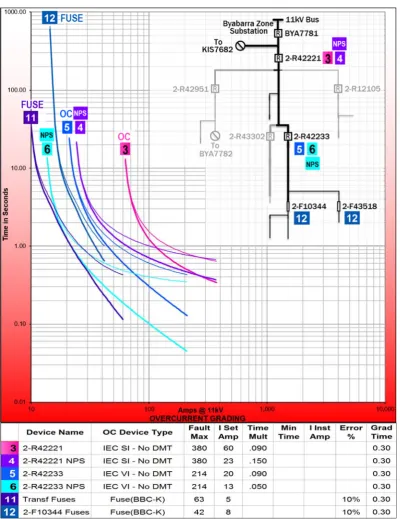
Figure 6‐6: Grading study ‐ Recloser 2‐R42233 ... 88
Figure 6‐7: Single line diagram ‐ Recloser 2‐R43302 ... 89
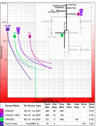
Figure 6‐8: Grading study ‐ Recloser 2‐R43302 ... 91
Figure 6‐9: Single line diagram ‐ Recloser 2‐R42951 ... 92
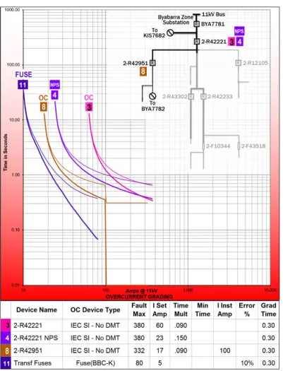
Figure 6‐10: Grading study ‐ Recloser 2‐R42951 ... 94
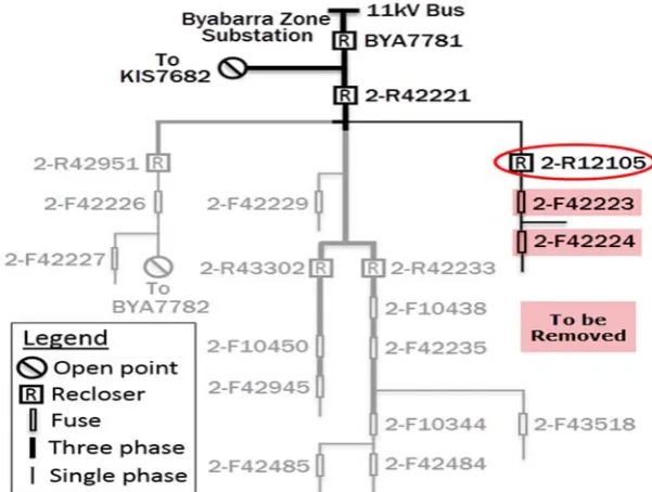
Figure 6‐11: Single line diagram ‐ Recloser 2‐R12105... 95
Figure 6‐12: Recloser 2‐R12105 ... 96
Figure 6‐13: Grading study ‐ Recloser 2‐R12105 ... 97
Figure 6‐14: Single line diagram ‐ Recloser 2‐R42221... 98
Figure 6‐15: Grading study ‐ Recloser 2‐R42221 ... 100
Figure 6‐16: Single line diagram ‐ Circuit breaker BYA7781 ... 101
Figure 11‐1: Load current ‐ Recloser 2‐R47011 ... 116
Figure 11‐2: Load current ‐ Recloser 2‐R10838 ... 116
Figure 11‐3: Load current ‐ Feeder circuit breaker MGA3B1 ... 116
Figure 11‐4: Load current ‐ Feeder circuit breaker MGA3B2 ... 117
Figure 11‐5: Sincal model ‐ Transformer 2‐978054 ... 118
Figure 11‐6: Sincal model ‐ Recloser 2‐R47010 and transformer 2‐51403 ... 118
Figure 11‐7: Sincal model ‐ Transformer 2‐51627 ... 119
Figure 11‐8: Sincal model ‐ Recloser 2‐R47011 ... 119
Figure 11‐10: Sincal model ‐ Recloser 2‐R10838 ... 120
Figure 11‐11: Sincal model ‐ Transformer 2‐50590 ... 121
Figure 11‐12: Sincal model ‐ Feeder circuit breaker MGA3B2 ... 122
Figure 11‐13: Recloser 2‐R47011 ... 122
Figure 12‐1: Load current ‐ Recloser 2‐R42233 ... 123
Figure 12‐2: Load current ‐ Recloser 2‐R43302 ... 123
Figure 12‐3: Load current ‐ Recloser 2‐R42951 ... 124
Figure 12‐4: Load current ‐ Recloser 2‐R12105 ... 124
Figure 12‐5: Load current ‐ Recloser 2‐R42221 ... 124
Figure 12‐6: Load current ‐ Feeder circuit breaker BYA7781 ... 125
Figure 12‐7: Load current ‐ Feeder circuit breaker BYA7782 ... 125
Figure 12‐8: Sincal model ‐ Transformer 2‐40377 ... 126
Figure 12‐9: Sincal model ‐ Fuse 2‐F10344 ... 126
Figure 12‐10: Sincal model ‐ Recloser 2‐R42233 ... 127
Figure 12‐11: Sincal model ‐ Transformer 2‐41181 ... 127
Figure 12‐12: Sincal model ‐ Recloser 2‐R43302 ... 128
Figure 12‐13: Sincal model ‐ Transformer 2‐40561 ... 128
Figure 12‐14: Sincal model ‐ Recloser 2‐R42951 ... 129
Figure 12‐15: Sincal model ‐ Transformer 2‐41767 ... 129
Figure 12‐16: Sincal model ‐ Recloser 2‐R12105 ... 130
Figure 12‐17: Sincal model ‐ Transformer 2‐40882 ... 130
Figure 12‐19: Sincal model ‐ Transformer 2‐10485 ... 131
Figure 12‐20: Sincal model ‐ Feeder circuit breaker BYA7781 ... 132
Figure 12‐21: Recloser 2‐R42221 ... 132
List of Tables
Table 5‐1: Reference table ‐ Protection zone of recloser 2‐R47010 ... 67
Table 5‐2: Protection setting factors ‐ Recloser 2‐R47010 and Fuse F44080 ... 67
Table 5‐3: Additional network data ‐ Protection zone of recloser 2‐R47010 ... 67
Table 5‐4: Reference table ‐ Protection zone of fuse F44080 ... 69
Table 5‐5: Additional network data ‐ Protection zone of fuse F44080 ... 69
Table 5‐6: Reference table ‐ Protection zone of recloser 2‐R47011 ... 71
Table 5‐7: Protection setting factors ‐ Recloser 2‐R47011 and recloser 2‐R10838 ... 71
Table 5‐8: Additional network data ‐ Protection zone of recloser 2‐R47011 ... 71
Table 5‐9: Reference table ‐ Protection zone of recloser 2‐R10838 ... 73
Table 5‐10: Protection setting factors ‐ Recloser 2‐R10838 and circuit breaker MGA3B2 ... 73
Table 5‐11: Additional network data ‐ Protection zone of recloser 2‐R10838 ... 73
Table 5‐12: Reference table ‐ Protection zone of circuit breaker MGA3B2 ... 76
Table 5‐13: Protection setting factors ‐ Circuit breaker MGA3B2 ... 76
Table 5‐14: Additional network data ‐ Protection zone of circuit breaker MGA3B2 ... 76
Table 6‐1: Reference table ‐ Protection zone of recloser 2‐R42233 ... 85
Table 6‐2: Protection setting factors ‐ Recloser 2‐R42233 and recloser 2‐R42221 ... 85
Table 6‐3: Additional network data ‐ Protection zone of recloser 2‐R42233 ... 85
Table 6‐4: Reference table ‐ Protection zone of recloser 2‐R43302 ... 89
Table 6‐5: Protection setting factors ‐ Recloser 2‐R43302 and recloser 2‐R42221 ... 89
Table 6‐7: Reference table ‐ Protection zone of recloser 2‐R42951 ... 92
Table 6‐8: Protection setting factors ‐ Recloser 2‐R42951 and recloser 2‐R42221 ... 92
Table 6‐9: Additional network data ‐ Protection zone of recloser 2‐R42951 ... 92
Table 6‐10: Reference table ‐ Protection zone of recloser 2‐R12105 ... 95
Table 6‐11: Protection setting factors ‐ Recloser 2‐R12105 and recloser 2‐R42221 ... 95
Table 6‐12: Additional network data ‐ Protection zone of recloser 2‐R12105 ... 95
Table 6‐13: Reference table ‐ Protection zone of recloser 2‐R42221 ... 98
Table 6‐14: Protection setting factors ‐ Recloser 2‐R42221 and circuit breaker BYA7781 ... 98
Table 6‐15: Additional network data ‐ Protection zone of recloser 2‐R42221 ... 98
Table 6‐16: Reference table ‐ Protection zone of circuit breaker BYA7781 ... 101
Table 6‐17: Protection setting factors ‐ Circuit breaker BYA7781 ... 101
Chapter 1
1
Introduction
1.1 Background
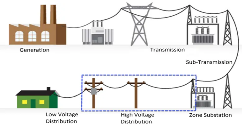
The electricity supply network is generally comprised of generation, transmission, sub‐transmission and distribution as shown in Figure 1‐1. The high voltage distribution network that this thesis will focus on is outlined with a dashed blue line.
The dashed blue line has intentionally not encapsulated the entire low voltage distribution network. Although the low voltage network is an important part of the distribution network, the focus of this thesis will be on the high voltage distribution network.
[image:19.595.101.491.363.567.2]
Figure 1‐1: Electricity network overview. Image adapted from source (EPS Technology 2010)
Generally, the distribution network commences as a ‘feeder’ at a zone substation. These feeders may be overhead or underground construction, typically at a voltage of 11 kV or 22 kV. These feeders supply distribution transformers which lower the voltage to a level that is useable by consumers, being 400 V / 230 V (three / single phase). In some cases, industrial customers may take supply at high voltage direct from the distribution network.
A fuse operates when an electrical current passing through it for a period of time exceeds that for which it is rated. Devices such as circuit breakers, reclosers, and sectionalisers can be programmed with settings to operate for a variety of events, including overcurrent and earth faults. The arrangement of fuses, and the settings of devices on a network, is called the ‘protection scheme’.
A protection scheme is usually produced via the following method:
Creation of a network model using computer software. The model includes conductor type, length, impedance, regulators, and loads.
Complete load flow and fault level analysis on the network.
Research interdependencies such as upstream settings and parameters.
Complete a grading study of the protection scheme. Settings are produced to meet the protection requirements of the network. The settings for each device are then mapped against each other as curves on a grading chart to ensure the scheme operates as intended.
Produce a Protection Setting Advice (PSA) for each device. This contains the detection and operational characteristics that need to be programmed into each protection device.
Field technicians implement the scheme using the PSA’s. This includes programming relays, changing fuse elements, and installing equipment.
1.2 Projectfocus
The focus of this thesis is on a type of protection scheme called negative phase sequence protection. This type of protection is based on Charles Fortescue’s 1918 theory of symmetrical components, which is a method of modelling the behaviour of electrical networks and simplifying the related mathematics. Until relatively recently, the technology required to implement negative phase sequence protection on the distribution network was not available or fiscally viable. However, today, many recloser controllers and numerical relays (for substation circuit breakers) have the ability to deconstruct current phasors into its symmetrical components, and thus utilise them for protection purposes.
The case studies included in this thesis are based on Essential Energy’s network, policies, procedures and data in order to demonstrate the use of negative phase sequence protection in a real world application. However, the concepts and methodologies described in this thesis are equally valid for networks other than Essential Energy’s.
Negative phase sequence protection has been available on some distribution protection devices for approximately 2‐10 years, however, it has not been implemented throughout the electricity supply industry as much as it could be. This may be because:
It is relatively new (in terms of availability).
Electrical supply authorities can be averse to using ‘new’ technology.
There are not many papers written on negative phase sequence protection specifically for the distribution network.
There are not many papers written on how to produce or grade negative phase sequence protection in practical terms. Those that are available assume reclosers in the distribution network do not have negative phase sequence protection.
Due to negative phase sequence protection being relatively new (in terms of availability), it may not be taught in all protection courses, past or present.
Engineers may be reluctant to implement negative phase sequence protection due to not being familiar with it.
1.3 Projectfindingsanddevelopments
This thesis will cover points that were not found, or discussed in detail within any of the documents sourced during the literature review. These points include:
Grading of negative phase sequence protection on the distribution network.
Discussion on the characteristics of negative phase sequence current present on the distribution network during un‐faulted conditions.
Validity, and ability to grade an upstream negative phase sequence pickup below a downstream overcurrent pickup in certain circumstances.
Limitations of negative phase sequence protection related to single phase spurs (two lines of a three line network), and Single Wire Earth Return (SWER).
1.4 Projectspecificationandobjectives
The overall aim of this project is to develop an approach to producing high voltage distribution network protection schemes utilising negative phase sequence protection. However, as detailed in the previous section, given that this type of protection may not be as familiar as traditional techniques for some, this thesis also aims to facilitate and promote discussion about its merits and application. The objectives of this thesis are achieved by performing the following:
1. Review power system analysis theory.
2. Review traditional protection schemes utilised in high voltage distribution networks, being, overcurrent, earth fault, and sensitive earth fault protection.
3. Research negative phase sequence protection theory, techniques, devices, applications, limitations, advantages and disadvantages.
4. Investigate mitigation measures and techniques to overcome or avoid the limitations and disadvantages of negative phase sequence protection.
5. Review existing policies and protection scheme production methodologies utilised at Essential Energy.
6. Produce recommendations to amend Essential Energy’s protection policies and practices to include negative phase sequence protection where appropriate.
7. Produce case studies of protection schemes utilising negative phase sequence protection. These will include a variety of network arrangements and faults that may occur on the high voltage distribution networks that typically supply regional areas. The case studies will cover network modelling, grading studies, and settings.
1.5 Overviewofthesis
This thesis is organised as follows:
Chapter 1 provides the background, focus and objectives of the project.
Chapter 2 reviews existing literature and concepts relevant to the project. This includes
symmetrical components, power system analysis, faults, traditional protection schemes, negative phase sequence protection, and network policy relevant to the case studies included as chapter 5 and 6.
Chapter 3 discusses the consequential effects, ethics and safety matters related to the
implementation of negative phase sequence protection.
Chapter 4 reviews the existing methodologies used for producing protection schemes,
and puts forward amended methodologies for the implementation of negative phase sequence protection.
Chapter 5 contains a case study that applies the methodologies described in chapter 4 to
a real world distribution network and demonstrates its advantages and limitations. The case study is based on the 11 kV feeder from Munga zone substation called MGA3B2 Willawarrin.
Chapter 6 contains a second case study based on the 11 kV feeder from Byabarra zone
substation called BYA7781 Yarras.
Chapter 7 contains results, findings and recommendations put forward by this thesis.
Chapter 8 details to what extent the project specifications and objectives were met, and
provides a conclusion to the thesis.
Chapter 2
2
Literature Review
2.1 Overview
Although modern computer modelling software is normally used to analyse power systems today, the engineer should still understand the concepts and methodologies to manually perform calculations so that results can be checked and confirmed. For this reason, a basic summary of power system analysis will be provided in this thesis.
2.2 Earlyevolutionofelectricaltheory
There have been many people throughout history that have made observations, and proposed theories as to the nature and behavior of electricity. A summary of the notable, and indeed interesting works that are of relevance to this thesis are discussed in this chapter.
One of the earlier attempts to describe electricity was by Gilbert (Gilbert W 1600) in his work titled De Magnete. Gilbert covers a number of topics that includes discussion on the earth as a globe, gravity, magnetism, and electricity as being a type of invisible fluid, or effluvium, which is released from some objects when rubbed.
The belief that electricity was a type of fluid continued for some time and its nature was debated by various people. Charles Du Fay proposed that there were actually two different types of this fluid (Du Fay CFdC 1733, p. 263), which was opposed by Benjamin Franklin (Home RW 1972) who instead argued that there was only one type of fluid which flowed from one point to another.
In 1913, Charles Fortescue was mathematically investigating the behavior of induction motors operating in unbalanced conditions when he discovered a symmetry in the results he attained (Fortescue CL 1918). He found that the solution always reduced to the sum of two or more symmetrical components. Fortescue realised that there was application for this discovery beyond describing motor behavior. This led him to write the paper titled
Method of Symmetrical Co‐Ordinates Applied to the Solution of Polyphase Networks, which was released in 1918. The operation of modern protection relays and reclosers is largely based on Fortescue’s symmetrical components.
2.3 Powersystemanalysis
The following sections provide a summary of power system analysis and electrical theory relevant to this thesis.
2.3.1 Phaserotation
The electrical distribution network consists of three phasors commonly referred to as a,
b and c phase. In a balanced system, these phasors are equal in magnitude and separated by 120°. As the phasors are sinusoidal, and are displaced by 120°, the ‘phase rotation’ can be determined by the order in which they reach their peak values. Where the order is a,
b then c, the phase rotation is said to be positive or forward. It is convention that phase rotation is drawn with an anticlockwise rotation from the perspective on an observer. Where the order is a, c then b, the phase rotation is said to be reverse.
It should be noted that both positive and reverse phase rotation is drawn with an anticlockwise rotation, and that it is the order of the phases that is ‘reversed’.
2.3.2 Sequencecomponents ‐ Definition
As discovered by Fortescue, a voltage phasor (e.g. a phase) can be represented and constructed by analysing its sequence components. These sequence components are sometimes also called symmetrical components and are used to reduce the complexity of solving electrical quantities in power systems (Marx S & Bender D 2013). There are three sequence components that may be present in each voltage phasor, and indeed current phasor, however for now we will concentrate on voltage.
The sequence components are called positive, negative and zero sequence, and should be considered to be mathematical components of a model that represents actual quantities such as voltage and current. To that end, it should be noted that the presence of negative sequence quantities does not mean that voltage or current is flowing in the opposite direction to its voltage or current phase. It should also be noted that all three sequence components are drawn with an anticlockwise direction. It is the order of the phases that is changed, as is the case for positive and reverse phase rotation. Refer to Figure 2‐2.
A voltage phasor (e.g. a phase) is equal to the addition of its positive, negative and zero sequence components, as shown in equations (2‐1) to (2‐3).
(2‐1)
(2‐2)
(2‐3)
Where:
V = Voltage phasor for a phase V = Voltage phasor for b phase V = Voltage phasor for c phase
V = Positive sequence voltage of a phase
V = Negative sequence voltage of a phase
V = Zero sequence voltage of a phase
V = Positive sequence voltage of b phase
V = Negative sequence voltage of b phase
V = Zero sequence voltage of b phase
V = Positive sequence voltage of c phase
V = Negative sequence voltage of c phase
V = Zero sequence voltage of c phase
Grainger and Stevenson, in ‘Power System Analysis’ (Grainger JJ & Stevenson WD 1994) describes Fortescue’s sequence components as applied to a three phase system as:
Positive sequence components consist of three phasors equal in magnitude, displaced from each other by 120° in phase, and having the same phase sequence as the original phasors. i.e. abc.
Negative sequence components consist of three phasors equal in magnitude, displaced from each other by 120° in phase, and having the phase sequence opposite to that of the original phasors. i.e. acb.
Zero sequence components consist of three phasors equal in magnitude and with zero phase displacement from each other.
Figure 2‐2: Sequence components ‐ Voltage ‐ Traditional representation
Figure 2‐3: Sequence components ‐ Voltage ‐ Alternate representation
Figure 2‐2 shows sequence components as usually depicted in text books and papers, including those by Grainger and Stevenson (Grainger JJ & Stevenson WD 1994), Wang and Hamilton of Basler Electric Company (Wang J & Hamilton R 2010) and Zocholl of Schweitzer Engineering Labs (Zocholl SE Unknown). However, this representation of sequence components may be misleading, or confusing in some circumstances. Although sequence components do not necessarily need to be described as a set rotating phasors, they commonly are. When they are described as rotating phasors, each set must rotate around a common point, or origin as labeled in Figure 2‐3. When this is taken in conjunction with Grainger and Stevens definition of zero sequence current, being ‘three phasors equal in magnitude and with zero phase displacement from each other’, then it stands that they must be effectively stacked on top of each other and rotating around an origin, as shown in Figure 2‐3. Additionally, if observed on laboratory test instruments, it is also likely that zero sequence components would appear this way, more so than as commonly shown in text books and Figure 2‐2. It should be noted that no other source or paper was discovered during this project that represented zero sequence elements in this manner.
In a balanced three phase system, there are only positive sequence voltages. In an unbalanced system, negative sequence and in some cases zero sequence voltages may be present. The circumstances in which they are present will be discussed in later sections. It should be noted that in an unbalanced three phase system, there is a total of nine possible sequence voltages. That is to say, it is possible to have positive, negative, and zero sequence components for each of a, b, and c phase. However, in some circumstances, an unbalance only results in positive and negative sequence components (six sequence components).
Figure 2‐4 shows an unbalanced three phase system, and the sequence components for
Figure 2‐4: Unbalanced system sequence and phase components ‐ Relationship
Figure 2‐5: Unbalanced system sequence and phase components ‐ Deconstructed
2.3.3 Theoperator
The operator is used to cause a phasor rotation of 120° in the counterclockwise direction whilst leaving its magnitude unchanged. If it is applied twice, that is to say , it causes a rotation of 240° in the counterclockwise direction (Fortescue CL 1918). It is defined as:
1∠120° (2‐4)
1∠240° (2‐5)
2.3.4 Sequencecomponents ‐ Solving
We earlier stated that the zero sequence components for a, b, and c phase are equal in magnitude and angle, and the relationship between all sequence components was shown graphically in Figure 2‐2. We have also discussed the operator a. When considering this with equations (2‐1), (2‐2) and (2‐3), we may observe the following (Grainger JJ & Stevenson WD 1994):
(2‐6)
(2‐7)
(2‐8)
(2‐9)
(2‐10)
Equations (2‐1) to (2‐3) and (2‐6) to (2‐10) are solved as (Grainger JJ & Stevenson WD 1994):
(2‐11)
(2‐12)
(2‐13)
The above equations are important as they are used to calculate the positive, negative and zero sequence components from a, b and c phase voltage phasors. This is how modern protection equipment calculates sequence components.
2.3.5 Sequencecomponents ‐ Current
The principal of symmetrical components holds true for both voltage and current in a poly phase network, such as the three phase high voltage distribution networks in Australia.
The measurement and analysis of current is of paramount importance as it is the main attribute used to determine system overload, unbalance, and faults. Fortescue’s symmetrical components are a powerful tool as the components themselves provide valuable information as to the nature of an overload, unbalance or fault.
(2‐14)
(2‐15)
(2‐16)
The zero sequence components are equal. And, when using the operator a, the following sequence components can be obtained (Grainger JJ & Stevenson WD 1994):
(2‐17)
(2‐18)
(2‐19)
(2‐20)
(2‐21)
Equations (2‐17) through to (2‐21) can then be solved into the following equations (Grainger JJ & Stevenson WD 1994):
(2‐22)
(2‐23)
(2‐24)
Where:
I = Current phasor for a phase I = Current phasor for b phase I = Current phasor for c phase
I = Positive sequence current of a phase
I = Negative sequence current of a phase
I = Zero sequence current of a phase
I = Positive sequence current of b phase
I = Negative sequence current of b phase
I = Zero sequence current of b phase
I = Positive sequence current of c phase
I = Negative sequence current of c phase
I = Zero sequence current of c phase
2.3.6 Sequencecomponents ‐ Impedances
We have seen Fortescue’s method of describing and calculating voltage and current in terms of sequence components. It then stands to reason that one should also consider the work of Georg Ohm in his 1827 publication Die galvanische Kette, mathematisch bearbeitet (Ohm GS 1827). This paper contains what is now known as Ohm’s law, being
Ohm’s Law applies to Fortescue’s sequence components. That is to say, there are positive, negative and zero sequence impedances that relate to and affect positive, negative and zero sequence voltage and current. These impedances are an important factor in determining network fault levels, and thus, the required protection settings.
Grainger and Stevenson state that in practice, the conductor impedance is the same for
a, b, and c phase. This contributes to the positive and negative sequence impedances being, in most cases, considered equal. The zero sequence impedance is usually quite different to the positive and negative sequence impedances, predominantly because the zero sequence circuit typically includes earth as a return path, and also because the magnetic field produced by zero sequence current causes inductive reactance greater than those by positive and negative sequence currents (Grainger JJ & Stevenson WD 1994).
The above can be expressed as follows (Grainger JJ & Stevenson WD 1994):
(2‐25)
(2‐26)
Ohm’s law applies to each set of related sequence components. That is to say, in a circuit, the positive sequence voltage is equal to the positive sequence current multiplied by the positive sequence impedance. This relationship also holds true for related negative and zero sequence components (Grainger JJ & Stevenson WD 1994).
(2‐27)
(2‐28)
(2‐29)
The above equations also apply to b phase and c phase.
2.3.7 Faultcalculations
Equivalent circuits are normally used when performing manual fault calculations, and will also serve to show in this thesis where negative sequence currents are present. Equivalent circuits are a simplification of the power network, or part thereof, which can be used to calculate and determine the behavior of the network under certain circumstances. As mentioned in the previous section, Ohms Law applies to the related set of voltage, current and impedance sequence components as per equations (2‐27) through to (2‐29) on page 14.
These sets of sequence components can be arranged into individual positive, negative and zero sequence circuits, as shown in Figure 2‐7 for a phase. When combined, these sequence circuits are called sequence networks, which are a type of equivalent circuit. The same can be applied to b and c phase.
Figure 2‐7: Sequence circuits ‐ ‘a’ phase
2.3.8 Sourceimpedance
It is understood that generation, transmission and the subtransmission networks including their power transformers supplying the distribution network all have impedances. In order to simplify calculations, these impedances are represented as one value called the source impedance.
2.3.9 Typesoffaults
Sequence networks will be used in the following sections to show which types of faults produce negative sequence currents. The main types of faults on the distribution network usually fall into one of the following categories:
Three line faults (also known as three phase faults).
Single line to earth faults.
Line to line faults.
Double line to earth faults.
2.3.10 Threelinefaults
When a three line bolted fault occurs, only positive sequence current flows through the circuit (Grainger JJ & Stevenson WD 1994). There will be no negative, or zero sequence currents produced by the fault. As this is the case, negative phase sequence protection is not effective at detecting this type of fault.
Figure 2‐8: Sequence network ‐ Three line bolted fault ‐ 'a' phase
2.3.11 Singlelinetoearthfaults
The positive, negative and zero sequence networks are connected in series for a single line to earth fault (Grainger JJ & Stevenson WD 1994). As only one of the lines is faulted, only it has fault current. Single line to earth faults produce positive, negative and zero sequence current.
As the sequence circuits are connected in series, the positive, negative and zero sequence currents are equal. Where a phase is faulted, Equation (2‐14) from page 13 becomes
(Grainger JJ & Stevenson WD 1994):
3 (2‐30)
As the sequence currents are equal, we can see that the fault current is three times any one of the sequence currents. In order to obtain the correct results, the impedance to earth (ground) must be multiplied by three, which is shown as 3 in Figure 2‐9 (ELE3804 2013).
Figure 2‐9: Sequence network ‐ Line to earth fault ‐ 'a' phase
2.3.12 Linetolinefaults
Only positive and negative sequence current is produced from a line to line fault, and therefore only those sequence circuits are required for the calculations (Grainger JJ & Stevenson WD 1994) . No zero sequence current is produced. The positive and negative sequence circuits are connected in parallel for the sequence network.
Figure 2‐10 shows the sequence network for b phase during a fault from b to c phase. The fault impedance between b and c phase (if present) is represented as .
From Figure 2‐10 it can be seen that for a fault from b phase to c phase (Grainger JJ & Stevenson WD 1994):
(2‐31)
Figure 2‐11 and Figure 2‐12 shows the relationship between sequence currents and full phase currents during a line to line fault between b phase and c phase. Recall that:
No zero sequence current is produced during a line to line fault.
There is no fault current in a phase.
The negative sequence current in b and c phase is equal in magnitude, but inversed as per equation (2‐31).
As per the definition of sequence components, the positive sequence current for each phase is equal in magnitude, and displaced from each other by 120°. Similarly, the negative sequence current for each phase is equal in magnitude, and displaced from each other by 120°. Refer to Figure 2‐3. This holds true even for a phase, where there is no fault current.
Therefore, the positive and negative sequence current for a phase must be equal in magnetite and 180° displaced in order for there to be no full phase fault current. Remembering that full phase current is equal to the addition of its sequence components, and there is no zero sequence component in a line to line fault. Refer to equations (2‐15) and (2‐16) on page 13.
Then, from the above point, it can be seen that the positive and negative sequence current for b phase and c phase will be displaced by the 120° from their a phase sequence counterpart (which are 180° displaced). Refer to Figure 2‐11.
Knowing that full phase current is equal to the addition of its sequence components, and there is no zero sequence, it simply becomes the addition of positive and negative sequence components for each phase. The positive and negative sequence components for each phase are displaced by 60° due to how a phase is arranged to achieve 0 A fault current.
As the positive and negative sequence current for each phase is equal in magnitude and displaced by 60°, when added, the resultant full phase current is greater in magnitude than its sequence currents by a factor of √3 .
For a line to line fault between b phase and c phase:
√3 | | √3 | | (2‐32)
Figure 2‐11: Sequence components ‐ Line to line fault ‐ b to c phase
Figure 2‐12: Full phase current ‐ Line to line fault ‐ b to c phase
It should be noted that the relationship between sequence and full phase current produced by a line to line fault as described on the previous page, was not found in its entirety in any of the literature reviewed for this thesis.
2.3.13 Doublelinetoearthfaults
Double line to earth faults are sometimes called ‘line to line to earth faults’. Positive, negative and zero sequence currents are present during these faults, and the sequence network is connected as shown in Figure 2‐13. As negative sequence current is present in this type of fault, negative phase sequence protection can detect them when they occur. However, it’s effectiveness in doing so will be discussed in later sections.
Figure 2‐13: Sequence network ‐ Double line to earth fault ‐ b phase
2.3.14 Opencircuitconductorfaults
Grainger and Stevenson show via formula and sequence networks that positive, negative and zero sequence current is produced during open circuit conductor faults (Grainger JJ & Stevenson WD 1994). Although the relevant sequence current is present, negative phase sequence protection is not effective in detecting this type of fault (Wilson RA & Vadlamani V 2015).
When an overhead conductor open circuits, in the majority of cases at least one end falls and makes contact with earth, and thus becomes a line to earth fault. Although not ideal, studies have found conventional earth fault protection is more effective at detecting this type of fault than negative phase sequence protection (Louro M & Pinto De Da J 2007). Unfortunately, earth fault protection does require that the live conductor makes contact with earth which could harm people or property.
2.4 Powersystemprotection
Protection schemes are required to operate so as to minimise harm to people, animals and damage to the network. The main characteristics of protection schemes that must be considered are (Alstom Grid 2011):
Reliability
Selectivity
Stability
Speed
Sensitivity
2.5 Traditionalprotectionschemes
The protection schemes traditionally used in the high voltage distribution network include overcurrent, earth fault, and sensitive earth fault. Each of these utilise well understood principals, and equipment that is relatively inexpensive and simple.
As discussed in Alstom’s Network Protection and Automation Guide, overcurrent, earth fault and sensitive earth fault protection is usually achieved through the principals of time and current grading (Alstom Grid 2011). The purpose of using time and current grading is to provide selectivity, being that the closest protection device on the supply side of a fault operates first, thus reducing the number of customers affected by the outage. This is sometimes also referred to as discrimination.
There are many other techniques and schemes in existence that are used for transmission, subtransmission, and generation. These include impedance (distance) and the various types of differential protection. However, these are not normally used in the distribution network, so a detailed discussion on them is beyond the scope of this thesis.
2.5.1 Overcurrentprotection
Overcurrent protection is simply the detection and isolation of a circuit when excessive current flows due to a fault or overload. The current being analysed is the full phasor current for a, b, and c phase.
Figure 2‐15 contains a set of overcurrent curves for the two protection devices shown in Figure 2‐14. It can be seen that recloser 2 has a pickup of 30 A, whilst recloser 1 has a pickup of 150 A. Further, recloser 2 has a maximum fault level of 400 A, and 1,700 A for recloser 1. This is normally the fault level at the actual recloser. Primary and backup protection will be discussed in section 2.5.4.
Figure 2‐14: Primary and backup protection
2.5.2 Earthfaultprotection
Earth fault protection is the detection of current that does not flow back through the network conductors, that is to say, the returning current flows back through earth. This is commonly due to a fallen conductor or equipment that has shorted, such as a transformer winding to its tank. In the distribution network, an earth fault is the most common type of fault (Alstom Grid 2011).
Earth fault protection has long been both easy and economical to implement, even with old technology such as electro‐mechanical relays. Current transformers on each phase are connected in parallel, with an earth fault relay connected between the star points on each side.
Figure 2‐16: Connection of earth fault relay
It should be recalled from the earlier sections of this thesis that an earth fault produces zero sequence current. The above current transformer and relay arrangement effectively captures and inputs the zero sequence component of current into the earth fault relay. Unfortunately, there is not an easy to implement arrangement such as this to capture the negative sequence component of current.
The effectiveness of earth fault protection can be hampered by a high impedance connection to earth by the faulted component. As an example, a fallen conductor that comes to rest on dry road may not provide much fault current flowing to earth.
2.5.3 Sensitiveearthfaultprotection
Sensitive Earth Fault (SEF) protection is much the same as earth fault protection. The difference is that the pickup value of current is much lower, and it is allowed to stay present on the system for a longer time before the protective device trips.
Figure 2‐17 contains the earth fault and sensitive earth fault grading for the protection devices in Figure 2‐14. The earth fault settings are designated by ‘EF’, and the sensitive earth fault settings are ‘SEF’. The earth fault pickup current for recloser 2 is 10 A, whilst recloser 1 is 50 A. The sensitive earth fault pickup for recloser 2 is 4 A at 8 seconds, whilst recloser 1 is 5 A at 10 seconds. It can also be seen that recloser 2 has an instantaneous setting of 270 A which is normally used to prevent malgrades with upstream devices.
Sensitive earth fault protection is of most benefit when an earth fault has a high impedance. An example of this is as described in the previous section where an overhead conductor breaks and lands on a dry road. The connection between the conductor and the road may have a high impedance, which results in low fault current. The fault current could be less than the normal earth fault setting. However sensitive earth fault protection is able to sense, and operate for low levels of earth fault current after the predetermined time specified in its settings.
Earth fault, and sensitive earth protection is more effective than negative phase sequence protection in most circumstances involving a conductor that has contacted earth. This is because negative phase sequence protection needs to allow for negative sequence current normally present on the network in un‐faulted conditions due to it not being perfectly balanced. Earth fault and sensitive earth fault protection does not need to make this allowance, and so its settings can usually have a lower pickup value.
2.5.4 Primaryandbackupprotection
The scheme that normally provides protection to a section of the network is called the primary protection. As the distribution network is usually radial, primary protection is provided by the closest device on the supply side. Horowitz and Phadke state that as a protection system can fail at times, it is essential to have backup protection that will still detect and operate for a fault. (Horowitz & Phadke 2009). In the distribution network, backup protection is usually provided by the next device upstream from the primary protection device.
In some networks, such as Essential Energy’s, where feeders are often very long, and have low fault levels, it can be challenging to provide primary and backup protection for all faults. Earth fault protection can normally be provided due to its sensitivity and ability to have a pickup below load current. However, primary and backup protection against line to line faults using traditional overcurrent protection is not always possible. This is because the pickup current for a device must be above load current, but less than the lowest fault current downstream.
Operating factors are normally used when producing protection settings for primary and backup protection. A typical operating factor for overcurrent primary protection is two (2), and for backup protection, one and a half (1.5). In Figure 2‐14, recloser 2 is providing primary protection to Section A of the distribution feeder, and recloser 1 is providing backup protection. Using these operating factors, if at the end of Section A, the line to line fault level was 100 A:
Primary protection: Maximum overcurrent setting for recloser 2 is 50 A.
Backup protection: Maximum overcurrent setting for recloser 1 is 66.7 A.
2.6 Negativephasesequenceprotection
2.6.1 Discussion
Most of the papers sourced for reference during this project were in the order of 10 to 20 years old. There does not appear to be many papers published recently on the implementation of negative phase sequence protection for the distribution network. However, the technology available during recent times has changed significant