International Journal of Innovative Technology and Exploring Engineering (IJITEE) ISSN: 2278-3075, Volume-8 Issue-9, July 2019
Published By: Retrieval Number: I8618078919/19©BEIESP
Abstract: In this article single patch antenna with multiple feed lines is presented. The antenna is tested with four ports each separated at 90 degrees. The ports separated at 180 degrees have the same effects and same polarisation. The S-parameter of port 1 and port 2 are same due to horizontal polarisation then port 2 and port 4 are same due to vertical polarisation. The Port 1 and Port 3 resonates at frequency of 2.092GHz and 4.563GHz. It covers applications of UMTS (1.885GHz - 2.2 GHz) and C band (4 GHz – 8GHz). The Port 2 and Port 4 resonates at frequency of 1.66GHz and 5.155GHz. It covers applications of GPS (1.565GHz – 1.665GHz) and WLAN (5 GHz – 6 GHz). The return loss of the frequencies is less than10dB. The isolation among the ports are less than 15 dB.
Index Terms: Patch Antenna, Microstrip Antenna, Rectangular Patch and Multiple Feed Antenna.
I. INTRODUCTION
The improvement of the handheld devices in wireless communication is required to protection further one frequency band in order to sustenance more wireless submissions. Recently, many antennas have been designed to satisfying the requirements of various wireless communication systems used for various applications, such as: GSM-global systems for mobile communication: 890-960MHz, GPS-global positioning system: 1575MHz,
PCS-personal communication system:1850-1990MHz,
DCS-Digital communication system:1710-1880MHz,
WLAN-wireless local area network systems: 2400-2484MHz and5150-5350MHz and WIMAX-worldwide interoperability for microwave access: 3300-3500MHz. Table 1.1 shows some common wireless communication bands which cover various wireless applications. Antenna is a simple element in wireless communication systems and it is a major component in system performance and size. It has to satisfy three classes of requirements; they are geometrical characteristics, electrical performance and manufacturing constrain. All this properties are available to design antenna for wireless communications. Microstrip revolution faced in antenna technology in 1970’s, which satisfied all above indicated requirements of antenna design. Researches are going on meta-materials and nano-materials to diminish physically sub-miniature wavelength antennas. Without those special materials, various kinds of compacted antennas like dielectric resonator antenna (DRA), Planar-inverted-F-antenna (PIFA), Microstrip, Planar-inverted-Cone-antenna (PICA), and published monopole antenna. Table 1 represents the frequency bands for various wireless applications. Microstrip antenna is used for the applications such as automobile
Revised Manuscript Received on July 08, 2019.
Sundaramoorthy A, Research Scholar/EEE, Bharath Institute of Higher Education and Research, Chennai, India.
John Wiselin M C, Professor & Head, Department of EEE, Vidya Academy of Science and Technology, Trivandrum, India.
vehicles, space craft, satellite, and aircraft applications.
Table.1 Wireless communication bands for various wireless applications
Microstrip antenna contains of a ground plane on the other side and a burning patch on single side of a dielectric substrate. Micro strip antennas are also mentioned to as patch antennas. The most popular configuration of microstrip patch is the rectangular patch antenna. The frequency of process of the patch antenna is defined by the L- length. The W- width of the microstrip antenna gearshifts the input impedance. The radiation in microstrip patch antenna is along the width and not along the length of the patch. The electric field is zero at the middle of the patch, minimum (negative) on the differing side and maximum (positive) at one side. The mode supported by rectangular patch antenna is originate by the ground plane, radiating patch, and the substrate material which is in among the two planes. The mode support by rectangular patch antenna by considering the small substrate height (h<<λ) are
where z is perpendicular to the patch. The dimensions of rectangular patch and the order of the modes control by varying the width and length of patch.
II. BACKGROUND STUDY
Several methods to obtain polarization diversity and enhance the isolation are proposed by many authors. The brief review of the paper is given as follows. [1] Designed a square ring slot antenna for ultra-wideband with appropriate isolation and impedance bandwidth. It is used for dual polarisation applications. The measured impedance bandwidth is 120% (3–12GHz) for each the ports. The distinguished isolation is greater than 20dB over best
of the band. The
metallization at the substrate top bureaucracy the ground
Single Patch Antenna with Multiple Feed
aircraft. It is worked up the usage of microstrip feed lines produced on the opposite aspect of the substrate. [2] Designed an isosceles triangular slot antenna for broadband twin polarisation submissions. It has a totally simple shape with solid antenna advantage within the range of 4.7dBi, desirable isolation and low go polarisation radiation degree (<-15dB). Mutually the input ports of the suggested antenna have extensive enter impedance bandwidths that might cover the 5-6GHz frequency band for WLAN packages. [3] Introduced the 2 triangular slots at the side of diagonal feed strains in square patch antenna for twin linearly polarised packages. The antenna famous polarisation along ±45˚ on the ports. The go-polarisation ranges are lower than 25dB in both ports. The patch size of 35% are decreased in comparison to the square patch operating on the similar frequency.[4] Designed a published fan shaped slot antenna using hybrid feeding strategies for polarisation diversity wide band programs. The antenna has ability packages for WLAN/WiMAX systems due to the huge impedance bandwidth, stable gain and better isolation. The restrained −10dB impedance bandwidths are 49% (4.72–7.75GHz) and sixty three% (3.96–7.64GHz) at port 1 and port 2 correspondingly. The common gains are about 5.8 and 6.7dBi for port 1 and port 2 individually inside the whole running band. [5] Introduced the defective virtual floor systems to provide specific resonance band on every port with excellent isolation. The novel floor structure (DDGS) acts as dual resonator and decoupling circuits built-in in the antenna structure without an extra fee. [6] Designed a novel fairly incorporated antenna triplexer on a two layer PCB for multiband verbal exchange systems. Good three port isolations are realized by using multi-mode excitations. It obtains suitable matching at their triple band working frequency (0.85GHz, 1.65GHz, 2.45GHz). The antenna profits of 0.85, 4.0 and 4.23dBi are received and a median isolation in 3 ports is as top as 22.7dB at running frequencies. [7] Designed a twin polarisation slot antenna with CPW feeding shape for huge bandwidth and excessive isolation among ports in WLAN band. It has better radiation performance and the gain. The -10dB likeness constant bandwidths of polarizations are 670 MHz (27.9%) for single polarization and 850 MHz (35.4%). The radiation efficiency is higher than 84.4% and 91.2%, and the advantage is superior than 5.21 and 3.85dBi. [8]designed the antenna with exclusive coupled feeding systems i.e., capacitively coupled feed and slot coupled feed for wide band twin polarisation applications with high isolation and low move polarisation. These proposed wide-band patch antennas are with a thick air substrate, and obtained impedance bandwidth for the two polarizations are extra than 13%. [9] proposed a changed nook-fed twin-polarized stacked patch antenna with stepped forward port isolation. By moving the feed points along the decrease patch facet and presenting a triangular cut within the middle of every other side, the isolation among the 2 ports is enhanced considerably. It is notably appropriate for micro-base station packages in which capabilities together with low profile, low cost and smooth assembly are obligatory. It attains a reappearance loss of approximately 14dB and a port isolation of more than 28dB, inside the band 2.5–2.7GHz. [10] designed the antenna integrates orthogonally two fed slot antenna for uniplanar extremely wide band polarisation diversity applications. The unrushed outcomes establish that the antenna offers a 2:1 voltage status wave ratio (VSWR) band from 2.76 to 10.75GHz where
screening denunciation within the frequency band four.75–6.12 GHz, in conjunction with an inter-port isolation higher than 15 dB.B. [11] Proposed the slanted polarization range to conquer the trouble of area range the usage of T-fashioned aperture coupled feeds with stacked patches. The isolation (46-50dB) and antenna benefit (13dBi) is higher over the desired frequency range (1.78-2.24GHz). Based on 15dB go back loss bandwidth, the restrained S11 is 24.8% (1.746-2.24GHz) at the same time as S22 is 20.5% (1.775-2.18GHz) respectively. The measured go back loss bandwidth is extensive sufficient to cowl the frequency band used for non-public verbal exchange offerings at 1.Eight GHz in calculation to that allotted for IMT-2000.
Table.2 Review and analysis of literature
[12] Presented a completely compact ultra-huge band (UWB) a couple of enter more than one output (MIMO) with excessive isolation via etching a line slot. A T-fashioned slot is imprinted on the ground to augment the impedance identical feature within the low-frequency and reduce the mutual connector for the desired frequencies > 4GHz. The antenna keeps a low mutual connection of much less than -18 dB over the running band from 3.1–10.6GHz. [13] Designed a new micro strip feed line structure for a twin polarized micro strip patch antenna. By engaging a spiral-formed DGS sample under the port isolation, feed line has been suggestively stronger. It offers an operative answer for employment of very high impedance transmission lines with best mild line widths. [14] Proposed a unique feed community for round polarization (CP) diversity antenna to decorate conversation overall performance. The feed community has high isolation characteristics and satisfies impedance matching situations. It has accurate variety advantage (7-10dB). The potential overall performance of proposed CP range antenna gadget is incredibly improved in comparison to unmarried port CP antenna. Table 2 reviews the literature and analysis with parameter of operating frequency range, number of ports, return loss, isolation loss and
International Journal of Innovative Technology and Exploring Engineering (IJITEE) ISSN: 2278-3075, Volume-8 Issue-9, July 2019
Published By: Retrieval Number: I8618078919/19©BEIESP
III. DESIGN OF RECTANGULAR PATCH The rectangular patch is designed for particular booming frequency. The dimension of the rectangular patch be determined by on the width and distance of the patch. The width of the microstrip antenna panels the input impedance. Larger width can also upsurge the bandwidth. To regulate the width and length of the rectangular patch required the parameters of εr, f and h. The design calculation is given in
equation (1) to (7)
a)
Width of the Patch, W = (1)b)
Length of the patch , L= Leff- 2ΔL (2)The parameters required to find the length of the patch is effective length and length extension which depends on effective dielectric constant.
i) Wavelength, λ = (3)
ii) Effective dielectric constant, εeff = + [1+12
h/w]1/2 (4)
iii) Length Extension, ΔL = 0.412h
(5)
iv) Effective length, Leff= (6)
c)
Feed length = (7)f =Resonant frequency εr =Permittivity of substrate
h =Height of substrate w =Width of substrate L =Length of substrate
IV. SINGLE ELEMENT WITH MULTIPLE FEED ANTENNA
MIMO antenna use multiple transmit and multiple receive antenna to qualify multiple signal paths to be used at the same time. The arrays of antenna are placed in an orthogonal position for improving a communication link in MIMO antenna. When placing array of antenna, the antenna size is high, leads to higher area. The characterization of MIMO antenna may be obtained from single element antenna with multiple feed ports. While doing so, however the area is minimized, the isolation between the ports needs to be enhanced. Single element antenna can be obtained by exciting different characteristic modes, using slots and by using multiple feeds. The single antenna with two feedstuffs and it produces two exceptional resonance modes that transpire at the same frequency. This is referred as isolated mode antenna technology (iMAT). The feed point of the single element patch antenna may be located based on the polarization i.e., horizontal and vertical polarization. The polarization diversity achieves by using this technique. It enriches the
presentation of wireless communication systems by plummeting the disappearing effects. The main advantages of single element patch antenna are size reduction and isolation improvement. The antenna takes benefit of multipath propagation appearances to receive separate uncorrelated signals. The microstrip antenna can be eager straight both by a micro strip line and by a coaxial probe. It can also be nervous circuitously using aperture connexion or proximity connexion, in which case there is no direct metallic connection among the patch and the feed line. Feeding methods is an important design parameter which impacts the input impedance and appearances of the antenna.
V. TWO FEED RECTANGULAR PATCH
Figure 5.1 shows the configuration of two feed rectangular patch antenna which is fed by 50Ω microstrip feed line. The detailed dimensions of the front view and back view of antenna is mentioned in Table 3. It uses the substrate as low cost FR4 epoxy with εr=4.3 at a height of 1.6mm. The antenna
[image:3.595.49.289.289.526.2]is intended for the frequency of 2.4GHz and 5GHz. It has fed with two inset feed port. The feed line matches the characteristic impedance of 50Ω.
Fig.1 Two inset feed rectangular patch Table.3 Dimensions of two feed rectangular patch
5.1 Simulation Results and Discussion
[image:3.595.311.542.335.493.2] [image:3.595.304.549.535.587.2]Fig.2 Return loss of port 1
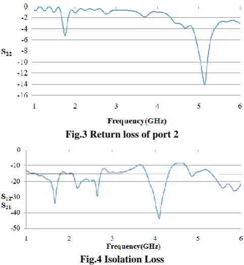
[image:4.595.308.546.55.239.2]Their S-parameter of port1 and port2 are based on horizontal polarisation and vertical polarisation.The Port 1 resonates at frequency of 2.162GHz, 3.704GHz and 4.402GHz. It covers applications of UMTS (1.885GHz - 2.2GHz), WiMax (3.3GHZ – 4GHZ) and C band (4GHz – 8GHz). The Port 2 resonates at frequency of 5.137GHz. It covers applications of WLAN (5 GHz – 6 GHz).The return loss of the frequencies is less than10dB.
Fig.3 Return loss of port 2
Fig.4 Isolation Loss
Figure4 displays the isolation loss among port 2 and port 1. The isolation loss between two ports should be less than 15dB. The isolation loss of only two resonant frequencies i.e., 2.162GHz and 5.15GHz is less than 15dB. It has the bandwidth of 28MHz and 173MHz.
VI. FOUR FEED RECTANGULAR PATCH Figure 5 displays the configuration of four feed rectangular patch antenna which is fed by 50Ω microstrip feed line. The detailed dimensions of the front view and back view of antenna is mentioned in Table 6.1. It uses the substrate as low cost FR4 epoxy with εr=4.3 at a height of 1.6mm. The antenna
is intended for the frequency of 2.4GHz and 5GHz. It has fed with four inset feed port. The feed line matches the characteristic impedance of 50Ω.
[image:4.595.304.548.281.332.2]Fig.5 Four feed rectangular patch
Table.4 Dimensions of four feed rectangular patch
6.1 Simulation Results and Discussion
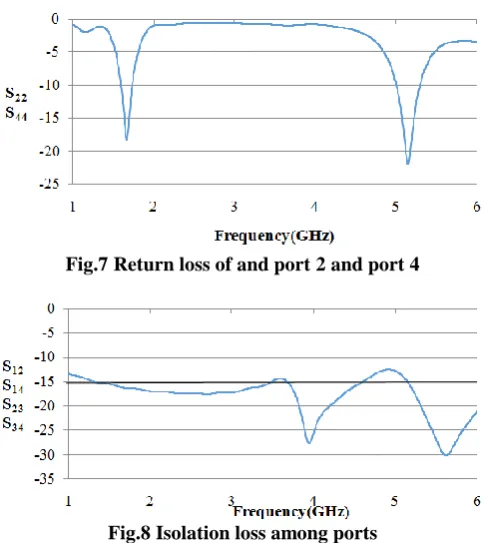
[image:4.595.48.289.305.566.2]The simulation outcomes of four feed rectangular patch antenna are as follows. The simulation results such as S-parameter response of return loss and isolation loss are discussed in this section. Figure 6 shows the return loss of horizontal polarisation ports i.e., port1 and port3. Figure 7 shows the return loss of vertical polarisation ports i.e., port 2 and port 4.
Fig.6 Return loss of port 1, port 3
[image:4.595.308.546.438.565.2]International Journal of Innovative Technology and Exploring Engineering (IJITEE) ISSN: 2278-3075, Volume-8 Issue-9, July 2019
[image:5.595.47.289.46.318.2]Published By: Retrieval Number: I8618078919/19©BEIESP
Fig.7 Return loss of and port 2 and port 4
Fig.8 Isolation loss among ports
[image:5.595.45.289.432.671.2]Figure 8 shows the isolation loss among ports.The isolation losses between two ports is less than 15dB. The isolation loss of all the resonant frequency is greater than 15dB. The isolation loss is very low. It has the bandwidth of 85MHz and 292MHz at the resonant frequencies 2.092GHz and 5.155GHz. Figure 9 shows the isolation loss between port 1 and port 3. Figure 10 shows the isolation loss between port 2 and port 4. The isolation loss is very low.
Fig.9 Isolation loss among port 1 and port 3
Fig.10 Isolation loss among port 2 and port 4 VII. CONCLUSION
The geometry and simulation results of the single element rectangular patch antenna with two feed and multiple feed are analysed by considering S-parameter of isolation loss and return loss. The results of the planned designs have -10 dB reflection coefficient, low correlation, high isolation between element, high gain and reduced dimension while integrating element in a single plane.
REFERENCES
1. R.V.S.R.Krishna et.al, "A Dual-Polarized Square-Ring Slot Antenna for UWB, Imaging, and Radar Applications," in IEEE Antennas and Wireless Propagation Letters, volume. 15, Issue no.2 , pp. 195-198, 2016.
2. C. H. Lee et.al., "Isosceles Triangular Slot Antenna for Broadband Dual Polarization Applications," in IEEE Tansactions on Antennas and Propagation, volume. 57, Issue no. 10, pp. 3347-3351, Oct. 2009. 3. D.D.Krishna et.al."Compact dual-polarised square microstrip antenna
with triangular slots for wireless communication," in Electronics Letters, volume. 42, Issue no. 16, pp. 894-895, August 3, 2006. 4. J.J.Xie et.al., "Wideband printed slot antenna with polarisation
diversity," in Electronics Letters, volume. 49, Issue no. 12, pp. 737-739, June 6 2013.
5. Hussein Hamed Mahmoud Ghouz, “A New Compact Two-Port
MicrostripAntenna,”inInternational Refereed Journal of Engineering and Science (IRJES), Volume 3, Issue 2 (February 2014), PP.87-93. 6. Cheong, P et.al., "A Highly Integrated Antenna-Triplexer With
Simultaneous Three-Port Isolations Based on Multi-Mode Excitation,"
IEEE Transactions on Antennas and Propagation, vol.63, no.1, pp.363-368, Jan. 2015.
7. Y. Li et.al., "A Dual-Polarization Slot Antenna Using a Compact CPW Feeding Structure," in IEEE Antennas and Wireless Propagation Letters, vol. 9, no. , pp. 191-194, 2010.
8. Kin-Lu Wong et.al., "Broadband dual-polarized patch antennas fed by capacitively coupled feed and slot-coupled feed," in IEEE Transactions on Antennas and Propagation, vol. 50, no. 3, pp. 346-351, Mar 2002. 9. QuanjiangZhu;Shiwen Yang et.al.,”Modified corner-fed dual-polarised
stacked patch antenna for micro-base station applications”,IEEE Electronics Letters Vol. 51, No. 8 pp. 604–606, 16th April 2015. 10. B.P.Chacko et.al., "Uniplanar polarisation diversity antenna for
ultrawideband systems," in IET Microwaves, Antennas & Propagation, vol. 7, no. 10, pp. 851-857, July 16 2013.
11. Lee, B et.al., "Polarisation diversity microstrip base station antenna at 2 GHz using T-shaped aperture-coupled feeds," in Microwaves, Antennas and Propagation, vol.148, no.5, pp.334-338, Oct 2001.
12. C.M.Luo et.al., "Isolation Enhancement of a Very Compact UWB-MIMO Slot Antenna With Two Defected Ground Structures," in IEEE Antennas and Wireless Propagation Letters, vol. 14, no. , pp. 1766-1769, 2015.
13. Younkyu Chung et.al., "High isolation dual-polarized patch antenna using integrated defected ground structure," IEEE in Microwave and Wireless Components Letters, vol.14, no.1, pp.4-6, Jan. 2004. 14. Jung-Hoon Han et.al.,” Novel Feed Network for Circular Polarization