ABSTRACT
SITZABEE, WILLIAM EMIL. A Spatial Asset Management Study Through an Analysis of Pavement Marking Performance. (Under the direction of Joseph E. Hummer and William J. Rasdorf.)
This research evaluates pavement marking performance characteristics of NC’s highways and proposes asset management guidelines that will enable NC to effectively implement new Federal standards. Predictive models were developed and used to forecast the performance of pavement markings retroreflectivity over time. Consideration was given to the analysis of the relationships between pavement marking retroreflectivity values and variables such as marking color, marking age, pavement surface, and lateral location. Understanding retroreflectivity performance over time facilitated the development and implementation of guidelines and tools that will be used for holistic asset management. The guidelines and tools enable pavement-marking managers to focus limited resources where they are most needed and avoid replacing materials with effective life still remaining. Additionally, this research provides a means for NCDOT to establish the condition state of pavement markings throughout the State of North Carolina. This can be used to determined if they will be in compliance with pending minimum retroreflectivity standards that the Federal Highway Administration is proposing to publish.
A Spatial Asset Management Study Through an Analysis of Pavement Marking Performance
by
William E. Sitzabee
A dissertation submitted to the Graduate Faculty of North Carolina State University
in partial fulfillment of the requirements for the Degree of
Doctor of Philosophy
Civil Engineering
Raleigh, NC 2008
APPROVED BY:
______________________________ ______________________________
Michael L. Leming, Ph.D. Hugh A. Devine, Ph.D.
Committee Member Committee Member
ii DEDICATION
iii BIOGRAPHY
iv ACKNOWLEDGMENTS
v TABLE OF CONTENTS
LIST OF FIGURES... vii
LIST OF TABLES ... viii
1.0 Introduction ...1
1.1 Problem ...2
1.2 Research Approach ...3
1.3 Research Objectives ...4
2.0 Background and Literature Review ...7
2.1 Asset Management ... 12
2.1.1 Federal Approach to Asset Management ... 12
2.1.2 Location Referencing ... 17
2.1.3 Geographical Information Sciences ... 17
2.2 Proposed FHWA Minimum Retroreflectivity Standards... 19
2.3 Evaluation of Current Retroreflectometer Technology ... 22
2.4 Pavement Marking Performance and Management ... 23
2.4.1 South Carolina Study ... 24
2.4.2 Washington State Study ... 29
2.4.3 Michigan Study ... 31
2.4.4 Migletz Study... 33
2.4.5 Iowa Study ... 36
2.4.6 Alabama (2002) ... 38
2.5 Literature Review Summary ... 40
3.0 Methodology For Pavement Marking Perfromance ... 41
3.1 Data Collection ... 41
3.1.1 Mobile Collection Device... 42
3.2 Data Organization ... 49
3.2.1 South Carolina Data Organization ... 49
3.2.2 North Carolina Data Organization ... 50
3.3 Data Analysis ... 62
3.3.1 Validation of Variables ... 62
3.3.2 Modeling... 67
4.0 Methodology for Asset Management ... 70
4.1 Goals and Policy Development ... 70
4.2 Assess, Develop, and Maintain an Asset Management Inventory ... 73
4.3 Pavement Marking Database Management and Modeling ... 74
4.4 Implementation Strategy ... 76
5.0 Results for Pavement Marking Performance ... 77
5.1 Markov Analysis ... 77
5.2 Variables ... 80
5.2.1 Explanation of Independent Variables ... 82
5.3 Models ... 95
5.3.1 Thermoplastics ... 95
5.3.2 Paints ... 109
5.4 Model Validation ... 114
vi
5.4.2 Comparison to Existing Models ... 116
5.4.3 Actual Verses Predicted plot of model data ... 118
5.4.4 Comparison of Predicted Values to Independent Sample ... 120
5.5 Summary of Results ... 123
6.0 Pavement Marking Asset management System ... 127
6.1 Goals and Policy Development ... 128
6.1.1 Asset Parameters ... 128
6.1.2 Governing Regulations for Pavement Marking ... 130
6.1.3 Overview of Finance and Budget Process ... 130
6.1.4 Pavement Marking Retroreflectivity Level of Service ... 133
6.2 Assess, Develop, and Maintain an Asset Management Inventory ... 140
6.2.1 Attributes for Performance Modeling ... 141
6.2.2 Attributes for Asset Management ... 145
6.2.3 Data Collection Plan ... 149
6.2.4 Pavement Marking Inspection and Data Collection Process ... 159
6.3 Pavement Marking Database Management and Modeling ... 163
6.3.1 Conceptual Model ... 164
6.3.2 Logical Model ... 165
6.3.3 Physical Model ... 167
6.3.4 Normalization ... 169
6.3.5 Data Model Diagrams ... 170
6.3.6 Algorithm ... 179
6.3.7 Demonstration ... 182
6.3.8 Asset Management Strategies ... 186
6.3.9 Sensitivity Analysis ... 187
6.4 Implementation of a Transportation Asset Management System ... 189
6.4.1 Measured Data ... 190
6.4.2 Condition Decision to Perform Queries and Develop Strategies ... 191
6.4.3 Limitations ... 193
6.4.4 Implementation ... 199
7.0 Conclusions ... 202
7.1 Performance Modeling ... 203
7.2 Asset Management ... 205
8.0 Recommendations ... 208
8.1 Limitations of the Current Research ... 209
8.2 Recommendations for Future Research... 209
9.0 References ... 214
10.0 Annotated Bibliography ... 219
APPENDICES ... 231
11.0 Appendix A ... 232
12.0 Appendix B ... 249
13.0 Appendix C ... 252
vii LIST OF FIGURES
Figure 2.1. Illustration of 4 Lane Primary Road Pavement Marking Lateral Location ...8
Figure 2.2. Basic Principles of Pavement Marking Retroreflectivity ... 10
Figure 2.3. 30-Meter Retroreflectivity Geometry ... 12
Figure 2.4. Retroreflected Raised Pavement Marking ... 20
Figure 2.5. Predictive Curve for Newly Placed Pavement Marking ... 27
Figure 2.6. Predictive Curve for Existing Pavement Markings ... 27
Figure 2.7. Predictive Curves for Remarking and Snowplowing ... 27
Figure 2.8. Pavement Marking Accepted Service Life Matrix ... 35
Figure 2.9. Iowa Longitudinal Pavement Markings Application Matrix ... 38
Figure 3.1. Vehicle Mounted Laserlux ... 43
Figure 3.2. Data Collecting Laser ... 44
Figure 5.1. Transition Matrices ... 79
Figure 5.2. Average RL Values Over Time of Yellow Thermoplastics (Un-weighted) ... 86
Figure 5.3. Average RL Values Over Time of White Thermoplastics (Un-weighted) ... 87
Figure 5.4. Average Value Over Time of Yellow Thermoplastics (Weighted)... 89
Figure 5.5. Average Value Over Time of White Thermoplastics (Weighted) ... 90
Figure 5.6. Consolidated Model Residual Plot of Predicted Values ... 99
Figure 5.7. Consolidated Model Residual Plot of Predicted Values ... 100
Figure 5.8. Consolidated Model Q-Q Plot ... 101
Figure 5.9. White Edge Residual Plot of Predicted Values ... 102
Figure 5.10. White Edge Q-Q Plot ... 103
Figure 5.11. White Middle Residual Plot of Predicted Values ... 104
Figure 5.12. White Middle Q-Q Plot ... 105
Figure 5.13. Yellow Edge Residual Plot of Predicted Values ... 106
Figure 5.14. Yellow Edge Q-Q Plot ... 107
Figure 5.15. Yellow Middle Residual Plot of Predicted Values ... 108
Figure 5.16. Yellow Middle Q-Q Plot ... 109
Figure 5.17. Residual Plot of the Predicted Values for Paints ... 111
Figure 5.18. Q-Q Plot for Residuals of Paints ... 113
Figure 5.19. Q-Q Plot for Log Transformed Residuals of Paints ... 113
Figure 5.20. Plot of Average RL Values Over Time... 115
Figure 5.21. Actual Verses Predicted Values for the Consolidated Thermoplastic Model .. 119
Figure 5.22. Actual verses Predicted with White and Yellow Thermoplastics ... 120
Figure 6.1. Presumed Pavement Marking Degradation Curve with LOS Increments ... 140
Figure 6.2. Pavement Marking Management System Conceptual Model ... 165
Figure 6.3.Pavement Marking Management System Logical Model... 166
Figure 6.4. Physical Database Management Model ... 171
Figure 6.5. Pavement Marking Database Schema ... 173
Figure 6.6. Pavement Marking Retroreflectivity Algorithm ... 180
Figure 6.7. I-95 Actual RL Values for Yellow Edge Pavement Markings ... 183
Figure 6.8. I-95 Actual and Predicted RL Values for Yellow Edge Pavement Markings .... 185
viii LIST OF TABLES
Table 2.1. Pavement Marking Materials in Use...9
Table 2.2. Recommendations for Minimum Retroreflectivity Values [Turner, 1998] ... 20
Table 2.3. Proposed State, County, and Local Minimum Retroreflectivity Standards ... 21
Table 2.4. Summary Table of Key Pavement Marking Performance Studies ... 24
Table 2.5. South Carolina Study Summary ... 29
Table 2.6. Washington Study Summary ... 31
Table 2.7. Michigan Study Summary ... 33
Table 2.8. Migletz Study Summary ... 35
Table 2.9. Iowa Study Summary ... 38
Table 2.10. Summary of Modeling Studies ... 40
Table 3.1. Segment Run Retroreflectivity Data Collection Flat File ... 46
Table 3.2. Run Instance Data Collection Flat File ... 47
Table 3.3. South Carolina Analysis Categories ... 50
Table 3.4. NC Analysis Categories; Step 1 for Asphalt ... 55
Table 3.5. NC Analysis Categories; Step 1 For Concrete ... 56
Table 3.6. NC Analysis Categories; Step 2 for Asphalt and Concrete ... 57
Table 3.7. NC Analysis Categories; Step 3 for Asphalt and Concrete ... 58
Table 3.8. NC Analysis Categories; Step 4 for Asphalt and Concrete ... 59
Table 3.9. NC Durable Categories Included in Research ... 59
Table 3.10. NC Categories, Non-durable for Future Research ... 60
Table 3.11. Summary of Available Data ... 60
Table 3.12. Summary of Available Data Non-Durables ... 60
Table 5.1. Effects Test for White Edge Using the F-Statistic... 81
Table 5.2. Average RL Values Over Time of Yellow Thermoplastics (Un-weighted) ... 87
Table 5.3. Average RL Values Over Time of White Thermoplastics (Un-weighted) ... 87
Table 5.4. Average RL Values Over Time of Yellow Thermoplastics (Weighted) ... 89
Table 5.5. Average RL Values Over Time of White Thermoplastics (Weighted) ... 90
Table 5.6. ANOVA F-test Results for White and Yellow Thermoplastics (Un-weighted).... 92
Table 5.7. ANOVA F-test Results for White and Yellow Thermoplastics (Weighted) ... 93
Table 5.8. Summary of Thermoplastic Retroreflectivity Degradation Models ... 97
Table 5.9. Consolidated Model Parameter Estimates... 98
Table 5.10. White Edge Parameter Estimates ... 102
Table 5.11. White Middle Parameter Estimates ... 104
Table 5.12. Yellow Edge Parameter Estimates ... 106
Table 5.13. Yellow Middle Parameter Estimates ... 108
Table 5.14. Paint Parameter Estimates ... 111
Table 5.15. Simple Statistics of the Pavement Marking Retroreflectivity Data ... 116
Table 5.16. Comparison of Degradation Rates and Service Life of Models ... 118
Table 5.17. Predictive Estimate Compared to Summary of Validation Data ... 122
Table 5.18. Summary of Thermoplastic Pavement Marking Service Life by Category ... 125
Table 6.1. LOS Increments and NC Minimum Retroreflectivity Standards ... 136
Table 6.2. Pavement Marking Installation Attributes for Asset Management ... 147
Table 6.3. Pavement Marking Time-based Retroreflectivity Attributes ... 148
ix
Table 6.5. NC Durable Categories Included in Research ... 157
Table 6.6. NC Non-durable Categories, for Future Research ... 158
Table 6.7. Process Input and Output for Pavement marking Algorithm ... 181
Table 6.8. Predicted RL and Cost Data for I-95 Halifax Example ... 187
Table 6.9. Simulator Parameter and Coefficient Estimate Values ... 188
Table 6.10. Summary of NC Initial RL Values ... 196
1 1.0 INTRODUCTION
An overall asset management strategy is necessary to successfully manage pavement marking retroreflectivity. The North Carolina Department of Transportation (NCDOT) is charged with managing all aspects of a 78,000-mile roadway system, which includes over 312,000 lane miles of pavement markings [Howard, 2006]. Pavement markings cost NC approximately $14.5 million a year in contractor-performed work which represents two percent of the $700 million NCDOT budget [Howard, 2006]. Strategic approaches to pavement marking management will not only ensure efficient use of a limited budget but will enable NCDOT to follow Federal guidance in asset management.
According to the Federal Highway Administration (FHWA), asset management is a strategic approach to managing physical infrastructure using cost-effective solutions based on sound engineering and business principles [Cambridge Systems, Inc., 2002]. Asset management should consider both short-term and long-term system needs using a holistic, life-cycle approach. NCDOT is taking steps to improve pavement marking infrastructure management in order to meet projected Federal minimum pavement marking retroreflectivity requirements. These steps include shaping their asset management strategy based on the guidelines and principles set forth in FHWA’s Asset Management Guide [Cambridge Systems, Inc., 2002].
2 retroreflectivity for pavement markings [United States Congress, 1993]. This Congressional directive applies to all roads that are open to the public. The Federal Highway Administration (FHWA) published 69 FR 45623 on 30 July 2004 and included directives for sign retroreflectivity but did not include the minimum required retroreflectivity for road pavement markings. Candidate minimum values for road pavement markings have been established [Turner, 1998], and the FHWA is expected to publish pavement marking retroreflectivity standards in the near future.
1.1 Problem
There are two aspects to this pavement marking research problem. First, the current management approach is not performance based which means that there is a potential for cost savings and increased service life for pavement markings. Second, there is a legislative requirement to implement pending Federal standards for minimum retroreflectivity values on all public roads.
3 The WZTCU requested that North Carolina State University (NCSU) develop a pavement markings research plan in order to analyze relationships between pavement marking retroreflectivity values and variables such as marking color, marking age, and pavement surface. NCSU did this and submitted its report in summer 2006 [Rasdorf et al., 2006]. The preliminary analysis outlined by NCSU aided the WZTCU to better understand pavement marking performance and enable the NCDOT to make cost-effective decisions with respect to this asset.
Understanding retroreflectivity performance over time is important to establishing a pavement marking strategy that maximizes the material’s lifecycle and minimizes replacement of pavement markings that still have sufficient retroreflectivity. On 1 July 2007 the NCDOT formalized the relationship and funded NCSU to research pavement marking degradation through NCDOT research project 2008-05 which is a $174, 800 two-year research grant (NCDOT, 2007). This research begins to implement the NCSU plan to manage pavement-markings from a holistic asset management approach.
1.2 Research Approach
This research follows a two-phase approach:
The first phase is to determine the performance characteristics of pavement markings in NC and create viable predicative models.
4 marking performance based on a specified set of given parameters. The developed GIS application will be used to formalize pavement marking management strategies and guidelines.
According to Migletz and Graham, several states are starting pavement marking management programs but none are fully developed [2002]. South Carolina and Iowa are working on developing pavement marking management systems and each have included some form of GIS into the foundation but none are fully developed [Sarasua, Clarke, and Davis, 2003; Hawkins, Samdi, and Hans, 2005]. Research that combines pavement marking predicted behavior with GIS applications is not only timely but will certainly enhance the fields of pavement markings and asset management. Ultimately, the goal of this research is to provide insight, establish a process, and develop techniques that can be expanded beyond pavement markings and used for the management of any continuous infrastructure system such as, Pavement condition, guardrails, drainage, and pipelines.
1.3 Research Objectives
The objectives of this research plan address both pavement marking material performance and pavement marking asset management. An appropriate set of work tasks, to meet each objective, is specified below.
Material Performance
Evaluate the retroreflectivity (RL) performance of pavement markings based on their
5 Determine rates, relationships, and correlations between analysis variables.
Predict the life of pavement markings, based on their deterioration rate and on FHWA/NCDOT minimum levels.
Asset Management
Develop goals and policies
Assess, develop, and maintain an asset inventory Database management and modeling
Implementation strategy development
In order for NCDOT to better understand the performance of different types of pavement markings, the deterioration of RL over time will need to be evaluated for a given set of
variables such a surface type, material type, location, and color. Once determined, the deterioration rates can be compared to existing rates already established in the Michigan State and Clemson studies. Correlations found between RL and other factors, such as traffic
levels and installation date, can be used by NCDOT to better predict when markings will need to be replaced.
7
2.0 BACKGROUND AND LITERATURE REVIEW
This literature review establishes a critical knowledge base explaining the impact of pavement marking retroreflectivity on a driver’s visibility. Specifically, this review compiles information on pavement marking retroreflectivity and how pavement markings perform over time. Understanding retroreflectivity performance over time is important to establishing a pavement marking strategy that maximizes the material’s lifecycle by minimizing replacement of pavement markings that still have sufficient retroreflectivity.
8 Figure 2.1. Illustration of 4 Lane Primary Road Pavement Marking Lateral Location
The objective of this literature search is to understand what has been done in the pavement markings field and to identify where critical research gaps exist. This review will cover governmental reports, legislation, periodic reviews, journal publications, conference proceedings, and expert interviews. This literature review covers the following topics:
Asset Management
9 Pavement marking retroreflectivity is a term used to describe the amount of light returned back to a driver from a vehicle’s headlights as it is reflected from the pavement marking. The light provides drivers with critical information about the road and enables the driver to navigate safely at night. Ultimately, retroreflectivity directly relates to driver safety.
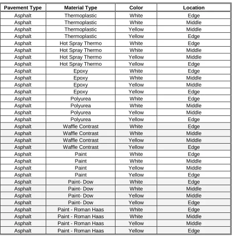
There are 16 types of line marking materials available on the market [Migletz and Graham, 2002]. Table 2.1 was adapted from Migletz and Graham [2002] and shows the 16 pavement marking materials in use. The majority of the materials are defined as durable pavement markings which mean pavement markings that are expected to last longer than one year. Waterborne and solvent based paints are considered nondurable pavement markings with a short service life of one year or less. According to the WZTCU, the NCDOT primarily uses four which are paint, thermoplastics, epoxy, and polyurea and are highlighted in Table 2.1.
Table 2.1. Pavement Marking Materials in Use
Pavement Marking Material Type Percentage of Use
1 Waterborne paint 59.9
2 Thermoplastics 22.7
3 Conventional solvent paint 6.5
4 Polyester 3.8
5 Epoxy 2.7
6 Preformed tape – flat < 1.0
7 Preformed Tape - profiled < 1.0
8 Methyl methacrylate < 1.0
9 Thermoplastics profiled < 1.0
10 Polyurea < 1.0
11 Cold applied plastics < 1.0
12 Experimental < 1.0
13 Green lite powder < 1.0
14 Polyester profiled < 1.0
15 Tape removable < 1.0
16 HD-21 < 1.0
10 Pavement marking materials provide a base line of retroreflectivity. However, the bulk of the retroreflectance is achieved through the addition of glass beads embedded into the pavement marking material. The glass beads significantly improve the retroreflectivity of the pavement marking material. Figure 2.2 shows the basic concept of retroreflectivity and how the light from a vehicle’s headlights is retroreflected off of a glass bead in the pavement marking back to the driver’s eye and is adapted from ASTM standards [ASTMa, 2005].
Figure 2.2. Basic Principles of Pavement Marking Retroreflectivity
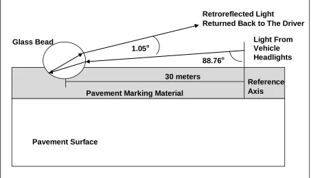
ASTM standard number E1710-05 specifies that pavement marking retroreflectivity should be determined by measuring the amount of light returned from a pavement marking when a handheld device (using 30-meter geometry) directs light at the pavement marking at an entrance angle of 88.76 degrees measured from the reference axis which is a perpendicular line from the pavement surface. The returned amount of light is measured at an observation
Pavement Surface
Light From Vehicle Headlights Retroreflected Light
Returned Back to The Driver
1.05o Glass Bead
30 meters 88.76o
11 angle of 1.05 degrees which is the angle measured from the difference of the vehicle’s headlight back to the drivers view from a point 30 meters in front of the vehicle [ASTMa, 2005].
The standard used to measure retroreflectivity of pavement markings is the coefficient of retroreflected luminance (RL) in units of millicandles/m2/Lux (mcd/m2/lx) [ASTMa, 2005].
ASTM E 1710-05 describes the testing standards using portable retroreflective measurement devices [ASTMa, 2005]. Current ASTM standards require a specific geometry commonly called 30-meter geometry. The basis behind 30-meter geometry is to measure the retroreflectivity at a point 30 meters ahead of a vehicle. The angle of 1.05o is the difference required for light to reflect back from the headlight to the driver’s field of vision based on a spot 30 meters in front of the driver’s vehicle. This is believed to be the point at which most drivers observe the roadway at night.
12 Figure 2.3. 30-Meter Retroreflectivity Geometry
2.1 Asset Management
This section discusses a seven-step approach to asset management endorsed by the FHWA. Presented next is a discussion on the current literature dealing with spatial concepts specifically, the use of linear referencing in transportation networks. Finally, this section introduces geographical information systems as a means of modeling transportation systems.
2.1.1 Federal Approach to Asset Management
According to the FHWA, asset management is a cost effective approach to systematically maintain, upgrade and operate a physical asset. The process combines engineering principles with sound business practices and economic theory for the purpose of improving decisions [FHWA, 1999]. A pavement management system is considered the backbone of transportation asset management and has long been considered a tool for collecting and monitoring information [FHWA, 1999]. Three principal components to a pavement management system are (1) data collection and management, (2) analysis, and (3) feedback
Receiver
Reference Axis
Observation Angle
Entrance Angle
Illumination Axis
Observation Axis
13 to the system. Each component is part of the process to manage the current pavement as well as forecast future conditions to evaluate and prioritize alternatives for maintenance, rehabilitation, and new construction [FHWA, 1999].
The FHWA Asset Management Guide states that the key aspect to asset management is to organize project priority based on measurable objectives established from well-defined goals. This approach is the defining aspect of the recommended FHWA asset management [Cambridge Systems Inc., 2002] approach and includes:
1) Develop goals and policies
2) Perform and maintain an asset inventory
3) Perform a condition assessment and conduct performance modeling 4) Alternative evaluation and program optimization
5) Develop short and long range plans (project selection) 6) Performance monitoring
7) Program implementation
14 performance and create models of the system that will enable mangers to predict future conditions. The fourth step is to create alternatives to system projects and optimize those alternatives to produce the best projects for the system based on performance and sound business practices. The development of alternatives can lead to the development of short and long range plans and enable managers to effectively choose the right alternative. The next step, step six, is to monitor the performance of the chosen alternative. Finally, step seven is to implement the program and monitor feedback so that goals and policies can be adjusted accordingly.
NCHRP Report 551, Performance Measures and Targets for Transportation Asset Management, provides an update to the transportation asset management principles and further guidance on the development and implementation of performance measures and targets used for asset management [Cambridge Systematics, Inc., 2006]. The backbone to this asset management approach is a performance-based framework for decision makers that transcend all levels of the organization both horizontally and vertically [Cambridge Systems Inc., 2006].
The five key principles for the performance-based asset management approach [Cambridge Systems Inc., 2006], are:
15 2. Performance based – Goals and objectives must be tied to clear measures of performance.
Targets established for these performance measures will guide decision makers through the analysis of options, setting of priorities, and program budgeting and implementation. 3. Analysis of options and tradeoffs – Consideration of options and evaluating the tradeoffs
among alternatives is caused by competition for scarce resources and interrelationships among decision makers.
4. Decisions based on quality information – Choices among options during program development, project selection, and program and service delivery are based on their relative costs and consequences in meeting performance targets. Objective, high-quality information is applied at each step, using analytical methods and decision criteria that are consistent with policy goals and objectives and an agency’s business processes.
5. Monitoring to provide clear accountability and feedback - Performance measures are monitored and reported, providing feedback on effectiveness of transportation investments and services, work accomplished, and program and service delivery.
16 decided. Furthermore, is summarizes the impact and consequences across the organization and on the overall function of the asset. The next two principles call for quality information and feedback. Realistically, these principles need to be carried throughout the entire process.
NCHRP Report 551 highlights the need for quality information, including the use of scientific methods to collect and analyze data. Collecting inventory data can be time consuming and costly. The use of statistical methods to estimate the condition of the asset is one way the document recommends of providing quality information yet minimizing data collection costs.
To date no studies have been identified that match asset management concepts with pavement marking performance. Specifically, there have not been any performance models of pavement markings, a step identified in the FHWA asset management process, that have been incorporated into an overall pavement management system. Iowa developed an application matrix that provides guidance for pavement marking applications [Hawkins et al., 2005]. Iowa has only completed phase one of three and is still working on developing operational tasks and implementation strategies to implement the matrix into a comprehensive pavement management system [Hawkins et al., 2005].
17 [2005] argue that models of pavement marking and marker visibility are a critical research gap in pavement marking performance.
2.1.2 Location Referencing
Location referencing systems (LRSs) consist of techniques and procedures for accurately collecting, storing, maintaining, and retrieving location information [Flintsch et al., 2004]. Pavement management systems typically use a location referencing system known as linear referencing. This is particularly useful in transportation networks because of the ability to accurately locate most transportation features, including pavement markings, in a one-dimensional way throughout a link-node network system [Flintsch et al., 2004]. Additionally, LRSs are easily integrated into most GIS applications.
The increased use of GIS technologies and automated data collection equipment has increased the use of GPS as a location referencing method [Flintsch et al., 2004]. In a nation wide survey of DOT’s, 35 percent of agencies surveyed indicated they used a GPS based latitude and longitude location referencing system. An additional 13 percent indicated they used a GPS based state plane coordinate system. Most agencies indicated that the inclusion of GPS technology was not the sole LRS used and that linear referencing methods were still used in conjunction with the GPS based LRS [Flintsch et al., 2004].
2.1.3 Geographical Information Sciences
18 maintained in different areas within a DOT and are most often compatible. The power of a GIS is the ability of a user to integrate information from various sources and spatially connect that information to identify aspects of the transportation system that would otherwise be unapparent [Flintsch et al., 2004].
Ontology is a description of concepts and relationships that can exist for a domain [Gruber, 1993]. The basic premise is to define the domain in terms of elements such as objects, classes, attributes, and relationships, with semantics that can be interpreted by both humans and machines [Weng and Chang, 2007]. Ontology provides the basic building blocks for developing a data model and provides humans with a framework for interacting with application systems by providing a representation about a domain in a form of components [Weng and Chang, 2007].
Longley et al. state that a data model is a set of constructs for representing objects and processes in the digital environment [Longley et al., 2005]. The model enables a user to simplify the real world to perform meaningful analysis on complex systems. Decisions about the type of data model to use are strongly influenced by types of analysis expected and the level of information available or needed to fully understand the complexity of the system modeled [Longley et al., 2005]. Defining the data model with ontologies takes humanistic definitions about the system and applies semantics that enable the model to interact with a given application [Weng and Chang, 2008].
19 major components that influence the system. Second is the development of a conceptual model, which is a human-oriented, often partially structured, model of selected objects and processes that are thought relevant to a particular problem domain. Third is the development of a logical model, which is an implementation-oriented representation of reality that is often expressed in the form of diagrams and list. Finally, the physical model portrays the actual implementation in a GIS and often comprises tables stored as files or databases.
2.2 Proposed FHWA Minimum Retroreflectivity Standards
The FHWA has developed a proposed set of minimum pavement marking retroreflectivity standards [Turner, 1998]. The candidate standards are summarized in Table 2.2. The proposed standards remain unpublished since the FHWA is awaiting recommendations from an American Association of State Highway and Transportation Officials (ASSHTO) retroreflectivity task force before proceeding with the publication [Hawkins, 2000].
The proposed standards are set up as a matrix that accounts for three major variables. First, the matrix is divided into three option fields based on the type and speed of the roadway. The three options will need to be reduced to a single definition of the roadway classification and speed before publication. Second, the matrix separates roadways with and without retroreflected raised pavement markings (RRPMs). Figure 2.4 shows a picture of an RRPM. Finally, the matrix separates the standards based on color, either white or yellow.
20 Table 2.2. Recommendations for Minimum Retroreflectivity Values [Turner, 1998]
Option 1 Non-Freeway
≤ 45 mph
Non-Freeway
≥ 45 mph
Freeway
≥ 55 mph
Option 2 ≤ 40 mph ≥ 45 mph ≥ 60 mph and
≥ 10,000AADT
Option 3 ≤ 40 mph 45 – 55 mph ≥ 60 mph
With RRPM White 30 35 70
Yellow 30 35 70
Without RRPM White 85 100 150
Yellow 55 65 100
Note: Retroreflectivity values are mcd/m2/lux and measured with 30-m geometry RRPMs – Retroreflective Raised Pavement Markers.
Figure 2.4. Retroreflected Raised Pavement Marking
21 differences from the Federal proposal are seen in this proposal. First is the introduction of the concept of presence markings, which are pavement markings with no requirement for retroreflectivity. Second, there is no need for retroreflectivity values on roads with raised retroreflectivity markers.
Table 2.3. Proposed State, County, and Local Minimum Retroreflectivity Standards
Material Color Local & Minor
Collector (30 mph)
Major Collector & Arterial (35-50 mph)
Highways, Freeways, and All Roads
(>55 mph)
White Presence 80 100
Yellow Presence 65 80
Note: Retroreflectivity values are mcd/m2/lux and measured with 30-m geometry
22 2.3 Evaluation of Current Retroreflectometer Technology
There are both objective and subjective evaluation systems in use today to measure retroreflectivity of pavement markings. Objective measurements use retroreflectometers (mobile or handheld) while subjective evaluations are done through visual inspections by a trained observer. Both approaches are viable because there is no nationally calibrated standard for measuring retroreflectivity in the United States [Migletz and Graham, 2002]. In order to calibrate instruments and evaluate the accuracy of the measurements a national standard must be determined and this is a key to successfully developing minimum pavement marking retroreflectivity values [Migletz and Graham, 2002].
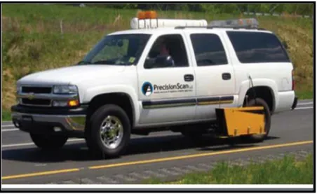
Six retroreflectometers were evaluated by the Highway Innovative Technology Center (HITEC) and represent the six leading units used by transportation agencies [Texas Transportation Institute, 2001]. Four of the six units were handheld devices and two were mobile units. All the units that were evaluated used 30-meter geometry to measure retroreflectivity. The Mirolux 12 was also evaluated but was left out of this summary because it uses 15-meter geometry, which is no longer acceptable under ASTM standards. The four handheld units evaluated were LTL 2000, MX30, MP-30, and FRT01. The two mobile units evaluated were the ECODYN and the Laserlux.
23 unit would be best to purchase for that agency. Ultimately, any of the six retroreflectometers mentioned would produce viable results [Texas Transportation Institute, 2001].
Handheld verses mobile collection methods each have advantages and disadvantages as well. The handheld units are inexpensive but require a large crew for safety reasons in order to collect a small number of samples. Mobile devices are significantly more expensive but provide for a safer collection method and can collect continuous data throughout the system at highway speeds.
2.4 Pavement Marking Performance and Management
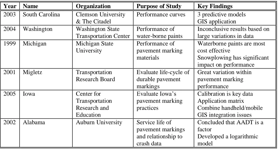
24 Table 2.4. Summary Table of Key Pavement Marking Performance Studies
Year Name Organization Purpose of Study Key Findings
2003 South Carolina Clemson University & The Citadel
Performance curves 3 predictive models GIS application 2004 Washington Washington State
Transportation Center
Performance of water-borne paints
Inconclusive results based on large variations in data 1999 Michigan Michigan State
University
Performance of pavement marking materials
Waterborne paints are most cost effective
Snowplowing has significant impact on performance 2001 Migletz Transportation
Research Board
Evaluate life-cycle of durable pavement markings
Great variation within pavement marking performance 2005 Iowa Center for
Transportation Research and Education Evaluate Iowa’s pavement marking practices
Calibration is key data Application matrix Combine handheld/mobile GIS integration issues 2002 Alabama Auburn University Service life of
pavement markings and relationship to crash data
Concluded that AADT is a factor
Developed a logarithmic model
2.4.1 South Carolina Study
25 The project was focused on SC interstate highways and evaluated pavement marking retroreflectivity performance during a 28-month period. Data were collected 6 times at over 150 sites throughout SC’s interstate system. An average value was established for each site from a series of 11 measurements taken with an LTL-2000 at each data collection site for each collection interval. Other devices were used during the research but only the data from the LTL-2000 was used in the analysis. Furthermore, the data were collected using 30-meter geometry, which is the required geometry identified in ASTM E 1710-97.
During the data analysis portion of the research, retroreflectivity performance was based on four major independent variables: surface type, marking material, marking color, and maintenance activities. Each variable was analyzed using regression analysis and was compared to the dependent variables. The dependent variables were the differences in retroreflectivity values and the percent differences in retroreflectivity values. Several other variables were considered but only these four were determined statistically to be viable independent variables that affect the performance of pavement markings over time. Traffic volume was one variable that was initially thought to impact performance but was later eliminated. Traffic volume was inversely correlated to the dependent variables and was adequately accounted for within the aspects of the variable time.
26 The first model, shown in Figure 2.5, demonstrates that the retroreflectivity of new pavement markings increased non-linearly during some initial time period after installation [Sarasua et al., 2003]. This was due to a greater number of reflective beads being exposed as the marking began to initially wear. After this initial time period, retroreflectivity was found to decrease linearly over time with a slight asymptotic curve at the end.
The second model, shown in Figure 2.6, was for existing pavement markings [Sarasua et. al., 2003]. The initial value of the retroreflectivity was typically lower than for new markings and there was a noticeable absence of the upward increase in retroreflectivity values.
27 Figure 2.5. Predictive Curve for Newly Placed Pavement Marking
Figure 2.6. Predictive Curve for Existing Pavement Markings
Figure 2.7. Predictive Curves for Remarking and Snowplowing
Time RL
Time RL
Time RL
Time RL
28 Additionally, SC developed two types of models for each combination of pavement marking material, surface material and color. One model was non-linear and represented the initial “break-in” period. The initial, non-linear model, calculates the number of days it takes for the material to rise and fall back to the original retroreflectivity value. The second model was linear and represented the degradation characteristics of the pavement marking retroreflectivity and starts when the initial value has risen and fallen back to the initial retroreflectivity value.
SC developed the models based on two different types of dependent variables. This first was the difference in retroreflectivity values over time which is the absolute difference in retroreflectivity values. The second was a percent difference in retroreflectivity values over time, which is the percentage of change in values over time. The models were developed for thermoplastics and epoxy. The thermoplastics on asphalt models are:
For White Thermoplastics: Diff = -0.06*(Days) –6.80 R2 = .47 (2.1)
% Diff = -0.03*(Days) – 3.29 R2 = .39 (2.2)
For Yellow Thermoplastics: Diff = -0.03*(Days) –3.63 R2 = .21 (2.3)
% Diff = -0.02*(Days) – 2.35 R2 = .24 (2.4) Where
29 % Diff = Percentage of difference in retroreflectivity over time
Days = Time in days
The end of service life for this model was defined by reaching a retroreflectivity value of 100 mcd/m2/lx
Table 2.5. South Carolina Study Summary
Objective Evaluate the effective life cycle of pavement marking retroreflectivity over time and create predictive models
Important Parameters
Study was complete in 2003. Evaluate interstates highways only.
Data were collected for 150 sites over a 28 month period. Study used an LTL-2000 handheld device with 30-m geometry.
Introduced dynamic segmentation to manage attribute information in a GIS.
Key Findings Three basic shapes represent performance of pavement marking retroreflectivity.
Developed two mathematical models based on difference of retroreflectivity and percent difference of retroreflectivity.
Snow plowing and remarking have significant impact on performance characteristics.
Mobile collection devices are efficient because they use continuous readings to collect large amounts of data and are safer to use. Handheld units are more accurate and cost less but are less efficient since they cannot collect large amounts of data.
Sources: [Thamizharasan et. al., 2002; Sarasua et. al., 2003]
2.4.2 Washington State Study
30 threshold value to indicate satisfactory performance [2004]. This value was arbitrarily specified based on the literature review performed by Kopf [2004].
Similar to the methodology used by NCDOT, Washington used the Laserlux mobile collection device because of the ability to safely and efficiently collect a large amount of data in a small period of time. The device was mounted on a 1995 Chevrolet Beauville van. The collection speed was 60 mph or the posted speed limit and collected a scan width of 1.1 meters. The device collects over 1500 measurements per mile and uses an onboard computer to calculate the average retroreflectivity every 250 feet. This distance was set by the user and was used to calculate the overall average retroreflectivity value for the entire test section. Linear referencing was used to designate the location of each test site and a GPS tag was captured, providing latitude and longitude coordinates for the test sample.
Regression analysis was used to fit curves to the data and determine the overall degradation of the pavement markings. The results were statistically inconclusive. The standard deviation in values was quite large and the variations in the data were too large for any curves to reasonably be fitted to the data.
31 remarking with paint based on an annual schedule and remarking heavy use areas twice a year.
Table 2.6. Washington Study Summary
Objective Develop retroreflectivity degradation curves for roadway pavement markings
Important Parameters
Study was completed in 2004.
Data were collected from 80 test sites throughout a 1-year period. Used a mobile collection device (vehicle mounted Laserlux). Study was primarily focused on waterborne paints.
Minimum acceptable retroreflectivity threshold was set at 100 mcd/m2/lux.
Key Findings Variation in the data resulted in inconclusive results.
Variations were attributed to data collection issues, including calibration of collection devices and repeatability due to precision of the location referencing. Washington should continue to remark with paint at least once a year and twice a year in heavy use areas.
Source: [Kopf, 2004]
2.4.3 Michigan Study
Michigan State University evaluated the performance of several pavement-marking materials in the mid 90’s [Lee et al., 1999]. The purpose of the study was to provide insight and guidance to implement cost effective procedures for pavement marking management. Focused on four major marking materials (paints, thermoplastics, thermosets, and tapes) the study used 50 sample sites throughout Michigan. The research objective was to determine the degradation rates for the various materials. A minimum threshold value of 100 mcd/m2/lux was used to indicate satisfactory marking performance.
32 This study attempted to establish a service life for marking materials. However, large variances in the extent of the material service life were shown and a clear explanation of what caused the large variance was not given. Time limitations minimized the amount of temporal data that were collected for each site, which could be a contributing factor. The degradation rates were deemed linear, but the R2 values ranged from 0.14 to 0.18 which are extremely low, showing little confidence that linear degradation was the best fit. Shown below is the model developed for thermoplastics which is:
RL = -0.3622*X + 254.82 R2 = 0.14 (2.5)
Where
RL = Retroreflectivity of pavement marking and
X = Age of the pavement marking in days
The end of service life for this model was defined by reaching a retroreflectivity value of 100 mcd/m2/lx.
33 did not justify the improved service life. Michigan is a high snowfall (snow plowing) state. Therefore, cost comparisons to a low snow plowing state like N.C. may not be wise.
Table 2.7. Michigan Study Summary
Objective Develop retroreflectivity degradation rates for roadway pavement markings
Important Parameters
Study was completed in mid-90’s. Data were collected from 50 test sites.
Used a handheld collection device (Mirolux with 12-meter geometry). Study focused on paints, thermoplastics, thermosets, and tapes.
Minimum acceptable retroreflectivity threshold was set at 100 mcd/m2/lux.
Key Findings Data included large, unexplained, variations in the retroreflectivity values.
Handheld device (12-meter geometry) showed many drawbacks.
Basic conclusion is that waterborne paint is most cost effective for high snowplow states.
Source: [Lee, 1999]
2.4.4 Migletz Study
Conducted by the Transportation Research Board using the Laserlux mobile retroreflectometer with 30-meter geometry, this study took place from 1994 to 1998 [Migletz et al., 2001]. Its purpose was to evaluate the life of durable pavement markings. Included in the study as a benchmark, was some limited evaluation of waterborne paints. The research collected data on 362 longitudinal (edge, center, & lane) pavement-marking lines from 85 sites across 19 states.
The Migletz study used regression analysis to evaluate various materials and establish a predictive degradation curve of the material performance over time. Marking material type, road surface type, and marking material color where the independent variables evaluated.
34 region of the country, marking specifications, quality control, and winter maintenance. No discussion was provided regarding the current age of the pavement markings when the study was performed. Furthermore, analysis indicated that yellow lines performed better than white but this was attributed to the use of a lower threshold of material expectations rather than on superior performance.
In a follow up study, Migletz et. al. (unpublished 2000) established an accepted service life matrix that provides degradation rates sorted by cumulative traffic passages (CTP) and elapsed months. The matrix in Figure 2.8, is an adaptation of Migletz’s matrix and shows the average service life for each material type in months.
The matrix is sorted by line color and type of marking material and provides an average service life and standard deviation in months. Additionally, the matrix gives a service life range in months. The two most common pavement marking materials are:
Ave Life of Waterborne paint is 10.4 months (white)
Ave Life of Thermoplastics is 26.2 months (white) and 27.5 months (yellow)
35
Material No of
Pavement Marking
Lines
Service Life In Elapsed Months Combined Cost Average Standard
Dev
Range $/Linear-ft
White Lines
Waterborne Paint 3 10.4 7.3 4.1 –18.4 0.06
Epoxy 18 23 17.1 1 - 56 0.26
Methyl methacrylate 7 14.4 7.6 6.8 – 29.3 1.22
Methyl methacrylate Profiled
9 21 13.4 7.8 – 43.2 1.44
Polyester 5 24.7 7.9 14.7 – 34.1 0.13
Polyester - Profiled 1 45.9 - 45.9 – 45.9 2.33
Thermoplastics 19 26.2 14.1 7.4 – 49.7 0.32
Thermoplastics - Profiled
14 23.8 12.8 4.7 – 55.7 0.87
Preformed Tape 11 27.4 13.6 11.7 – 60.0 1.41
Yellow Lines
Epoxy 15 34.3 14.6 12.6 – 57.8 0.26
Methyl methacrylate 4 16.8 4.2 12.6 – 20.5 1.22
Methyl methacrylate Profiled
5 25.0 6.0 18.1 – 32.8 1.44
Polyester 2 43.8 5.8 39.7 – 47.9 0.13
Polyester - Profiled 1 39.6 - 39.6 – 39.6 2.33
Thermoplastics 10 27.5 12.1 11.0 – 41.6 0.32
Thermoplastics - Profiled
8 26.7 10.3 17.8 – 50.7 0.87
Preformed Tape 7 30.6 11.9 19.6 – 53.4 1.41
Adapted from Migletz et. al. (unpublished 2000), Sites Without Roadway Lighting and RRPM
Figure 2.8. Pavement Marking Accepted Service Life Matrix Table 2.8. Migletz Study Summary
Objective Develop retroreflectivity degradation rates for roadway pavement markings
Important Parameters
Study was from 1994-1998.
Data were collected from 85 sites across 19 states.
Used a mobile collection device (Laserlux with 30-m geometry). Study focused on various durable pavement markings.
Key Findings Large variations in the shape of the degradation curves.
Regional changes influenced the shape of the curve for identical materials, and line type.
Matrix of service life degradation rates established based on unpublished data. Average Life of waterborne paint is 10.4 months.
36 2.4.5 Iowa Study
This project was the first phase of a multi-phase research program to evaluate the Iowa DOT pavement marking practices [Hawkins et al., 2005]. The project used retroreflectivity measurements to establish an application matrix based on material performance. The matrix included type of roadway, remaining service life, speed limits, traffic volume, and marking material. Phase two of this project is ongoing.
The Iowa DOT has one Lazerlux van, which is used to take continuous measurements of retroreflectivity throughout Iowa. The van is equipped with a 30-m geometry Laserlux retroreflectometer and collects data at a highway speed of 55 mph. The data collection uses a linear referencing system to collect location information and averages the retroreflectivity value for every tenth of a mile throughout the road segment. Each segment is then averaged over a specific route using the mileposts to mark the beginning and end of the route. GPS data are collected for each run and are recorded as attribute data. Standard linear referencing, based on milepost markings and offsets, was used to identify the location of each road segment.
Each of Iowa’s six districts has a Delta LTL-X handheld retroreflectometer, which is used during ongoing pavement-marking operations as a means of ensuring quality control. The LTL-X is also capable of 30-m geometry and collects GPS data for each site measured.
37 once a day or when erratic values were observed. The calibration process enabled the researchers to accommodate different temperature and humidity changes from day to day.
GPS data were collected for each test section. Significant issues were encountered when combining GPS data and the linear referencing system into a common GIS. The GPS data did not line up exactly with county referencing information already in the GIS. Additionally, changing route numbers at county borders created frustrations in organizing the data. Data from the mobile device were translated directly into a spreadsheet whereas the data from the handheld device were formatted through an additional program called CITRIX [Hawkins et al., 2005].
The first phase of this research project was considered successful in the development of the application matrix, shown in Figure 2.9 [Hawkins et al., 2005]. The matrix provides technicians with a practical approach to pavement marking management based on a given set of variables. The matrix provides a marking material for the given combination of road classification and number of service life years remaining.
38 Pavement
Surface Life
Primary 2 & 3 - Lane
Primary 4+ - Lane Interstate
Rural + Urban 55 mph
Rural Urban
High Traffic
< 50,000 AADT
> 50,000 AADT
< 2 yrs Waterborne Waterborne Durable WB
Waterborne
Waterborne Durable WB
3 – 5 yrs Durable WB Durable WB
Waterborne
Durable WB Waterborne Epoxy Polyurea
Durable WB Durable WB Polyurea Epoxy
5+ yrs Durable WB
Waterborne Epoxy Polyurea Durable WB Waterborne Epoxy Polyurea Durable WB Epoxy Polyurea Tape Durable WB Epoxy Polyurea Tape Durable WB Epoxy Polyurea Durable WB: durable waterborne paints
Adapted from Hawkins, et. al., 2005
Figure 2.9. Iowa Longitudinal Pavement Markings Application Matrix Table 2.9. Iowa Study Summary
Objective Evaluate Pavement Marking Practices
Important Parameters
Study was for a 12-month period.
Used both mobile and handheld collection devices (Laserlux with 30-m geometry and the LTL-X).
Combined GPS data with tradition linear referencing to locate test sites in a GIS.
Key Findings Developed application matrix based on material performance.
Calibration of collection equipment was key to good data. Combined use of mobile and handheld equipment to collect data.
Combining mobile and handheld units created integration issues when populating a GIS with location referencing information.
Sources: [Hawkins, et. al., 2005]
2.4.6 Alabama (2002)
39 Unique to this model is the use of VE as an independent variable, where VE is a function of the combination of time and AADT together. Also unique to this model is the absence of marking color and surface material, which have been established as independent variables for pavement marking degradation in other key pavement marking degradation studies. The degradation model presented in this research was for white thermoplastics edge lines and is presented below. A model for paints is also presented below. In each case pavement marking life and AADT were substituted with VE.
For Paint:
RL = -19.457*ln(VE) + 26.27 R2 = 0.31 (2.6)
For White Thermoplastic Edge Lines:
RL = -70.806*ln(VE) + 639.66 R2 = 0.58 (2.7)
Where
RL = pavement marking retroreflectivity (mcd/m2/lx) ln = natural logarithm, and
VE = Vehicle exposure which is: VE = AADT * PM_age *0.0304 AADT = Average Daily Traffic per lane
PM_age = age in months
40 2.5 Literature Review Summary
This literature review established the knowledge base and explained what has currently been done in the field of pavement marking. The review summarized the FHWA asset management approach, the status of the proposed Federal standards, a review of retroreflectivity data collection technology and a summary of six studies that focused on pavement marking performance. Five of the six studies created models. Table 2.10 shows a summary of the five studies and gives the type of each model. These studies show a significant difference in the degradation models. Three of the five studies concluded that pavement markings degrade linearly while two concluded they follow a logarithmic decay.
Table 2.10. Summary of Modeling Studies Research
Sponsor
Year Author Model Type R2 Marking
Material NCHRP 1997 Andrady Logarithmic Unavailable Unavailable
MSU 1999 Lee et al Linear 0.14 Thermo
TRB 1999 Migletz Linear Unavailable Paint & Thermo Alabama DOT 2002 Abboud &
Bowman
Logarithmic .31 - .58 Paint & thermo SCDOT 2003 Sarasua et.al. Linear .21 - .47 Thermo
TRB: Transportation Research Board, Thermo: thermoplastics
41
3.0 METHODOLOGY FOR PAVEMENT MARKING PERFROMANCE
This section presents the methodology used for analyzing pavement marking performance. First, the data collection process in presented. Next, the data organization is discussed. Finally, the analysis process used is presented.
3.1 Data Collection
Using a contractor, NCDOT personnel collected retroreflectivity data via a mobile device because of the ability to collect a large amount of data in a safe and efficient manner. This study took place from June 1999 through June 2006 and collected nearly 30,000 lane miles of data throughout N.C. The use of a contractor enables NCDOT to use state of the art equipment and experienced personnel without having to purchase equipment or permanently hire qualified personnel. NCDOT believed that eliminating the ability for a technician to choose a specific spot, such as commonly done with a handheld device, ensured the collection remained objective [McDiarmid, 2001].
In June of 1999 NCDOT hosted a field evaluation of various retroreflectivity collection devices. During the evaluation NCDOT personnel determined that the Delta LTL 2000 was the best handheld unit and that the LaserLux was the best mobile collection device for collecting retroreflectivity data on NC’s roads [McDiarmid, 2001].
42 ASTM standards for using a handheld device; there are no published ASTM standards for measuring retroreflectivity using a mobile collection device.
3.1.1 Mobile Collection Device
The data collection for this research used the Laserlux vehicle mounted mobile collection device calibrated with an LTL 2000 handheld device. This section explains the use of the mobile collection device. First, the vehicle and instrument are presented. Next, the data files are discussed. Third, the location referencing system is introduced. Finally, the calibration process is presented.
3.1.1.1 Vehicle and Data Collection Instrument
43 Figure 3.1. Vehicle Mounted Laserlux
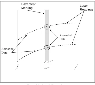
The retroreflectometer collected data using the standard 30-meter geometry by applying a 1/3 scale that measures approximately 10-m ahead of the vehicle. Figure 3.1 shows how a scanning laser measured a 42” wide swath that collected retroreflectivity values at a rate of 100 readings per second at a speed of 60 miles per hour. This equates to approximately 600 data points for a tenth mile road segment, which in turn translates to approximately 1 data reading for every 11 inches. The computer was set to collect values only within a given RL
44 42”
4”
Laser Readings Pavement
Marking
Recorded Data
Removed Data
Figure 3.2. Data Collecting Laser
The dashed lines in Figure 3.2 illustrate the collection path of the laser as the vehicle travels down the road segment (upward in the figure) and the laser sweeps across the pavement (shown as left to right in the figure) collecting retroreflectivity values. The dashed lines are arced because the laser swings from one side to the other while the vehicle is traveling at highway speeds. The laser then resets and starts the next collection sweep from the same side proceeding in the same direction for each sweep.
The RL readings are averaged for every tenth of a mile and recorded into the onboard
45 segment using all the valid data points that were determined to lie on the pavement marking. The RL value is an average of all the valid scans recorded for a tenth-mile road segment. For
a tenth-mile road segment there were approximately 600 data points evaluated but nearly 83 percent of the data are rejected because these values fell outside the preset range. This ensured only RL values for pavement markings were recorded and not the background RL for
the road surface or for raised reflective pavement markers.
The vehicle was set up so that a single person can operate the vehicle and collect the data simultaneously. The operator was able to record any significant events using an event recorder that adds pre-designated codes to the data fields of the roadway segment. Significant events are those that might affect the meaning or interpretation of the data. Examples of event codes are roadway construction, intersections, or new paint. In addition to inputs from the Laserlux instrument and operator, a vehicle-mounted video camera recorded the entire data collection run for each segment. There is also a GPS device mounted in the vehicle and integrated into the onboard computer, which records the position data in the database at appropriate intervals.
46 mcd/m2/lx. Establishing the most appropriate value to record (high value, low value, or average value) becomes a data collection issue.
3.1.1.2 Data Collection
Data files are collected to the onboard computer as flat files. The two basic flat files recorded are shown in Table 3.1 and Table 3.2. The flat files are link to a third that contains all the attribute data about the road segment. This third file contains over 125 different fields of information. The three files are linked via the “Run Id” and “Run Instance Id” fields.
Table 3.1. Segment Run Retroreflectivity Data Collection Flat File
Run Instance ID Latitude Longitude Chainage Valid Scans RL Average
062106_09-00 [1 NOR 158 EAST WE (12)]
36.4031 77.4004 0.0 107 237
062106_09-00 [1 NOR 158 EAST WE (12)]
36.4043 77.3994 0.1 101 339
062106_09-00 [1 NOR 158 EAST WE (12)]
36.4058 77.3886 0.2 114 196
There are six fields of information collected in the Segment Run data collection flat file. Each field is defined as:
1. Run Instance Id: is a unique name given to every data collection run.
2. Latitude: is the GPS based latitude coordinate for the start of the road segment. 3. Longitude: is the GPS based longitude coordinate for the start of the road segment.
4. Chainage: is the tenth mile chainage for the road segment. This value always starts at zero for a segment run and increases in tenth mile increments until the segment run ends. 5. Valid Scans: this is the number of valid scans that the computer recorded for the length of
47 6. RL Average: this is the average retroreflectivity value for the road segment. This value is
an average of all the valid scans recorded for a tenth mile. As previously mentioned approximately 600 data points are collected but nearly 83 percent of the data is rejected because it is outside the preset range. This is how the device only keeps RL values for
pavement markings and not the background RL for the road surface.
Table 3.2. Run Instance Data Collection Flat File
Run Instance ID Run ID Collection Date
062106_09-00 [1 NOR 158 EAST WE (12)]
1 NOR 158 EAST WE (12) 6/21/2006
062106_09-15 [1 NOR 158 WEST WE (12)] 1 NOR 158 WEST WE (12) 6/21/2006 062106_10-06 [1 NOR 158 WEST YC] 1 NOR 158 WEST YC 6/21/2006
There are three fields collected in the Run Instance data collection flat file. This file is primarily used to link the segment retroreflectivity data to the road segment attribute data. Each field is defined below:
1. Run Instance ID: is a unique name given to every data collection run.
2. Run ID: is a link key that matches the road segment attribute data maintained in an excel file.
3. Collection Date: this is the date the collection run was performed.
3.1.1.3 Location Referencing


![Table 2.2. Recommendations for Minimum Retroreflectivity Values [Turner, 1998]](https://thumb-us.123doks.com/thumbv2/123dok_us/1714286.1218101/30.612.112.520.284.542/table-recommendations-minimum-retroreflectivity-values-turner.webp)