Adnan M. Alattar and
Sarah Rajala
Center for Communications and Signal Processing Electrical and Computer Engineering Department
North Carolina State University
CCSP-TR-88/25
Adnan M. Alattar and Sarah A. Rajala Center for Communications and Signal Processing
P.O. Box 7911, North Carolina State University Raleigh, NC 27695-7914
Abstract-In this paper a new image coding technique that has the potential of pro-ducing good image quality at a very high compression ratio is described. The new tech-nique is best suited for coding teleconference and Picture Phone images, which require a compression ratio on the order of 1000:1 when transmitted through a low bit rate channel of
64
kbiie/s. The main idea behind this new technique is to break the image into complicated primitives using a priori knowledge about the image. These primitives are not necessarily coded and transmitted. Instead, they are matched to a previously created database, and the necessary information about the best match is coded and transmitted. This information is used at the receiver to retrieve a replica of the origi-nal primitive from the same database. Eventually, all primitives are put together as in computer animation to produce a faithful reconstruction of the original image. Basi-cally, the coder consists of a primitive extractor followed by a primitive matcher that interacts with a database to produce a sequence of messages. The messages are coded and transmitted through the channel. The primitive extractor also interacts with a [actbase which contains a priori information about the image formation. The database is a collection of the primitives in the images for a certain application. The quality of images produced from this technique is very good at an extremely high compression ratio.1. Introduction
The idea of composing pictures from small pieces of other pictures has long been
used in applications such as animation
[1],
forensic[2]
and graphics [3]. In animation, characters or pieces of a character are hand-drawn on a clear plastic called cellulose,or cel for short. The eels are stacked on top of each other, then photographed to
create one frame. To produce motion, an animator creates successive frames by
changing or moving the cels of the stack and photographing the new stack. For
exam-pIe, the animator changes the facial expressions to give the illusion that a character in
films [4].
In forensic applications, a special kit of facial features is used to construct a
pic-ture of a criminal from the memory of a witness. Photofit, Identikit, Magna/ace,
Videofit, and Minolta Montage Synthesizer are some of the commercial kits that are
used by the police in criminal identification [2]. Photofitand Identikit utilize
approxi-mately 560 variations of facial features, such as eyes, noses, mouths, chins, and hair
sections. These features have been abstracted from monochrome photographs.
Mag-na/ace and Videofit are recent developments that produce realistic portraits in full
color. The Minolta Montage Synthesizer is a device produced in Japan for
construct-ing facial images by blendconstruct-ing features from different photographs. It has three parts:
an optical blender, a closed circuit television camera and a television monitor. The
blender enables partial images from separate sources to be combined, thus producing
a composite image.
In computer graphics, a system called Whatsis/ace has been developed by
Gillen-son and Chandrasekaran [3] to draw human faces on a graphic display. The system
has pre-stored line-drawings of facial features, an average face as a starting point, and
a heuristic strategy that guides the user in the construction of the facial image. The
heuristic strategy begins by displaying an average face which the user stretches
hor-izontally and vertically to approximate the shape of the new image. The user also
In this paper, the idea of constructing images using pre-stored image segments is
extended to image coding. The new primitive-based coder produces very good images
with a very high compression ratio, making it suitable for teleconferencing and
pic-ture phone applications. The paper is divided into five sections. Section (2)discusses the general coding methodology. Section (3) discusses the block diagram of both the
coder and the decoder of the new technique. Section
(4)
discusses the application ofthe new technique for teleconference and picture phone images. The last section is a
conclusion.
2. Primitive-Based Image Coding Technique
Most of the traditional image coding techniques follow one of two basic coding
strategies: transform or predictive [5]. Both techniques concentrate on coding
mes-sages that are algebraically calculated from the pixel values of the image. Hence,
these techniques may be classified as algebraic techniques. More recently, a new class
of techniques, known as second generation techniques
[6,7],
have utilized image seg-ments of uniform properties as messages rather than numerical messages [6,7]. Theachievable compression ratio from these second generation techniques is amazingly
high (the order of 100:1) compared to those obtained from traditional techniques
(maximum 20:1).
The new technique presented in this paper is an extension of the second
genera-tion techniques. It achieves a very high compression ratio (over 500: 1) by using high
mentioned, any image can be broken into a set of disjoint primitives, each of which
represents a small object or feature of the original image. For example, an image of a
human face can be broken into regions defining physical features, such as the eye,
mouth, and nose. These features may be considered to be primitives of such an image,
where each primitive may have more than one state. For instance, the mouth may be closed, slightly open, open or widely open.
For each class of images, there is a universal set of primitives A , of which the set
of primitives B
r
in any imagef
of that class IS a subset. Iftive bi , then the image
I
can be represented as the union of its primitives; i.e,f
=U
b.(jJ(1)
i=l I
Equation (1)indicates that, if the set A is known and the subset Bf of each image
f
is identified from A , then the image
f
can be easily constructed using the set A . If weassume that the type of primitive that appears in a given application is finite, A is a
finite set that can be constructed from prototype images. When A is known, the
primitives of any image in the specified application can be specified in terms of those
in A and some information about the size, orientation, and location of the original
primitives.
In the new primitive-based coding technique, a database that represents the set
A is assumed to be available before coding the image. The entries in the database are
primitives in the database are normalized with respect to size and orientation. This
normalization is essential to the subsequent matching process between the original
primitives and the entries in the database. The coding process starts by extracting the
primitives BI of the image, using image analysis techniques. Then, these primitives
are normalized with respect to size and orientation, and are matched to the database
A. When the best matches are found, their order in the database, normalization
fac-tors and locations in the original image are coded and transmitted. If no good match
for a primitive is found, the exact primitive is transmitted and the databases in both
transmitter and receiver are updated to include the new primitive.
The receiver uses the transmitted information and the same database to
recon-struct a faithful replica of the original image. The decoding process is similar to the
idea used in computer animation. First, each primitive is extracted from the database
using its order; it is then scaled and oriented using its normalization factors so that it
assumes its original size and orientation. Finally, each primitive is projected onto its
original place in the image.
For time-varying image sequences, it is not necessary to send information about
every primitive in the image; instead, it is sufficient to send information about only
those primitives that encounter significant changes, such as rotation, scaling or
defor-mation, from one frame to the next. In this case, projection of the primitives is
which is assumed to be known to the receiver. Image compression is achieved in this
technique in two ways. The first is by coding only those primitives that encounter
significant changes. The second is by sending a small number of parameters (the order
of a primitive in the database, its original location in the image and its normalization
factors) instead of sending the primitive itself.
3. The Structure of The Coder and Decoder
A block diagram for the new coding technique is shown in Fig. 1. It consists of
eight basic blocks: the primitive extractor, factbase, database, database updator,
primitive matcher, primitive coder, the binary coder and the controller which
main-tain the entire system. The primitive extractor breaks the image into image
primi-tives, each of which forms a message. The pixels inside a primitive are not necessarily
uniform with respect to any property, but need to represent a meaningful feature or
symbol. Hence, the message in this case is more complicated than a simple segment of
uniform characteristics. The primitive extractor may use a priori knowledge to locate
and extract the primitives in the image. A priori knowledge such as type of image to
be coded, image formation model, primitive location model, and primitive motion
model is stored in the factbase. This factbase is accessible to the primitive extractor.
The primitive matcher finds the best match to a primitive from the database.
The database is a collection of many image segments that might appear in an image
and shoulder images, the database contains pictures of various eyes, noses, mouths,
hair segments and ears; for FAX purposes, it could contain the alpha-numerical
char-acters of many fonts and basic graphics primitives. In all cases, however, the database
is assumed to be available before coding any picture.
The coder's controller coordinates and synchronizes the operations of other
blocks. It first determines the operation mode based on the input image, and tells the
primitive extractor which facts from the factbase are to be used in extracting the
primitives of the input image. It also manages the database through the database
update routine and decides how a primitive is coded by the primitive coder. The
binary coder codes and transmits the required information produced by the primitive
coder.
The decoder operates in full synchronization with the coder, and its structure is
similar to that of the coder. A block diagram of the decoder is shown in Fig. 2. The
database at the decoder is exactly the same as that used by the coder. The primitive
decoder extracts the suitable primitives from the database. The primitive projector
reverses the action of the message extractor of the coder. It takes a primitive and its
normalization and location factors as inputs, scales and directs the primitive to its original size and orientation, and then projects it onto its original location in the
4. Video Teleconferencing and Picture Phone Images
Video teleconferencing and Picture Phone are two major applications of the new
coding technique. Head and shoulder images are typical in both applications, and the
motion in those images is limited to the movement of the head, eyes, mouth and jaws,
and hands (if hands appear in the picture). The motion of these features tends to be
repetitive; hence, the primitives assume a small number of states that are easily
col-lected in a database. In the following subsection, the a priori knowledge about head
and shoulder images that is useful for feature extraction is used in constructing an
image model.
4.1. Modeling The Head and Shoulder Image
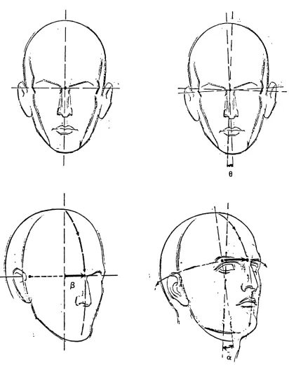
The head of the human being can be thought of as an ellipsoid that sits on the
top of the torso, and is attached to it from the center by the neck. Hence, the head
movement can be viewed as rotations o , ~ , and
e
about z , y, and z axes, respec-tively, which pass through the center of the ellipsoid (see Fig. 3). Viewed from mostangles, the head looks like an ellipse. The elongation and orientation of this ellipse are
related to the head rotation angles o , ~ and 8. For example, the length of the minor axis is about two thirds that of the major axis in the normal front view position [8,9].
This ratio changes as the head moves up or down, and hence, it is related to the value
of the angle n (assuming the x-y plane is the image plane). The angle
e
is directlythe symmetry of the head view in the original image.
Only the eyes, nose, and mouth are significant to the new coding methodology,
The local orientation of these primitives is related to the global orientation of the
head. In fact, the shapes of these features are highly dependent on the rotation angle
~. Ifthe head is rotated to the left side, then the left eye and ear do not appear in the
image, and the mouth, nose and right eye have side views. In the frontal view of the
head (the normal case) the angle
f3
is zero, and the effect of angle a is not thatsignificant; hence it can be ignored.
4.2. Extracting The Facial Features
The location of the three most important features: eyes, nose and mouth can
easily be determined. It is well known in the art of drawing the human head that the
head is approximatelly five eye-lengths wide [8,9] (see Fig. 4). Both eyes lie on the
midway line, and the distance between them is equal to almost one eye-length. The
nose starts at the center of the face and descends to a point mid-way between the
bridge of the nose and the base of the chin. The width of the nose at its base is also
equal to one eye-length. The mouth barrel starts at the nose and extends two thirds of
the distance down from the nose to the chin. The sides of the barrel align with the
centers of the eye sockets. These measurements are used to locate the head features
The global orientation of the head is determined from the head view in the
image. This view has an elliptic shape under the ellipsoid model of the head. The
parameters of the ellipse are estimated from the points on the edge of the head by
fitting an ellipse through these points. A simple way to do this is by first extracting
the contour of the head and then minimizing the fitting error. The quadratic form for
an ellipse is given by,
!(x,y;a,b,c,d,e)
=
ax2+
2bxy+
cy2+
dx+
ey - 1 = 0 and the fitting error is defined byn
S = ~ (LlXi)2+(LlYi)2
i=1
(2)
(3)
where ~xi and ~Yi are the x and y deviations of the point (xi,Yi) from the ellipse
con-tour.
Let (cz,cy ) be the center of the ellipse that fits the head contour, and let lz' ly
and
e
denote the minor and major semi-axes and orientation of the ellipse, respec-tively. Using the previously described model of the head, the location of the eyes,nose, and mouth are given below in terms of (cx,c y), 8, lx' and lye
Eyes:
If the length of each eye is e/ and the centers of right and left eyes are (crez,crey )
and (clez 'cley ), respectively, then,
(4b)
(4c)
Nose:
If the center, length, and base width of the nose are denoted by (nc%,ncy ) , nh
and nw , respectively, then,
1
nc%
=
c -% L sin84
1
nCll
=
c y+
Lcose4
nh
=
!JL
2
2/x
nw
=
-5
(5a)
(5b)
(5c)
Mouth:
If the center, height, and width of the mouth barrel are denoted by (mcz,mcy ),
mh and mw , respectively, then,
21
(6a)
mc% = c% -
.:s.
sine3
21
=!JL
3
mw
=
4.3. Database and Primitives Matching
(6b)
(6c)
The best match from the database is found by comparing the extracted feature
with features of the same type from the database. The database for this class of
images is very simple. The entries of the database are grouped under the feature
types; hence there are groups labeled eyes, nose, and mouth. Each group (e.g. the
eyes) contains various states that may be assumed by its corresponding feature (e.g.
eye is closed, slightly opened, or fully opened). Since each feature in the original
image is extracted by its name, a feature is matched to only one group.
Mean-square-error is used as a measure of matching Mean-square-error. Since there may be slight
miss-alignment between the extracted feature and those in the database, it is necessary to
displace the feature one or two pixels in each direction and compare it with those in
the database. The feature with the least mean-square-error is taken as the best
match.
The parameters of the ellipse, normalization factors of the primitives, and the
order of the feature's best match are sent to the receiver, where the same database is
used to reconstruct a faithful image replica. The decoding process starts by rotating
the head in the previous frame by the appropriate angle, then updating the facial
4.4. Implementation and Simulation Results
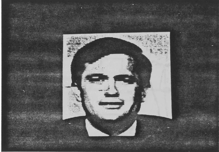
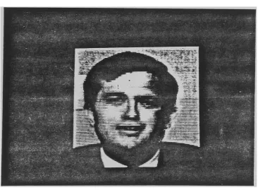
The described Primitive-Based image coding technique was successfully imple-mented. The coder was simulated using head and shoulder images of the type shown in Fig. 5 and 6. The size of these images is 128X128 pixels, and each pixel is represented by 8 bits. The previous frame shown in Fig. 5 was assumed to be known to the receiver before coding the image of Fig. 6.
To locate the eyes, nose and mouth, a Sobel edge detector
[10]
was used to find the edges in the image. These edges were thinned using the Chen et. al. thinning algo-rithm [11], and the ellipse which fit the head contours was estimated from the thinned contours. Finally, the three features (eyes, nose, and mouth) were extracted using the ellipse parameters and equations(4)-(6).
The extracted features were matched to a simple database that was created using the same image sequence. The head of the previous frame was rotated, and the three primitives were projected. The transition regions around the head and primitives were smoothed using an average filter. Thedecoded image is shown in Fig. 7.
However, with the availability of cheap memory devices, memory requirement is not a limitation of the new technique.
5. Conclusion
6. References
[1] N. Magnenat-Thalmann and D. Thalmann, Computer Animation, Springer-Verlag, Tokyo 1985.
[2] G. Davies, H. Ellis, and J. Shepherd, Perceiving and Remembering Faces,
Academic Press, London 1981.
[3] M.L. Gillenson and B. Chandrasekaran, tIA Heuristic Strategy for Developing
Human Facial Images on a CRT," Pattern Recognition, vol. 7, pp. 187-196, 1975.
[4]
N. Burtnyk and M. Wein, "Computer-Generated Key-Frame Animation," J.0/
Society0/
Motion Picture and Television Engineers, vol. 80, pp. 149-153, 1971.[5]
A.N. Netravali and J.O. Limb, "Picture Coding:A
review," Proc. IEEE, vol. 68,pp. 366-406, March 1980.
[6]
M.
Kunt, A. Konomopoulos andM.
Kocher, "Second-Generation Image Cod-ing," Proc. IEEE, vol. 73, pp. 549-574, April 1985.[7]
S.A. Rajala,M.R.
Civanlar and W.M. Lee,"A
Second Generation Image Coding Technique Using Human Visual System Based Segmentation," Proc. ICASSP'87,pp. 1362-1365, April 1987 .,
[8]
B.
Hogarth, Drawing the Human Head, London 1975.[9] S. SimmonsIII and M.S. Winer, The Creative Process, Prentice-Hall, New Jersey 1977.
[10]
E.L. Hall, Computer Image Processing and Recognition, Academic Press, New York 1979.PRIMITIVE
...---
PRIMITIVE~
...
--.
...
MATCHER v-um
CONTROLLE~ - - - -...-.
DATABASE
UPDATOA ...---... DATABASE
...-._---~
FIGURE
1:
PRIMITIVE-BASED IMAGE CODER
FRAME
B..FFER
BINARY
SEO..ENCE
BINARY CXXl:R
BINARY SEQJB\CE
BINARY DEca::ER
OUTPUT IMAGE
DATABASE~ ~DATABASE
~__. . UPDATOA
Fig.
4.
Head Features Location FromFront View,
Fig. 5 128x 128 Previous Frame
. .
. . . ' . . .
-: • r~ , _ - ....
v .. __ . " • • ._ • •
Fig. 6
128X128Input Image To Be Coded
Fig. 7
128x
128Decoded Output
Image
. . .
- .