ISSN(Online) : 2319-8753 ISSN (Print) : 2347-6710
I
nternational
J
ournal of
I
nnovative
R
esearch in
S
cience,
E
ngineering and
T
echnology
(An ISO 3297: 2007 Certified Organization)
Vol. 5, Issue 3, March 2016
A Novel Approach on Reactive Current
Reference Algorithm for the Facts Based
Multilevel Inverters
Balaji S1, Priyama Kasuna A2, Ganesh V.N3
Asst. Prof, Dept of EEE, SRM University, Chennai, India1
PG Scholar, Dept of EEE, SRM University, Chennai, India2
Asst. Prof, Dept of EEE, SRM University, Chennai, India3
ABSTRACT: In this paper, a power line conditioner using a cascade multilevel inverter is presented for voltage regulation, reactive power (var) compensation, and harmonic filtering. The cascade M-level inverter consists of (M 1)=2 H bridges, in which each bridge has its own separate dc source. This new inverter can: 1) generate almost sinusoidal waveform voltage with only one time switching per line cycle; 2) eliminate transformers of multipulse inverters used in the conventional static var compensators; and 3) make possible direct connection to the 13.8-kV power distribution system in parallel and series without any transformer. In other words, the power line conditioner is much more efficient and more suitable to var compensation and harmonic filtering of distribution systems than traditional multipulse and pulsewidth modulation inverters. It has been shown that the new inverter is especially suited for var compensation. This paper focuses on feasibility and control schemes of the cascade inverter for voltage regulation and harmonic filtering in distribution systems. Analytical, simulated, and experimental results show the superiority of the new power line conditioner. Index Terms—Active power filter, multilevel inverter, power line conditioner.
I. INTRODUCTION
ISSN(Online) : 2319-8753 ISSN (Print) : 2347-6710
I
nternational
J
ournal of
I
nnovative
R
esearch in
S
cience,
E
ngineering and
T
echnology
(An ISO 3297: 2007 Certified Organization)
Vol. 5, Issue 3, March 2016
using an 11-level cascade inverter (21-level line-to-line voltage waveform) has been built. Analytical, simulated, and experimental results show the feasibility and superiority of the proposed power line conditioner.
II. PRINCIPLES OF OPERATION
The STATCOM provides reactive power compensation and voltage regulation by acting as a controlled current source connected in parallel with the system bus. The controlled current source in the proposed system is realized using a current-controlled CMC. A typical configuration of a CMC based STATCOM The system consists of three bus grid which bus B2 is considered as source point for STATCOM. The CMC based STATCOM is connected through bus B2 with coupling transformer and harmonics elimination filter three types of loads are connected through transformer in bus B3 for load variation purpose. The load and STATCOM currents are directed in the three bus system.
III. CIRCUIT DESCRIPTION
Two important circuits are mainly discussed in STATCOM. They are, 1. Power Circuit 2. Control Circuit 3.1 .Power circuit The power circuit configuration is nothing but connection of a cascaded multilevel converter in the system. In reactive power compensation, seven level cascaded-multilevel converter with separated DC capacitors are constructed with a number of identical three H-bridge converters. The cascaded converter method is very simple and less components. The CMC based STATCOM improves the dynamic responses of the power system network. The control circuit is capable of independently controlling the direct axis component itd and the quadrature axis component itq of the VSC/CMC current with minimal coupling between them. The controllers generate the desired values of dq components of the VSC/CMC terminals. The PWM pattern generator uses these signals to generate the gating pulses for converter Control scheme has some units as follows,
1. Step input control 2. RMS voltage control 3. Power factor control 4. DC voltage control 5. Cascaded control
The Three-Phase V-I Measurement unit is used to measure the voltages and currents in a circuit. It can be measured the voltages and currents in per unit (p.u.).The per unit values of main system bus are given to abc to dqo converter. RMS value is taken from system bus and ilq value is known from load current for power factor reference value.
ISSN(Online) : 2319-8753 ISSN (Print) : 2347-6710
I
nternational
J
ournal of
I
nnovative
R
esearch in
S
cience,
E
ngineering and
T
echnology
(An ISO 3297: 2007 Certified Organization)
Vol. 5, Issue 3, March 2016
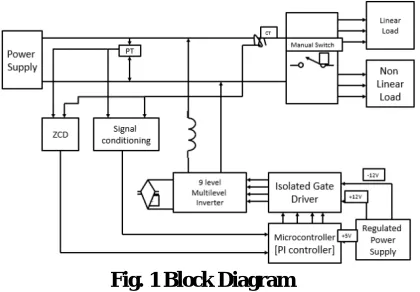
Fig. 1 Block Diagram
Cascaded controller based STATCOM is designed for seven level cascaded multilevel converter (CMC)[11]-[15]. This proposed controller reduced the THD values [16]. This result is given clearly in fig.14. THD value of voltage is 16.24% and current is 0.76% as shown in fig.15. THD values are minimized in the converter output voltage and current. Active and reactive power of source are shown in fig.16 and compensation is identified through reactive power variation. Power factor is improved as three phase supply output.
IV. POWER SYSTEM NETWORK
The Power system network considered is a 33kV network with a long transmission line. The 33kV is stepped down to 415V via a power transformer and feds a 1.5MW non-linear load. The STATCOM is connected at the point of common coupling near the load. The coupling transformer of the STATCOM is rated at 5500V/33kV, 6MVA. The STATCOM is connected at the primary side of the coupling transformer.
Though the modern STATCOM configuration studies suggests the method of having a transformerless STATCOM for HV applications, in order to remove the burden of transformer cost, it has its own drawbacks, i.e., the switches required in such transformerless configurations are HV Switches which are difficult to control and the operating and replacement costs are high, moreover they require separate filter units in order to filter their harmonics. Hence the advantages of having a coupling transformer is that it itself acts as a harmonic filter, moreover the switches can also be operated at low voltages hence reduced cost and complexity.
V.STATCOM CONTROLLER
The Control circuit topology for the multilevel inverter (MLI-1 and MLI-2) voltage source Vdc. The STATCOM Voltage Magnitude controller compares the grid voltage magnitude with a reference voltage magnitude and generates the difference as an error signal. This error signal is amplified by a gain and is given as control input to the STATCOM inverter controlled DC voltage source.
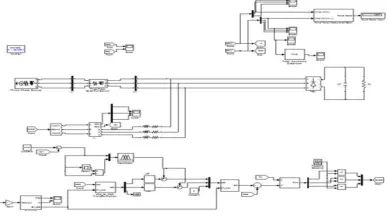
The system configuration shown in Fig. 1 is considered for simulation. The simulation study is carried out using MATLAB/ SIMULINK. The system parameters are given in Table I. The following are the scenarios subjected to the simulation:
The Source voltage is initially set at 1pu at 33kV base.
Sag of 15% (i.e., 0.85pu) is created in the load voltage from the time 0.1 to 0.2secs
A Swell of 10% (i.e., 1.1pu) is created in the load voltage from the time 0.2 to 0.3secs.
ISSN(Online) : 2319-8753 ISSN (Print) : 2347-6710
I
nternational
J
ournal of
I
nnovative
R
esearch in
S
cience,
E
ngineering and
T
echnology
(An ISO 3297: 2007 Certified Organization)
Vol. 5, Issue 3, March 2016
The load voltage is reset to 1pu at the time of 0.4secs and the simulation is stopped at 0.5secs. The load voltage waveform is observed for variations, as the expected result shall be a uniform load voltage waveform of 1pu without any abrupt fluctuations in the load voltage waveform as indicated in the source voltage scenarios.
Dynamic representation for load variation. The Load current and dq axis current variation is clearly shown through Fig.10 Due to fast stable operation of STATCOM, dq currents of source terminal get effective responses as shown in Fig.11. As shown in fig.8,the system reactance, Xeq, is a part of the feedback loop and it is crucial to note that Xeq varies as loads are added or rejected from the power system . Therefore the overall closed loop gain and the stability margin of the STATCOM are affected by Xeq. If the impedance of the power system increases (weak system) , the amount of voltage is varied. The STATCOM reactive current is also varied and the overall system tends to instability. If the power system impedance decreases (strongsystem), the system is stable, although the response is slower than that of the weak system.
Fig. 2 Simulink Diagram
VI. CASCADED CONTROLLER.
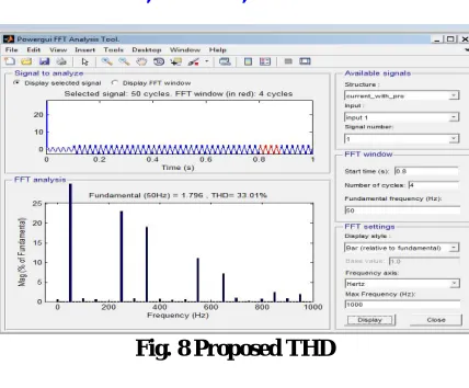
Cascaded controller based STATCOM is designed for seven level cascaded multilevel converter (CMC)[11]-[15]. This proposed controller reduced the THD values [16]. This result is given clearly in fig.14. THD value of voltage is 16.24% and current is 0.76% as shown in fig.15. THD values are minimized in the converter output voltage and current. Active and reactive power of source are shown in fig.16 and compensation is identified through reactive power variation. Power factor is improved. Three phase supply output.
VII.RESULTS AND DISCUSSION SIMULATION OUTPUT
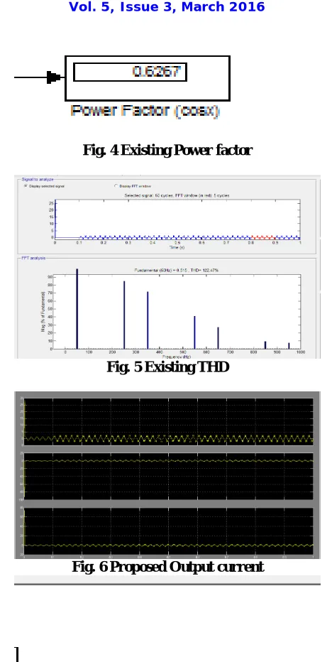
The STATCOM is connected to the bus B2 for 230KV, 50Hz through 20/230KV, 100MVA coupling transformer as shown in fig.1. On this power system network, the +/-100 MVAR STATCOM can compensate reactive power and maintain effective voltage profile. The reactive power generation or absorption by generating converter voltage which is in phase with the source voltage in bus B2 [11].When the CMC output voltage is lower than the source voltage , the STATCOM will absorb reactive power, when capacitor voltage is higher, it will generate the reactive power and supply the reactive power to bus B2.
ISSN(Online) : 2319-8753 ISSN (Print) : 2347-6710
I
nternational
J
ournal of
I
nnovative
R
esearch in
S
cience,
E
ngineering and
T
echnology
(An ISO 3297: 2007 Certified Organization)
Vol. 5, Issue 3, March 2016
Fig. 4 Existing Power factor
Fig. 5 Existing THD
Fig. 6 Proposed Output current
ISSN(Online) : 2319-8753 ISSN (Print) : 2347-6710
I
nternational
J
ournal of
I
nnovative
R
esearch in
S
cience,
E
ngineering and
T
echnology
(An ISO 3297: 2007 Certified Organization)
Vol. 5, Issue 3, March 2016
Fig. 8 Proposed THD
VIII. CONCLUSION
This Paper presents a comparative study on the MATLAB SIMULINK simulation results high power STATCOM which employs Voltage magnitude control for both Cascaded Multilevel Inverter and Multistring Multilevel Inverter. It is found from the above simulation result observations that the Improved Multistring Multilevel Inverter is best suitable configuration for High Power STATCOM Applications. Moreover the number of switches used is less when compared with Cascaded Multilevel inverter, hence the cost is also less and the switching losses are also low. The MATLAB/SIMULINK based simulation results confirm the feasibility and effectiveness of the proposed approach to regulate the load voltage using the improved Multi-String inverter based STATCOM.
REFERENCES
[1] Law Kah Haw, Mohamed S.A.Dahidah, HaiderA.F.Almurib, “SHE-PWM Cascaded Multilevel Inverter with adjustable DC voltage levels control for STATCOM Applications” IEEE International Journal of Scientific Research in Science, Engineering and Technology (ijsrset.com) 167 Publications, VOL. 29, NO. 12, 2014. –describes about the study on Tranformerless STATCOM and its issues.
[2] N.N.V.SurendraBabu and B.G .Fernandes, “Cascaded TwoLevel Inverter-Based Multilevel STATCOM for High-Power Applications” IEEE Publications, Feb. 2014.
[3] B. Singh, R. Saha, A. Chandra, and K. Al-Haddad, “Static synchronous compensators (STATCOM): A review,” IET Power Electron., vol. 2, no. 4, pp. 297–324, 2009.
[4] H. Akagi, H. Fujita, S. Yonetani, and Y. Kondo, “A 6.6-kV transformerless STATCOM based on a five-level diodeclamped PWM converter: System design and experimentation of a 200-V 10-kVA laboratory model,” IEEE Trans. Ind. Appl., vol. 44, no. 2, pp. 672–680, Mar./Apr. 2008. [5] A. Shukla, A. Ghosh, and A. Joshi, “Hysteresis current control operation of flying capacitor multilevel inverter and its application in shunt compensation of distribution systems,” IEEE Trans. Power Del., vol. 22, no. 1, pp. 396–405, Jan. 2007.
[6] H. Akagi, S. Inoue, and T. Yoshii, “Control and performance of a transformerless cascaded PWM STATCOM with star configuration,” IEEE Trans. Ind. Appl., vol. 43, no. 4, pp. 1041– 1049, Jul./Aug. 2007.
[7] Y. Liu, A. Q. Huang, W. Song, S. Bhattacharya, and G. Tan, “Small-signal model-based control strategy for balancing individual dc capacitor voltages in cascade multilevel inverterbased STATCOM,” IEEE Trans. Ind. Electron., vol. 56, no. 6, pp. 2259–2269, Jun. 2009.
[8] H. P. Mohammadi and M. T. Bina, “A transformerless mediumvoltage STATCOM topology based on extended modular multilevel converters,” IEEE Trans. Power Electron., vol. 26, no. 5, pp. 1534–1545, May 2011.
[9] X. Kou, K. A. Corzine, and M. W. Wielebski, “Overdistention operation of cascaded multilevel inverters,” IEEE Trans. Ind. Appl., vol. 42, no. 3, pp. 817–824, May/Jun. 2006.
[10] K. K. Mohaptra, K. Gopakumar, and V. T. Somasekhar, “A harmonic elimination and suppression scheme for an open-end winding induction motor drive,” IEEE Trans. Ind. Electron., vol. 50, no. 6, pp. 1187–1198, Dec. 2003.
[11] Y. Kawabata, N. Yahata, M. Horii, E. Egiogu, and T. Kawabata, “SVG using open winding transformer and two inverters,” in Proc., 35th An-nual IEEE Power Electron. Specialists Conf., 2004, pp. 3039–3044.
[12] S. Ponnaluri, J. K. Steinke, P. Steimer, S. Reichert, and B. Buchmann, “Design comparison and control of medum voltage STATCOM with novel twin converter topology,” in Proc., 35th Annu. IEEE Power Electron. Specialists Conf., 2004, pp. 2546– 2550.
[13] N. N. V. SurendraBabu, D. Apparao, and B. G. Fernandes, “Asymmetrical dc link voltage balance of a cascaded two level inverter based STATCOM,” in Proc., IEEE TENCON, 2010, pp. 483–488.
[14] IEEE Criteria for Class IE Electric Systems, IEEE Standard 141-1993.
[15] C. Schauder and H. Mehta, “Vector analysis and control of advanced static VAR compensators,” in Proc. Inst. Elect. Eng. C., Jul. 1993, vol. 140, no. 4, pp. 299–305.
ISSN(Online) : 2319-8753 ISSN (Print) : 2347-6710
I
nternational
J
ournal of
I
nnovative
R
esearch in
S
cience,
E
ngineering and
T
echnology
(An ISO 3297: 2007 Certified Organization)
Vol. 5, Issue 3, March 2016
[18] B. Blazic and I. Papic, “Improved D-statcom control for operation with unbalanced currents and voltages,” IEEE Trans. Power Del., vol. 21, no. 1, pp. 225–233, Jan. 2006.
[19] A. Leon, J. M. Mauricio, J. A. Solsona, and A. GomezExposito, “Soft-ware sensor-based STATCOM control under unbalanced conditions,” IEEE Trans. Power Del., vol. 24, no. 3, pp. 1623–1632, Jul. 2009.