Analysis of Optimal Utilization of Series Inverter Sizing of Upqc and
Maximum Utilization of Power-Electronic Converters
1. THASLEEM BEGUM, 2. M.CHANDRA SHEKAR
1.PG SCHOLAR,DEPARTMENT OF EEE, ANNAMACHARYA INST.OF TECH & SCIENCES
2.ASST PROFESSOR,(PURSUING PHD IN VELTECH DR.RR&DR.SR UNIVERSITY), DEPARTMENT OF EEE, ANNAMACHARYA INST.OF TECH & SCIENCES
ABSTRACT: The analysis and optimal utilization of series inverter unified power quality conditioner (UPQC) for simultaneous voltage sag/swell and load reactive power compensation are presented in this paper. The main objective of the series inverter of UPQC is to perform simultaneous 1) voltage sag/swell compensation and 2) load reactive power sharing with the shunt inverter. The active power control approach is used to compensate voltage sag/swell and is integrated with the theory of power angle control (PAC) of UPQC to coordinate the load reactive power between the two inverters. Since the active and reactive powers simultaneously delivered by series inverter, this concept is named as UPQC-S (S stands for complex power). MATLAB/SIMULINK model and its results are presented to analyze the developed concept.
Keywords: Active power filter; power angle control; power quality; reactive power compensation; unified power quality conditioner; voltage sag and swell compensation
1.INTRODUCTION
The different power quality problem makes
extremely vulnerable the modern power
distribution system. The current and voltage
harmonics issues are increase due to the extensive
use of nonlinear loads. Furthermore, the
penetration level of renewable energy systems
based on solar energy, wind energy, fuel cell, etc.,
installed at distribution as well as transmission
levels is increasing significantly [1]. This
integration of renewable energy sources in a power
system is further imposing new challenges on the
electrical power industry to accommodate these
newly emerging distributed generation systems [2].
To maintain the controlled power quality policy,
some kind of reimbursement at all the power levels
is becoming a common practice [3]. At the
distribution level, UPQC is a most attractive
solution to compensate several most important
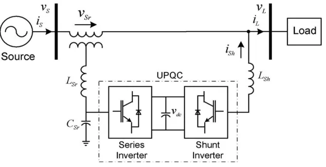
power quality problems [4]. The general block
diagram representation of a UPQC-based system is
shown in Fig. 1. It essentially consists of two
voltage source inverters connected back to back
using a common dc bus capacitor. This paper deals
with a novel concept of optimal utilization of a
International Journal of Research
Available at https://edupediapublications.org/journals
e-ISSN: 2348-6848 p-ISSN: 2348-795X Volume 04 Issue 14 November 2017
Fig. 1 Unified power quality conditioner (UPQC) system configuration.
The voltage sag/swell on the system is one of the
most significant power quality problems [5]. The
voltage sag/swell can be effectively remunerated
using a dynamic voltage restorer, series active
filter, UPQC, etc.. Among the available power
quality enhancement devices, the UPQC has
better sag/swell compensation capability [6].
Three significant control approach for UPQC can
be found to control the sag on the system: 1)
Active power control approach in which an
in-phase voltage is injected through a series
Inverter, popularly known as UPQC-P.
Reactive power control approach in which a
quadrature voltage is injected, known as UPQC-Q.
A minimum VA loading approach in which a
series voltage is injected at a certain angle, in this
paper called as UPQC-VAmin. Among the
aforementioned three approaches, the quadrature
voltage injection requires a maximum series
injection voltage, whereas the in-phase voltage
injection requires the minimum voltage injection
enormity. In a minimum VA loading come
within reach of, the series inverter voltage is
injected at an optimal angle with respect to the
source current [7]. Besides the series inverter
injection, the current drawn by the shunt inverter,
to maintain the DC link voltage and the overall
power balance in the network, plays an important
role in influential the overall UPQC VA loading.
The key contributions of this paper are outlined as
follows:
A. The series inverter of UPQC-S is utilized for
simultaneous voltage sag/swell compensation
and load reactive power compensation in
coordination with shunt inverter.
B. The available active power, VA loading is
utilized to its utmost capacity during all the
working situation contrary to UPQC- VAmin.
C. The proposed UPQC-S conception scenario
covers voltage sag and swell conditions
effectively.
UPQC-S is carried out. The achievability and
usefulness of the proposed UPQC-S approach are
validated by simulation results.
II.UNIFIED POWER FLOW CONTROLLER
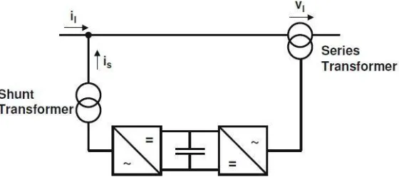
The UPFC is a combination of a static compensator and static series compensation. It acts as a shunt
compensating and a phase shifting device simultaneously.
Fig. 2 Principle configuration of an UPFC
The UPFC consists of a shunt and a series
transformer, which are associated via two voltage
source converters with a common DC- capacitor
[8]. The DC circuit allows the active power
replace between shunt and series transformer to
control the phase shift of the series voltage. [9]
This setup, as shown in Fig.2, provides the full
controllability for voltage and power flow. The
series converter needs to be protected with a
Thyristor bridge [10]. Due to the high efforts for
the Voltage Source Converters and the protection,
an UPFC is getting quite expensive, which
restrictions the practical applications where the
voltage and power flow control is required
simultaneously.
III.OPERATING PRINCIPLE OF UPFC
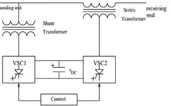
The basic components of the UPFC are two
voltage source inverters (VSIs) sharing a
common dc storage capacitor, and connected to
the power system through coupling transformers
[11]. One VSI is connected to in shunt to the
transmission system via a shunt transformer,
while the other one is connected in series through
a series transformer. The Fig. 3 shows the
schematic diagram of basic UPFC functional
International Journal of Research
Available at https://edupediapublications.org/journals
e-ISSN: 2348-6848 p-ISSN: 2348-795X Volume 04 Issue 14 November 2017
Fig. 3 Functional scheme of UPFC
The series inverter is controlled to inject a
symmetrical three-phase voltage system (Vse), of
controllable magnitude and phase angle in series
with the line to control active and reactive power
flows on the transmission line. So, this inverter
will exchange active and reactive power with the
line. The reactive power is electronically
provided by the series inverter, and the active
power is transmitted to the dc terminals. The
shunt inverter is operated in such a way as to
demand this dc terminal power (positive or
negative) from the line keeping the voltage across
the storage capacitor Vdc constant [12]. So, the
net real power absorbed from the line by the
UPFC is equal only to the losses of the inverters
and their transformers.
The outstanding capacity of the shunt inverter can
be used to exchange reactive power with the line
so to provide a voltage regulation at the
connection point.
The two VSI’s can work independently of each
other by separating the dc side. So in that case,
the shunt inverter is operating as an STATCOM
that generates or absorbs reactive power to
regulate the voltage magnitude at the connection
point. Instead, the series inverter is operating as
SSSC that generates or absorbs reactive power to
regulate the current flow, and hence the power
low on the transmission line.
A. Shunt Inverter
The UPFC has many possible operating modes.
In particular, the shunt inverter is operating in
such a way to inject a controllable current, ish
into the transmission line. The shunt inverter can
be controlled in two different modes:
1) VAR Control Mode: The orientation input is
an inductive or capacitive VAR request. The
shunt inverter control translates the
VAR reference into a corresponding shunt
current request and adjusts gating of the
this mode of control a feedback signal
representing the dc bus voltage, Vdc, is also
required.
2) Automatic Voltage Control Mode: The shunt
inverter reactive current is without human
intervention regulated to maintain the
transmission line voltage at the point of
connection to a reference value. For this
mode of control, voltage feedback signals are
obtained from the sending end bus feeding the
shunt coupling transformer.
B. Series Inverter
The series inverter controls the magnitude and
angle of the voltage injected in series with the
line to influence the power flow on the line. The
actual value of the injected voltage can be
obtained in several ways.
1) Direct Voltage Injection Mode: The reference
inputs are directly the enormity and phase
angle of the series voltage.
2) Phase Angle Shifter Emulation Mode: The
orientation input is phase displacement
between the sending end voltage and the
receiving end voltage. Line Impedance
Emulation mode: The reference input is an
impedance value to insert in series with the
line impedance
Automatic Power Flow Control Mode: The
reference inputs are values of P and Q to maintain
on the transmission line regardless of system
changes
IV.SIMULATION RESULTS AND
DISCUSSION
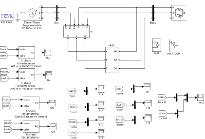
The performance of the proposed concept of
simultaneous load reactive power and voltage
sag/swell compensation has been evaluated by
simulation as shown in Fig. 4. To analyze the
performance of UPQC-S, the source is assumed to
be purely sinusoidal. Furthermore, for better
visualization of results, the load is considered as
highly inductive. The supply voltage which is
available at UPQC terminal is considered as three
phase, 60 Hz, 600 V (line to line) with the
maximum load power demand of 15 kW + j
15kVAR (load power factor angle of 0.707 lag.).
The performances of the proposed UPQC-S
International Journal of Research
Available at https://edupediapublications.org/journals
e-ISSN: 2348-6848 p-ISSN: 2348-795X Volume 04 Issue 14 November 2017
Fig. 4 proposed MATLAB/Simulink Model
(b)
Load voltage, VL.
International Journal of Research
Available at https://edupediapublications.org/journals
e-ISSN: 2348-6848 p-ISSN: 2348-795X Volume 04 Issue 14 November 2017
(d)
DC
(e)
Power angle δ relation between supply and load voltages.
(f)
Supply current, IS.
International Journal of Research
Available at https://edupediapublications.org/journals
e-ISSN: 2348-6848 p-ISSN: 2348-795X Volume 04 Issue 14 November 2017
(h)
Injected Shunt inverter current.
(j) Power angle δ during voltage swell condition.
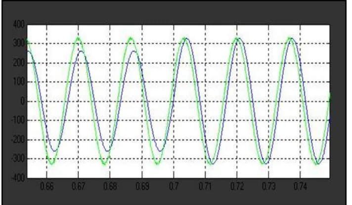
Fig. 5 (a-j) Performance of the UPQC-S under voltage sag and swell
conditions
CONCLUSION
In this paper, a new concept of controlling complex power (simultaneous active and reactive powers) through a series inverter of UPQC is introduced and named as UPQC-S. The proposed UPQC-S concept is analyzed for voltage sag and swells conditions and formulated mathematically. The developed comprehensive equations for UPQC-S can be utilized to estimate the required series injection voltage and the shunt compensating current profiles (magnitude and phase angle), and the overall VA loading both under voltage sag and swell conditions. The effectiveness of the proposed UPQC-S under simultaneous voltage sag/swell conditions and load reactive power sharing feature are demonstrated in simulation result. The significant advantages of UPQC-S over general UPQC applications are: 1) the multifunction ability of
power; 2) better utilization of series inverter rating of UPQC; and 3) reduction in the shunt inverter rating due to the reactive power sharing by both the inverters.
REFERENCES
[1] S. V. Sivanagaraju , K. Kumar , K. Rajasekharachari, “Performance Comparison Of Variable Speed Induction Machine Wind Generation System With And Without Fuzzy Logic Controller”, International Journal of Innovative Research and Development, vol. 2.7,2013.
International Journal of Research
Available at https://edupediapublications.org/journals
e-ISSN: 2348-6848 p-ISSN: 2348-795X Volume 04 Issue 14 November 2017
Available online: https://edupediapublications.org/journals/index.php/IJR/ P a g e | 1865
[3] Rajasekharachari, K., G. Balasundaram, and K. Kumar. "Implementation of A Battery Storage System of An Individual Active Power Control Based on A Cascaded Multilevel Pwm Converter." International Journal of Innovatiive Research in Science, Engineering and Technology, vol. 2.7, 2013.
[4] Mani, P. K., and Dr K. Siddappa Naidu. "Unified Power Quality Conditioner (UPQC) with Hysteresis Controller for Power Quality Improvement in Distribution System." International Journal of Applied Engineering Research, vol. 10.9 , pp.9124-9130, 2015.
[5] Ganguly, Sanjib. "Multi-objective planning for reactive power compensation of radial distribution networks with unified power quality conditioner allocation using particle swarm optimization." IEEE Transactions on Power Systems, vol. 29.4, pp. 1801-1810, 2014
[6] Panda, Anup Kumar, and Nishant Patnaik. "Management of reactive power sharing & power quality improvement with SRF-PAC based UPQC under unbalanced source voltage condition." International Journal of Electrical Power & Energy Systems, vol. 84, pp. 182-194, 2017.
[7] Ambati, Bharath Babu, and Vinod Khadkikar. "Optimal sizing of UPQC considering VA loading and maximum utilization of power-electronic converters." IEEE transactions on power delivery, vol. 29.3, pp. 1490-1498, 2014.
[8] Ansari, Abdul Quaiyum, Bhim Singh, and Mashhood Hasan. "Algorithm for power angle control to improve power quality in
distribution system using unified power quality conditioner." IET Generation, Transmission & Distribution, vol. 9.12, pp. 1439-1447, 2015.
[9] Rajasekharachari, K., and K. Shalini. "Kumar. K and SR Divya, “Advanced Five Level-Five Phase Cascaded Multilevel Inverter with SVPWM Algorithm”." International Journal of Electrical Engineering & Technology (IJEET), vol. 4.4, pp.144-158, 2013.
[10] Ye, Jian, and Hoay Beng Gooi. "Optimization of the Size of UPQC System Based on Data-Driven Control Design." IEEE Transactions on Smart Grid, 2016. [11] Ganguly, Sanjib. "Impact of unified power-quality conditioner allocation on line loading, losses, and voltage stability of radial distribution systems." IEEE
Transactions on Power Delivery, vol. 29.4, pp. 1859-1867, 2014.