Available online: https://edupediapublications.org/journals/index.php/IJR/ P a g e | 741
Minimization Of Inter Carrier Interference Using Iterative
Technique for Mimo-Ofdm
A Swathi & Dr. S.V.R.K. Rao
(M.Tech) Department of ECE (DECS) GIER, Rajahmundry Professor & HOD Department of ECE GIER, Rajahmundry
Abstract
–
In orthogonal frequency divisionmultiplexing – multiple input multiple output (OFDM-MIMO) systems, in multipath fading channels the time period of an OFDM block is not constant. As a result, the sub-carriers lose their orthogonality and create intercarrier interference (ICI). Lot of research has been carried out to cancel or mitigate the effects of ICI in OFDM-MIMO systems but these methods are computationally complex. Here we use a low-complexity based frequency-domain algorithm to cancel the ICI created in time-varying multipath channels. Simulation with BPSK and QPSK demonstrates the performance of our algorithm in comparison to channels with ICI and no ICI. The results are also compared with zero forcing equalization algorithm which is the algorithm used presently in the OFDM-MIMO systems. Based on Fast Fourier Transform, iterative linear MSE has been implemented to maximize the output signal to noise/interference ratio in the MMSE estimates during iterative detection. It shows that 15 db signal to noise gain is achieved when bit error rate is𝟏𝟎−𝟗.
Keywords
:
Time-varying multipath channels, Inter carrier interference (ICI), minimum mean square error, multiple- input multiple- output .I. Introduction
In multipath fading channel, the received signal undergoes frequency-selective fading. If the symbol period is not too large as compared to the delay spread of the channel, the current symbol will affect the subsequent symbol as well. This process is known as inter-symbol interference (ISI). For a single-carrier system, as the data rate increases the ISI will also rise significantly. To avoid this problem multiple carriers are used for high rate data transmission. Multi-carrier systems can be regarded as a type of orthogonal frequency division
Multiple access (OFDMA) method as they transmit different symbols with orthogonal sub-channels in parallel form. The computationally efficient fast Fourier transform (FFT) is used to transmit data parallely over a large number of orthogonal subcarriers. OFDM-MIMO systems are being used in the latest generation of wireless mobile communications for achieving high-speed data transmission and efficiency. The subcarrier signals are overlapped in spectrum. As long as there is
orthogonality between the sub-channels, there is no ICI thereby creating distortion less transmission channel. [1]
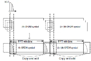
A guard interval is used before each transmitted data block to eliminate ISI. ICI may also occur if the length of the guard interval is shorter than the spread delay of the multipath channel.[2] Such ICI can be easily eliminated by copying the guard interval part of the next OFDM symbol and adding it to the head part of the current OFDM symbol as shown in figure 1.
Fig 1 Copying and adding the guard interval of the next symbol into the head part of the current symbol to
prevent ICI [3]
There are basically two types of noise created by the carrier signal – the phase noise and the carrier frequency offset (CFO). The CFO is caused by Doppler frequency shift in the multipath channel. The subcarrier frequency component is affected by other subcarrier frequency components and this also leads to ICI. Actually the CFO can be divided into two parts integer CFO (IFO) and fractional CFO (FFO). The IFO does not disturbs the orthogonality of the subcarriers and hence no ICI is created but in case of FFO, the orthogonality among the subcarriers is disturbed which leads to ICI. [4]
Available online: https://edupediapublications.org/journals/index.php/IJR/ P a g e | 742
channels. The problem becomes graver in case of multiple-input multiple-output systems because on each subcarrier of a specific receiver, the signals and ICI from all transmitters get missed up. [5]
To cancel the effects of ICI caused by this variation, different methods such as polynomial cancellation coding (PCC), self-cancellation scheme, time domain filtering, minimum mean-squared error (MMSE) etc. have been presented. Some of these approaches have good performance but are computationally expensive. Such methods can’t be used in high rate data transmissions. The other methods don’t demonstrate better performance. There are two major problems associated with ICI cancellation – estimation of the time variance in the channel by appropriate modeling and equalization. The model should be able to achieve balance between accuracy and complexity. The equalization implies that the receiver should be able to estimate the transmitted signal from the signal which is polluted by ICIs from various transmitters.
Multiple input multiple output technology is uses more number of antennas to make use of reflected signals to provide gains in channel throughput. MIMO is used in mainly new technologies these days to provide spectral efficiency combined with improved link reliability.[6]
The purpose of using MIMO-OFDM is it is the dominant air interface for 4G and 5G broad band wireless communications and it is the foundation for most advanced wireless networks . the main use of OFDM is Fast Fourier Transforms (FFT) may be used to simplify implementation and convert signals from time domain to frequency domain.
In this work, after analyzing the symbol energy distribution over sub-channels and the method of ICI generation, a frequency-domain partial MMSE method with lesser complexity is presented to mitigate the effects of ICI. This method is implemented in the receiver so that the subcarrier with the largest SINR than all the other undetected symbols is identified by using the MMSE detector on it and its neighbouring subcarriers.
The rest of the paper is detailed as follows: Section II gives the system model; section III explains the energy distribution over the symbols, section IV describes the proposed ICI cancellation scheme. The simulation results are presented in section V and section VI derives the conclusion.
II. System Model
In this section, we present the transmission model of MIMO-OFDM systems in linear time-varying channels over multipath fading channels. For MIMO-OFDM system, we have M number of transmitters and N
number of receivers. The OFDM symbol length is K. The l-th channel tap between the m-th transmitter and the n-th receiver at time slot t by 𝑙(,𝑡𝑚),𝑛′ l=0, 1… L-1, where L is the channel length. So for linear time-varying channel model in one frame, (𝑙,𝑡𝑚),𝑛 =𝑙,𝑚,𝑛+ 𝛿𝑡−𝑙𝛼𝑙,𝑚,𝑛, where 𝑙,𝑚,𝑛 =𝐾1 𝑙,𝑚,𝑛
(𝑡)
𝑙+𝐾−1
𝑡=𝑙 is the time
invariant part and 𝛼𝑙,𝑚,𝑛 is the time varying factor of its
l-th channel tap. 𝛿𝑖 = 𝑖 𝐾−
𝐾−1
2𝐾 Indicates the time-varying
step. For MIMO-OFDM, by regarding each pair of transmitter m and receiver n as a SISO-OFDM link, the time-domain signal received at the nth receiver from the mth transmitter is given by
𝒚𝒎,𝒏= (𝑯𝒎,𝒏+𝑨𝒎,𝒏𝑩)𝒙𝒎 ( 1 )
where xm is the time domain signal transmitted from
m-th transmitter, Hm,n is a K x K circulant matrix with the
first column to be 0,𝑚,𝑛,1,𝑚,𝑛,… 𝐿−1,𝑚,𝑛, 0,…,0 𝑇
, Am,n is a K x K circulant matrix such that its first column
is 𝛼0,𝑚,𝑛,𝛼1,𝑚,𝑛, . .𝛼𝐿−1,𝑚,𝑛, 0,…,0 𝑇
, B is a diagonal matrix such that 𝐵=𝐷𝑖𝑎𝑔( 𝛿0,𝛿1,…,𝛿𝐾−1 𝑇).
The frequency domain equation for the signals is given as
𝒀𝒎,𝒏= 𝑯𝒎,𝒏+𝑨𝒎,𝒏𝑩 𝑿𝒎 ( 2 )
where Ym,n=FKym,n and Xm,n=FKxm,n are the received and
transmitted frequency domain symbol domain vectors.
𝐻𝑚,𝑛 =𝐹𝐾𝐻𝑚,𝑛𝐹𝐾𝐻=𝐷𝑖𝑎𝑔( 𝐻
𝑚,𝑛,𝑘 𝑘=1 𝐾
) and 𝐴𝑚,𝑛 =
𝐹𝐾𝐴𝑚,𝑛𝐹𝐾𝐻=𝐷𝑖𝑎𝑔 𝐴𝑚,𝑛,𝑘 𝑘=1 𝐾
are diagonal matrices as per the characteristics of the circulant matrix.
𝐻𝑚,𝑛,𝑘 𝑘=1 𝐾
and 𝐴𝑚,𝑛,𝑘 𝑘=1 𝐾
are the K-point DFT of
0,𝑚,𝑛,1,𝑚,𝑛,… 𝐿−1,𝑚,𝑛, 0,…,0 𝑇
and
𝛼0,𝑚,𝑛,𝛼1,𝑚,𝑛, . .𝛼𝐿−1,𝑚,𝑛, 0,…,0 𝑇respectively. In this B is a pre-calculated matrix.
The ICI components reside in Am,n, and the time
invariance components reside in Hm,n. For SISO-OFDM,
ICI compensation can be easily achieved by using Equation (2). But for MIMO-OFDM systems it becomes too complicated as the signal from one transmitter gets mixed with interference from other transmitters. This makes calculation of Am,n too hard.
The signal received at the n-th receiver is the superposition of the received signals from the various transmitters and contaminated by noise.
𝒀𝒏= 𝑴𝒎=𝟏𝒀𝒎,𝒏= 𝑴𝒎=𝟏 𝑯𝒎,𝒏+𝑨𝒎,𝒏𝑩 𝑿𝒎+𝑽𝒏 ( 3)
Vn is the frequency domain noise vector at the n-th
receiver. Assuming that it follows Gaussian distribution
𝑉𝑛~𝒩 01×𝐾,𝛿2𝐼
Available online: https://edupediapublications.org/journals/index.php/IJR/ P a g e | 743
By vectorizing all received signals, transmitted signals and the frequent domain noise vectors, we get
𝒀= 𝒀𝟏𝑻𝒀 𝟐 𝑻… 𝒀
𝑵
𝑻 𝑻 ( 4 )
𝑿= 𝑿𝟏𝑻𝑿𝟐𝑻… 𝑿𝑴𝑻 𝑻
( 5 )
𝒁= 𝒁𝟏𝑻𝒁 𝟐 𝑻… 𝒁
𝑴
𝑻 𝑻 ( 6 ) Which results in
𝐘=
𝐇𝟏′,𝟏 𝐇
𝟐′,𝟏⋯ 𝐇𝐌′ ,𝟏
𝐇𝟏′,𝟐 𝐇𝟐′,𝟐⋯ 𝐇𝐌′ ,𝟐
⋮ ⋮ ⋮ 𝐇𝟏′,𝐍𝐇𝟐′,𝐍… 𝐇𝐌′ ,𝐍
𝐗+𝐕 ( 7 )
With 𝐻𝑚′ ,𝑛 =𝐻𝑚,𝑛+𝐴𝑚,𝑛𝐵
II. Symbol Energy Distribution
In order to analyse the distribution of energy over symbol and the ICI on one subcarrier we represent the signal as
𝑌𝑚=𝐻𝑚,𝑚𝑋𝑚+ 𝐻𝑚,𝑛𝑋𝑛+𝑊𝑚 𝑁−1
𝑛=0,𝑛≠𝑚
,
𝑤𝑖𝑡 0≤ 𝑚 ≤ 𝑁 −1
In this equation the first term in ICI free while the second term which considers the sum of all signals consists of ICI.[8] So the energy of the transmitted signal leaked into the mth subcarrier is
𝑃𝑚,𝑛=𝐸 𝐻𝑚,𝑛𝑋𝑛
2
=𝐸𝑠𝐸 𝐻𝑚,𝑛𝐻𝑚∗,𝑛
=𝐸𝑠
𝑁2 𝐸 𝑘,𝑙𝑘∗′𝑙′ 𝑒−
𝑗2𝜋 𝑙−𝑘−𝑙′+𝑘′ 𝑛 𝑁 𝑒−
𝑗2𝜋 𝑘−𝑘′ 𝑛−𝑚 𝑁 𝑣−1
𝑙′=0
𝑁−1
𝑘′=0
𝑣−1
𝑙=0
𝑁−1
𝑘=0
Here the superscript * represents the conjugate operation. Using this equation the energy of the transmitted signal distributed to subcarriers n-L to n+L can be expressed as
∅𝐿= 𝑃𝑞 𝐿
𝑞=−𝐿
= 𝐸𝑠
𝑁2 𝐽0 2𝜋𝑓𝑑 𝑘′− 𝑘 𝑇𝑐 𝑒−𝑗2𝜋 𝑘
′−𝑘 𝑞/𝑁
𝐿
𝑞=−𝐿 𝑁−1
𝑘′=0
𝑁−1
𝑘=0
The normalized form of this distribution is depicted in the figure given below. It can be observed from this figure that most of a symbol’s energy is spread over itself and its several neighbour subcarriers. More than
99% of the Xn’s energy is distributed on itself and two
adjacent subcarriers..[9]
Fig 2 Normalized energy distribution over symbol [9]
III. Proposed Method
First the symbols with highest SINR are detected by using the MMSE detector on all subcarriers of an ofdm block.
While calculating the MMSE, it should be computationally inexpensive.
𝒂𝒓𝒈𝒎𝒂𝒙
𝒌
𝑯𝒌,𝒌 𝟐
𝑬𝒔
𝑬𝒔 𝑯𝒌,𝒏𝟐+𝝈𝟐 𝒏,𝒏≠𝒌
Step 1: All the predetected SINRs of the undetected symbols in an OFDM block are calculated. From these the symbols with the largest SINR are calculated.
Step 2: This symbol is detected based on partial MMSE.
By assuming K=2L+1, we define pk as a
K-dimensional column vector, and let pki denote its ith
element. By equation (3) the transmitted block is detected by partial MMSE detector
𝐺𝑘 = 𝐻𝑘𝐾𝐻𝑘+𝜎2𝐼𝑘 −1𝐻𝑘𝐻, where IK denotes the
K-dimensional identity matrix. We obtain
𝑋 𝑘=𝐺𝑘𝑌𝑘=𝐺𝑘𝐻𝑘𝑋𝑘+𝐺𝑘𝑊𝑘
Step 3: 𝑋𝑘=hard decision of 𝑋 𝑘
Step 4: Update the received signal vector Y and the channel matrix
Step 5: Repeat step 1 to 4 until all symbols are detected completely.
Available online: https://edupediapublications.org/journals/index.php/IJR/ P a g e | 744
We demonstrated the simulation for time-varying multipath channels with 64 number of subcarriers and the length of cyclic prefix to be 6 samples. BPSK
modulation is used and the bit energy is Eb=Es/2. A tap
delay line with two paths and an exponential delay power spectrum is simulated. The relative delay of first path is zero and for second path is 5 samples. These are the results with L=3 and L=5 respectively. The results are compared with Zero force equalization method.
Fig 3
Fig 4
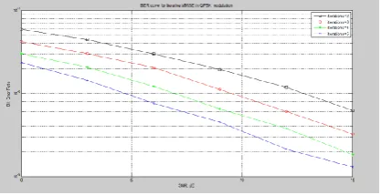
The below figure shows the SNR vs BER plot of the proposed method using the iterative technique for 2,3,4,5 iterations respectively in BPSK and QPSK modulation techniques.
Fig 5. BER curve for minimization of ICI for various
iterations in BPSK modulation.
Fig 6. BER curve for minimization of ICI for various iterations in QPSK modulation.
VI. Conclusion
In this work, the symbol energy distribution and the ICI was analyzed. The effect of these based on time varying multipath channels was observed and a method was proposed to mitigate the effect of ICI with least
computational complexity. The algorithm is
implemented over MIMO-OFDM systems with BPSK
and QPSK constellation. Based on Fast Fourier
Transform, iterative linear MSE has been implemented to maximize the output signal to noise/interference ratio in the MMSE estimates during iterative detection in BPSK and QPSK modulation techniques for 2,3,4&5 iterations by increasing number of iterations bit error is reduced. Finally we achieved a negligible bit error rate in both modulation techniques and in BPSK we observed a less BER compared to QPSK modulation technique.. By using iterative MMSE technique at prescribed signal to noise gain we achieved 𝟏𝟎−𝟗bit error rate .
VII. References
[1]X. Cai and G. B. Giannakis, “Bounding performance and suppressinginter carrier interference in wireless mobile OFDM,” IEEE
Trans.Commun., vol. 51, no. 12, pp. 2047–2056,
Dec. 2003.
[2]B. Muquet, Z. Wang, G. B. Giannakis, M. De Courville, and P. Duhamel, “Cyclic prefixing or
0 2 4 6 8 10 12 14
10-5 10-4 10-3 10-2 10-1
SNR, dB
B
it
E
rr
o
r
R
a
te
Bit error probability curve for BPSK in ICI with MMSE equalizer with L=5
Available online: https://edupediapublications.org/journals/index.php/IJR/ P a g e | 745
zero padding for wireless multicarrier transmissions?” IEEE Trans. Commun., vol. 50, no. 12, pp. 2136–2148, Dec. 2002.
[3]H.-C. Wu, “Analysis and characterization of intercarrier and interblock interferences for wireless mobile OFDM systems,” IEEE Trans.
Broadcast., vol. 52, no. 2, pp. 203–210, Jun. 2006
[4]J. Fu, J. Wang, J. Song, C. Y. Pan, and Z. X. Yang, “A simplified equalization method for dual PN-sequence padding TDS-OFDM systems,”
IEEE Trans. roadcast., vol. 54, no. 4, pp. 825– 830, Dec. 2008.
[5]D. Du, J. Wang, K. Gong, and J. Song, “A transmit diversity scheme for TDS-OFDM system,” IEEE Trans. Broadcast., vol. 54, no. 3, pp. 482–488, Sep. 2008.
[6]A. Stamoulis, S. N. Diggavi, and N. Al-Dhahir, “Intercarrier interference in MIMO OFDM,” IEEE
Trans. Signal Process., vol. 50, no. 10, pp. 2451–
2464, Oct. 2002.
[7]Y. Mostofi and D. C. Cox, “ICI mitigation for pilot-aided OFDM mobile systems,” IEEE Trans.
Wireless Commun., vol. 4, no. 2, pp. 765–774,
Mar. 2005.
[8]W. G. Jeon, K. H. Chang, and Y. S. Cho, “An equalization technique for orthogonal frequency-division multiplexing systems in time-variant multipath channels,” IEEE Trans. Commun., vol. 47, no. 1, pp. 27–32, Jan. 1999.
[9]J. Huang, S. Zhou, and Z. Wang, “Performance results of two iterative receivers for distributed MIMO OFDM with large Doppler deviations,”
IEEE J. Ocean. Eng., vol. 38, no. 2, pp. 347–357,
Apr. 2013.
[10]Q. Sun and D. C. Cox, “Fundamental limits on symbol rate in frequency selective continuous fading channels,” in Proc. IEEE Vehicular Technology Conf., vol. 2, Fall 2001, pp. 1205– 1209.
[11]S. Boyd and L. Vandenberghe, Convex Optimization. Cambridge, U.K.: Cambridge Univ. Press, 2003
[12]A. Oppenheim and R. Schafer, Discrete-Time Signal Processing. Englewood Cliffs, NJ: Prentice-Hall, 1989.
[13]Y. Li and L. Cimini, “Bounds on the inter-channel interference of OFDM in time-varying impairments,” IEEE Trans. Commun., vol. 49, pp. 401–404, Mar. 2001.
[14]B. Li et al., “MIMO-OFDM for high-rate underwater acoustic communications,” IEEE J. Ocean. Eng., vol. 34, no. 4, pp. 634–644, Oct. 2009.
[15]D. D. Lin, R. A. Pacheco, T. J. Lim, and D. atzinakos, “Joint estimation of channel response, frequency offset, and phase noise in OFDM,” IEEE Transactions on signal Processing, vol. 54, no. 9, pp. 3542–3554, September 2006
[16]A. G. Armada and M. Calvo, “Phase noise and sub-carrier spacing effects on the performance of an OFDM communication system,” IEEE Communications Letters, vol. 2, pp. 11–13, Jan 1998.
[17]T. M. Schmidl and D. C. Cox, “Robust frequency and timing synchronization for OFDM,” IEEE Transactions on Communications, vol. 45, no. 12, pp. 1613–1621, December 1997.
![Fig 2 Normalized energy distribution over symbol [9]](https://thumb-us.123doks.com/thumbv2/123dok_us/7732714.1266087/3.595.49.246.131.326/fig-normalized-energy-distribution-symbol.webp)