Design & Development of a Public Key Cryptosystem to
Securely Share Data in Cloud Storage
K.Karthik
1; J.Srinivas
2& Prof.Dr.G.Manoj Someswar
31
M.Tech.(CSE) from Narasimha Reddy Engineering College, Affiliated to JNTUH, Hyderabad,
Telangana, India
2
M.Tech. (CSE), Ph.D., Associate Professor, Department of CSE, Narasimha Reddy Engineering College,
Affiliated to JNTUH, Hyderabad, Telangana, India
3
B.Tech., M.S.(USA), M.C.A., Ph.D., Principal & Professor, Department Of CSE, Anwar-ul-uloom
College of Engineering & Technology, Affiliated to JNTUH, Vikarabad, Telangana, India
ABSTRACT:
Data sharing is an important functionality in cloud storage. In this research paper, we show how to
securely, efficiently, and flexibly share data with others in cloud storage. We describe new public-key
cryptosystems that produce constant-size cipher texts such that efficient delegation of decryption rights for
any set of cipher texts are possible. The novelty is that one can aggregate any set of secret keys and make
them as compact as a single key, but encompassing the power of all the keys being aggregated. In other
words, the secret key holder can release a constant-size aggregate key for flexible choices of cipher text
set in cloud storage, but the other encrypted files outside the set remain confidential. This compact
aggregate key can be conveniently sent to others or be stored in a smart card with very limited secure
storage. We provide formal security analysis of our schemes in the standard model. We also describe
other application of our schemes. In particular, our schemes give the first public-key, patient-controlled
encryption for flexible hierarchy, which was yet to be known.
KEYWORDS:
Infrastructure-as-a-Service (IaaS); Platform-as-a-Service (PaaS); Software-as-a-Service
(SaaS); Provable Data Possession (PDP); Third-Party Auditor (TPA); National Institute of Standards and
Terminology (NIST)
INTRODUCTION
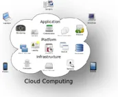
Cloud computing is the use of computing resources (hardware and software) that are delivered as a service over a network (typically the Internet). The name comes from the common use of a cloud-shaped symbol as an abstraction for the complex infrastructure it contains in system diagrams. Cloud computing entrusts remote services with a user's data, software and computation. Cloud computing consists of hardware and software resources made available on the Internet as managed third-party services. These services typically provide access to advanced software applications and high-end networks of server computers.
Figure 1: Structure of cloud computing
personalized information, to provide data storage or to power large, immersive computer games.
The cloud computing uses networks of large groups of servers typically running low-cost consumer PC technology with specialized connections to spread data-processing chores across them. This shared IT infrastructure contains large pools of systems that are linked together. Often, virtualization techniques are used to maximize the power of cloud computing.[1]
Characteristics and Services Models: The salient characteristics of cloud computing based
on the definitions provided by the National Institute of Standards and Terminology (NIST) are outlined below:
On-demand self-service: A consumer can unilaterally provision computing capabilities, such as server time and network storage, as needed automatically without requiring human interaction with each service’s provider.
Broad network access: Capabilities are available over the network and accessed through standard mechanisms that promote use by heterogeneous thin or thick client platforms (e.g., mobile phones, laptops, and PDAs).
Resource pooling: The provider’s computing resources are pooled to serve multiple consumers using a multi-tenant model, with different physical and virtual resources dynamically assigned and reassigned according to consumer demand. There is a sense of location-independence in that the customer generally has no control or knowledge over the exact location of the provided resources but may be able to specify location at a higher level of abstraction (e.g., country, state, or data center). Examples of resources include storage, processing, memory, network bandwidth, and virtual machines.
Rapid elasticity: Capabilities can be rapidly and elastically provisioned, in some cases automatically, to quickly scale out and rapidly released to quickly scale in. To the consumer, the capabilities available for provisioning often appear to be unlimited and can be purchased in any quantity at any time.
Measured service: Cloud systems
automatically control and optimize resource use by leveraging a metering capability at some level of abstraction appropriate to the type of service (e.g., storage, processing, bandwidth, and active user accounts). Resource usage can be managed, controlled, and reported providing transparency for both the provider and consumer of the utilized service. [2]
Figure 2: Characteristics of cloud computing Services Models:
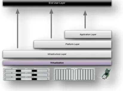
Figure 3: Structure of service models Benefits of cloud computing:
1. Achieve economies of scale – increase volume output or productivity with fewer people. Your cost per unit, project or product plummets.
2. Reduce spending on technology
infrastructure. Maintain easy access to your information with minimal upfront spending. Pay as you go (weekly, quarterly or yearly), based on demand.
3. Globalize your workforce on the cheap. People worldwide can access the cloud, provided they have an Internet connection. 4. Streamline processes. Get more work done in
less time with less people.
5. Reduce capital costs. There’s no need to spend big money on hardware, software or licensing fees.
6. Improve accessibility. You have access anytime, anywhere, making your life so much easier!
7. Monitor projects more effectively. Stay within budget and ahead of completion cycle times.
8. Less personnel training is needed. It takes fewer people to do more work on a cloud, with a minimal learning curve on hardware and software issues.
9. Minimize licensing new software. Stretch and grow without the need to buy expensive software licenses or programs.
10. Improve flexibility. You can change direction without serious “people” or “financial” issues at stake. [4]
Advantages:
1. Price: Pay for only the resources used. 2. Security: Cloud instances are isolated in the
network from other instances for improved security.
3. Performance: Instances can be added
instantly for improved performance. Clients have access to the total resources of the Cloud’s core hardware.
4. Scalability: Auto-deploy cloud instances when needed.
5. Uptime: Uses multiple servers for maximum redundancies. In case of server failure, instances can be automatically created on another server.
6. Control: Able to login from any location. Server snapshot and a software library lets you deploy custom instances.
7. Traffic: Deals with spike in traffic with quick deployment of additional instances to handle the load.[5]
LITERATURE SURVEY
so that users can resort to a third-party auditor (TPA) to check the integrity of outsourced data and be worry free. To securely introduce an effective TPA, the auditing process should bring in no new vulnerabilities toward user data privacy, and introduce no additional online burden to user.[7] In this research paper, we propose a secure cloud storage system supporting privacy-preserving public auditing. We further extend our result to enable the TPA to perform audits for multiple users simultaneously and efficiently. Extensive security and performance analysis show the proposed schemes are provably secure and highly efficient. Our preliminary experiment conducted on Amazon EC2 instance further demonstrates the fast performance of the design.[8]
Nowadays, many organizations outsource data storage to the cloud such that a member (owner) of an organization can easily share data with other members (users). Due to the existence of security concerns in the cloud, both owners and users are suggested to verify the integrity of cloud data with Provable Data Possession (PDP) before further utilization on data.[9] However, previous methods either unnecessarily reveal the identity of a data owner to the untrusted cloud or any public verifiers, or introduce significant overheads on verification metadata to preserve anonymity. In this paper, we propose a simple and efficient publicly verifiable approach to ensure cloud data integrity without sacrificing the anonymity of data owners nor requiring significant verification metadata. Specifically, we introduce a security-mediator (SEM), which is able to generate verification metadata (i.e., signatures) on outsourced data for data owners. Our approach decouples the anonymity protection mechanism from the PDP. Thus, an organization can employ its own anonymous authentication mechanism, and the cloud is oblivious to that since it only deals with typical PDP-metadata, Consequently, there is no extra storage overhead when compared with existing non-anonymous PDP solutions.[10] The distinctive features of our scheme also include data privacy, such that the SEM does not learn anything about the data to
be uploaded to the cloud at all, which is able to minimize the requirement of trust on the SEM.[11] In addition, we can also extend our scheme to work with the multi-SEM model, which can avoid the potential single point of failure existing in the single-SEM scenario. Security analyses prove our scheme is secure, and experiment results demonstrate our scheme is efficient.
One concern in using cloud storage is that the sensitive data should be confidential to the servers which are outside the trust domain of data owners. Another issue is that the user may want to preserve his/her anonymity in the sharing or accessing of the data (such as in Web 2.0 applications). To fully enjoy the benefits of cloud storage, we need a confidential data sharing mechanism which is fine-grained (one can specify who can access which classes of his/her encrypted files), dynamic (the total number of users is not fixed in the setup, and any new user can decrypt previously encrypted messages), scalable (space requirement does not depend on the number of decryptors), accountable (anonymity can be revoked if necessary) and secure (trust level is minimized). This paper addresses the problem of building a secure cloud storage system which supports dynamic users and data provenance. Previous system is based on specific constructions and does not offer all of the aforementioned desirable properties. Most importantly, dynamic user is not supported. We study the various features offered by cryptographic anonymous authentication and encryption mechanisms; and instantiate our design with verifier-local revocable group signature and identity-based broadcast encryption with constant size ciphertext and private keys. To realize our concept, we equip the broadcast encryption with the dynamic ciphertext update feature, and give formal security guarantee against adaptive chosen-ciphertext decryption and update attacks.[12]
obtains access to objects stored at that class and all descendant classes in the hierarchy. The problem of key management for such hierarchies then consists of assigning a key to each class in the hierarchy so that keys for descendant classes can be obtained via efficient key derivation. We propose a solution to this problem with the following properties: (1) the space complexity of the public information is the same as that of storing the hierarchy; (2) the private information at a class consists of a single key associated with that class; (3) updates (i.e., revocations and additions) are handled locally in the hierarchy; (4) the scheme is provably secure against collusion; and (5) each node can derive the key of any of its descendant with a number of symmetric-key operations bounded by the length of the path between the nodes.[13] Whereas many previous schemes had some of these properties, ours is the first that satisfies all of them. The security of our scheme is based on pseudorandom functions, without reliance on the Random Oracle Model. Another substantial contribution of this work is that we are able to lower the key derivation time at the expense of modestly increasing the public storage associated with the hierarchy. Insertion of additional, so-called shortcut, edges, allows to lower the key derivation to a small constant number of steps for graphs that are total orders and trees by increasing the total number of edges by a small asymptotic factor such as O(log* n) for an n-node hierarchy.[14] For more general access hierarchies of dimension d, we use a technique that consists of adding dummy nodes and dimension reduction. The key derivation work for such graphs is then linear in d and the increase in the number of edges is by the factor O (log d − 1 n) compared to the one-dimensional case. Finally, by making simple modifications to our scheme, we show how to handle extensions proposed by Crampton [2003] of the standard hierarchies to “limited depth” and reverse inheritance.
As more sensitive data is shared and stored by third-party sites on the Internet, there will be a need to
encrypt data stored at these sites. One drawback of encrypting data, is that it can be selectively shared only at a coarse-grained level (i.e., giving another party your private key). We develop a new cryptosystem for fine-grained sharing of encrypted data that we call Key-Policy Attribute-Based Encryption (KP-ABE).[15] In our cryptosystem, cip hertexts are labeled with sets of attributes and private keys are associated with access structures that control which ciphertexts a user is able to decrypt.
SYSTEM STUDY FEASIBILITY STUDY
The feasibility of the project is analyzed in this phase and business proposal is put forth with a very general plan for the project and some cost estimates. During system analysis the feasibility study of the proposed system is to be carried out. This is to ensure that the proposed system is not a burden to the company. For feasibility analysis, some understanding of the major requirements for the system is essential.
Three key considerations involved in the feasibility analysis are
ECONOMICAL FEASIBILITY
TECHNICAL FEASIBILITY
SOCIAL FEASIBILITY ECONOMICAL FEASIBILITY
This study is carried out to check the economic impact that the system will have on the organization. The amount of fund that the company can pour into the research and development of the system is limited. The expenditures must be justified. Thus the developed system as well within the budget and this was achieved because most of the technologies used are freely available. Only the customized products had to be purchased.
TECHNICAL FEASIBILITY
resources. This will lead to high demands being placed on the client. The developed system must have a modest requirement, as only minimal or null changes are required for implementing this system.
SOCIAL FEASIBILITY
The aspect of study is to check the level of acceptance of the system by the user. This includes the process of training the user to use the system efficiently. The user must not feel threatened by the system, instead must accept it as a necessity. The level of acceptance by the users solely depends on the methods that are employed to educate the user about the system and to make him familiar with it. His level of confidence must be raised so that he is also able to make some constructive criticism, which is welcomed, as he is the final user of the system.
SYSTEM DESIGN SYSTEM ARCHITECTURE:
Figure 4: System Architecture
BLOCK DIAGRAM:
Figure 5: Block Diagram DATA FLOW DIAGRAM:
1. The DFD is also called as bubble chart. It is a simple graphical formalism that can be used to represent a system in terms of input data to the system, various processing carried out on this data, and the output data is generated by this system.
2. The data flow diagram (DFD) is one of the most important modeling tools. It is used to model the system components. These components are the system process, the data used by the process, an external entity that interacts with the system and the information flows in the system.
3. DFD shows how the information moves through the system and how it is modified by a series of transformations. It is a graphical technique that depicts information flow and the transformations that are applied as data moves from input to output.
4. DFD is also known as bubble chart. A DFD may be used to represent a system at any level of abstraction. DFD may be partitioned into levels that represent increasing information flow and functional detail.
Cloud
User 1 Generate Aggregate key and send User 2 Key generate and
encrypt content Upload to cloud
Download encrypt content
Decrypt content
Figure 6: Data Flow Diagram UML DIAGRAMS
UML stands for Unified Modeling Language. UML is a standardized general-purpose modeling language in the field of object-oriented software engineering. The standard is managed, and was created by, the Object Management Group.
The goal is for UML to become a common language for creating models of object oriented computer software. In its current form UML is comprised of two major components: a Meta-model and a notation. In the future, some form of method or process may also be added to; or associated with, UML.
The Unified Modeling Language is a standard language for specifying, Visualization, Constructing and documenting the artifacts of software system, as well as for business modeling and other non-software systems.
The UML represents a collection of best engineering practices that have proven successful in the modeling of large and complex systems.
The UML is a very important part of developing objects oriented software and the software development process. The UML uses mostly graphical notations to express the design of software projects. GOALS:
The Primary goals in the design of the UML are as follows:
1. Provide users a ready-to-use, expressive visual modeling Language so that they can develop and exchange meaningful models.
2. Provide extendibility and specialization mechanisms to extend the core concepts.
3. Be independent of particular programming languages and development process.
4. Provide a formal basis for understanding the modeling language.
5. Encourage the growth of OO tools market. 6. Support higher level development concepts
such as collaborations, frameworks, patterns and components.
7. Integrate best practices. USE CASE DIAGRAM:
A use case diagram in the Unified Modeling Language (UML) is a type of behavioral diagram defined by and created from a Use-case analysis. Its purpose is to present a graphical overview of the functionality provided by a system in terms of actors, their goals (represented as use cases), and any dependencies between those use cases. The main purpose of a use case diagram is to show what system functions are performed for which actor. Roles of the actors in the system can be depicted.
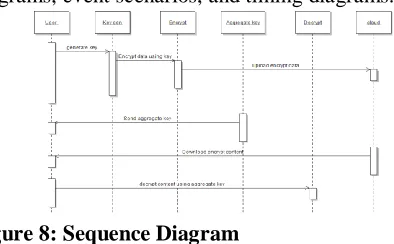
Figure 7: Use Case Diagram SEQUENCE DIAGRAM:
A sequence diagram in Unified Modeling Language (UML) is a kind of interaction diagram that shows how processes operate with one another and in what order. It is a construct of a Message Sequence Chart. Sequence diagrams are sometimes called event diagrams, event scenarios, and timing diagrams.
Figure 8: Sequence Diagram
User
Key generates and encrypts content Upload to cloud
Download encrypt content
Decrypt content
Using Aggregate key Upload Download
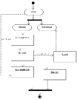
ACTIVITY DIAGRAM:
Activity diagrams are graphical representations of workflows of stepwise activities and actions with support for choice, iteration and concurrency. In the Unified Modeling Language, activity diagrams can be used to describe the business and operational step-by-step workflows of components in a system. An activity diagram shows the overall flow of control.
Figure 9: Activity Diagram INPUT DESIGN
The input design is the link between the information system and the user. It comprises the developing specification and procedures for data preparation and those steps are necessary to put transaction data in to a usable form for processing can be achieved by inspecting the computer to read data from a written or printed document or it can occur by having people keying the data directly into the system. The design of input focuses on controlling the amount of input required, controlling the errors, avoiding delay, avoiding extra steps and keeping the process simple. The input is designed in such a way so that it provides security and ease of use with retaining the privacy. Input Design considered the following things:
What data should be given as input?
How the data should be arranged or coded?
The dialog to guide the operating personnel in providing input.
Methods for preparing input validations and steps to follow when error occur.
OBJECTIVES
1. Input Design is the process of converting a user-oriented description of the input into a computer-based system. This design is important to avoid errors in the data input process and show the correct direction to the management for getting correct information from the computerized system.
2. It is achieved by creating user-friendly screens for the data entry to handle large volume of data. The goal of designing input is to make data entry easier and to be free from errors. The data entry screen is designed in such a way that all the data manipulates can be performed. It also provides record viewing facilities. 3. When the data is entered it will check for its validity. Data can be entered with the help of screens. Appropriate messages are provided as when needed so that the user will not be in maize of instant. Thus the objective of input design is to create an input layout that is easy to follow
OUTPUT DESIGN
A quality output is one, which meets the requirements of the end user and presents the information clearly. In any system results of processing are communicated to the users and to other system through outputs. In output design it is determined how the information is to be displaced for immediate need and also the hard copy output. It is the most important and direct source information to the user. Efficient and intelligent output design improves the system’s relationship to help user decision-making.
1. Designing computer output should proceed in an organized, well thought out manner; the right output must be developed while ensuring that each output element is designed so that people will find the system can use easily and effectively. When analysis design computer output, they should Identify the specific output that is needed to meet the requirements.
3. Create document, report, or other formats that contain information produced by the system.
The output form of an information system should accomplish one or more of the following objectives.
Convey information about past activities, current status or projections of the
Future.
Signal important events, opportunities, problems, or warnings.
Trigger an action.
Confirm an action.
SYSTEM ANALYSIS EXISTING SYSTEM:
Considering data privacy, a traditional way to ensure it is to rely on the server to enforce the access control after authentication, which means any unexpected privilege escalation will expose all data. In a shared-tenancy cloud computing environment, things become even worse.
Regarding availability of files, there are a series of cryptographic schemes which go as far as allowing a third-party auditor to check the availability of files on behalf of the data owner without leaking anything about the data, or without compromising the data owners anonymity. Likewise, cloud users probably will not hold the strong belief that the cloud server is doing a good job in terms of confidentiality.
A cryptographic solution, with proven security relied on number-theoretic assumptions is more desirable, whenever the user is not perfectly happy with trusting the security of the VM or the honesty of the technical staff.
DISADVANTAGES OF EXISTING SYSTEM: 1. The costs and complexities involved generally increase with the number of the decryption keys to be shared.
2. The encryption key and decryption key are different in publickey encryption.
PROPOSED SYSTEM:
In this research paper, we study how to make a decryption key more powerful in the sense that it allows decryption of multiple ciphertexts, without
increasing its size. Specifically, our problem statement is “To design an efficient public-key encryption scheme which supports flexible delegation in the sense that any subset of the ciphertexts (produced by the encryption scheme) is decry ptable by a constant-size decryption key (generated by the owner of the master-secret key).” We solve this problem by introducing a special type of public-key encryption which we call key-aggregate cryptosystem (KAC). In KAC, users encrypt a message not only under a public-key, but also under an identifier of ciphertext called class. That means the ciphertexts are further categorized into different classes. The key owner holds a master-secret called master-secret key, which can be used to extract secret keys for different classes. More importantly, the extracted key have can be an aggregate key which is as compact as a secret key for a single class, but aggregates the power of many such keys, i.e., the decryption power for any subset of ciphertext classes. ADVANTAGES OF PROPOSED SYSTEM:
1. The extracted key have can be an aggregate key which is as compact as a secret key for a single class.
2. The delegation of decryption can be efficiently implemented with the aggregate key.
SYSTEM TESTING
The purpose of testing is to discover errors. Testing is the process of trying to discover every conceivable fault or weakness in a work product. It provides a way to check the functionality of components, sub assemblies, assemblies and/or a finished product It is the process of exercising software with the intent of ensuring that the Software system meets its requirements and user expectations and does not fail in an unacceptable manner. There are various types of test. Each test type addresses a specific testing requirement.
TYPES OF TESTS Unit testing
outputs. All decision branches and internal code flow should be validated. It is the testing of individual software units of the application .it is done after the completion of an individual unit before integration. This is a structural testing, that relies on knowledge of its construction and is invasive. Unit tests perform basic tests at component level and test a specific business process, application, and/or system configuration. Unit tests ensure that each unique path of a business process performs accurately to the documented specifications and contains clearly defined inputs and expected results.
Integration testing
Integration tests are designed to test integrated software components to determine if they actually run as one program. Testing is event driven and is more concerned with the basic outcome of screens or fields. Integration tests demonstrate that although the components were individually satisfaction, as shown by successfully unit testing, the combination of components is correct and consistent. Integration testing is specifically aimed at exposing the problems that arise from the combination of components.
Functional test
Functional tests provide systematic demonstrations that functions tested are available as specified by the business and technical requirements, system documentation, and user manuals.
Functional testing is centered on the following items: Valid Input : identified classes of valid input must be accepted.
Invalid Input : identified classes of invalid input must be rejected.
Functions : identified functions must be exercised.
Output : identified classes of application outputs must be exercised.
Systems/Procedures: interfacing systems or procedures must be invoked.
Organization and preparation of functional tests is focused on requirements, key functions, or special test cases. In addition, systematic coverage pertaining to
identify Business process flows; data fields, predefined processes, and successive processes must be considered for testing. Before functional testing is complete, additional tests are identified and the effective value of current tests is determined.
System Test
System testing ensures that the entire integrated software system meets requirements. It tests a configuration to ensure known and predictable results. An example of system testing is the configuration oriented system integration test. System testing is based on process descriptions and flows, emphasizing pre-driven process links and integration points.
White Box Testing
White Box Testing is a testing in which in which the software tester has knowledge of the inner workings, structure and language of the software, or at least its purpose. It is purpose. It is used to test areas that cannot be reached from a black box level.
Black Box Testing
Black Box Testing is testing the software without any knowledge of the inner workings, structure or language of the module being tested. Black box tests, as most other kinds of tests, must be written from a definitive source document, such as specification or requirements document, such as specification or requirements document. It is a testing in which the software under test is treated, as a black box .you cannot “see” into it. The test provides inputs and responds to outputs without considering how the software work.
Unit Testing:
Unit testing is usually conducted as part of a combined code and unit test phase of the software lifecycle, although it is not uncommon for coding and unit testing to be conducted as two distinct phases. Test strategy and approach
Field testing will be performed manually and functional tests will be written in detail.
Test objectives
Pages must be activated from the identified link.
The entry screen, messages and responses must not be delayed.
Features to be tested
Verify that the entries are of the correct format
No duplicate entries should be allowed
All links should take the user to the correct page.
Integration Testing
Software integration testing is the incremental integration testing of two or more integrated software components on a single platform to produce failures caused by interface defects.
The task of the integration test is to check that components or software applications, e.g. components in a software system or – one step up – software applications at the company level – interact without error.
Test Results: All the test cases mentioned above passed successfully. No defects encountered.
Acceptance Testing
User Acceptance Testing is a critical phase of any project and requires significant participation by the end user. It also ensures that the system meets the functional requirements.
Test Results: All the test cases mentioned above passed successfully. No defects encountered.
IMPLEMENTATION MODULES:
1. Data Owner(Alice) 2. Network Storage 3. Aggregate Key Transfer 4. User(Bob)
MODULES DESCRIPTION: Data Owner (Alice):
In this module we executed by the data owner to setup an account on an untrusted server. On input a security level parameter 1λ and the number of ciphertext classes n (i.e., class index should be an integer bounded by 1 and n), it outputs the public system parameter param,
which is omitted from the input of the other algorithms for brevity.
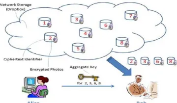
Network Storage (Drop box):
With our solution, Alice can simply send Bob a single aggregate key via a secure e-mail. Bob can download the encrypted photos from Alice’s Dropbox space and then use this aggregate key to decrypt these encrypted photos. In this Network Storage is untrusted third party server or dropbox.
Aggregate Key Transfer:
A key-aggregate encryption scheme consists of five polynomial-time algorithms as follows. The data owner establishes the public system parameter via Setup and generates a public/master-secret key pair via KeyGen. Messages can be encrypted via Encrypt by anyone who also decides what ciphertext class is asso-ciated with the plaintext message to be encrypted. The data owner can use the master-secret to generate an aggregate decryption key for a set of ciphertext classes via Extract. The generated keys can be passed to delegates securely (via secure e-mails or secure devices) finally; any user with an aggregate key can decrypt any ciphertext provided that the ciphertext’s class is contained in the aggregate key via Decrypt User (Bob):
The generated keys can be passed to delegates securely (via secure e-mails or secure devices) finally; any user with an aggregate key can decrypt any ciphertext provided that the ciphertext’s class is contained in the aggregate key via Decrypt.
RESULTS & CONCLUSION
spaces if all key-holders share a similar set of privileges. A limitation in our work is the predefined bound of the number of maximum ciphertext classes. In cloud storage, the number of ciphertexts usually grows rapidly. So we have to reserve enough ciphertext classes for the future extension.
Although the parameter can be downloaded with ciphertexts, it would be better if its size is independent of the maximum number of ciphertext classes. On the other hand, when one carries the delegated keys around in a mobile device without using special trusted hardware, the key is prompt to leakage, designing a leakage-resilient cryptosystem [22], [34] yet allows efficient and flexible key delegation is also an interesting direction.
REFERENCES
[1] S.S.M. Chow, Y.J. He, L.C.K. Hui, and S.-M. Yiu, “SPICE – Simple Privacy-Preserving Identity-Management for Cloud Environment,” Proc. 10th Int’l Conf. Applied Cryptography and Network Security (ACNS), vol. 7341, pp. 526-543, 2012.
[2] L. Hardesty, Secure Computers Aren’t so Secure. MIT press, http://www.physorg.com/news176107396.html, 2009.
[3] C. Wang, S.S.M. Chow, Q. Wang, K. Ren, and W. Lou, “Privacy-Preserving Public Auditing for Secure Cloud Storage,” IEEE Trans. Computers, vol. 62, no. 2, pp. 362-375, Feb. 2013.
[4] B. Wang, S.S.M. Chow, M. Li, and H. Li, “Storing Shared Data on the Cloud via Security-Mediator,” Proc. IEEE 33rd Int’l Conf. Distributed Computing Systems (ICDCS), 2013.
[5] S.S.M. Chow, C.-K. Chu, X. Huang, J. Zhou, and R.H. Deng, “Dynamic Secure Cloud Storage with Provenance,” Cryptography and Security, pp. 442-464, Springer, 2012.
[6] D. Boneh, C. Gentry, B. Lynn, and H. Shacham, “Aggregate and Verifiably Encrypted Signatures from
Bilinear Maps,” Proc. 22nd
Int’l Conf. Theory and Applications of Cryptographic Techniques (EUROCRYPT ’03), pp. 416-432, 2003.
[7] M.J. Atallah, M. Blanton, N. Fazio, and K.B. Frikken, “Dynamic and Efficient Key Management for Access Hierarchies,” ACM Trans. Information and System Security, vol. 12, no. 3, pp. 18:1-18:43, 2009.
[8] J. Benaloh, M. Chase, E. Horvitz, and K. Lauter, “Patient Controlled Encryption: Ensuring Privacy of Electronic Medical Records,” Proc. ACM Workshop Cloud Computing Security (CCSW ’09), pp. 103-114, 2009.
[9] F. Guo, Y. Mu, Z. Chen, and L. Xu, “Multi-Identity Single-Key Decryption without Random Oracles,” Proc. Information Security and Cryptology (Inscrypt ’07), vol. 4990, pp. 384-398, 2007.
[10] V. Goyal, O. Pandey, A. Sahai, and B. Waters, “Attribute-Based Encryption for Fine-Grained Access Control of Encrypted Data,” Proc. 13th ACM Conf. Computer and Comm. Security (CCS ’06), pp. 89-98, 2006.
[11] S.G. Akl and P.D. Taylor, “Cryptographic Solution to a Problem of Access Control in a Hierarchy,” ACM Trans. Computer Systems, vol. 1, no. 3, pp. 239-248, 1983.
[12] G.C. Chick and S.E. Tavares, “Flexible Access Control with Master Keys,” Proc. Advances in Cryptology (CRYPTO ’89), vol. 435, pp. 316-322, 1989.
[13] W.-G. Tzeng, “A Time-Bound Cryptographic Key Assignment Scheme for Access Control in a Hierarchy,” IEEE Trans. Knowledge and Data Eng., vol. 14, no. 1, pp. 182-188, Jan./Feb. 2002.
[14] G. Ateniese, A.D. Santis, A.L. Ferrara, and B. Masucci,
“Provably-Secure Time-Bound Hierarchical Key
Assignment Schemes,” J. Cryptology, vol. 25, no. 2, pp. 243-270, 2012.