!
"
#
$#$
!% & &$
'
(
))) *
DSR Versus Reactive ZRP: A Comparative Study with Time Process and Time
Consumed in Data Transmission
N. Koteswar Rao*
Associate Professor,
Dept. of IT, Narayana Engineering College, Gudur, AP, India.
B.Mohan Associate Professor,
Dept. of CSE, Narayana Engineering College, Gudur, AP, India.
J.Venkata Prasad Associate Professor,
Dept. of CSE, Narayana Engineering College, Gudur, AP, India.
K.Venkateswarlu Asst. Professor & HOD, Dept. of ECE, MeRITS, Udayagiri, AP, India. [email protected]
Abstract:The Dynamic Source Routing (DSR) is a reactive unicast routing protocol that utilizes source routing algorithm. In source routing algorithm, each data packet contains complete routing information to reach its dissemination. Additionally, in DSR each node uses caching technology to maintain route information that it has learnt. The Zone Routing Protocol (ZRP) is a hybrid routing protocol for mobile ad hoc networks. The hybrid protocols are proposed to reduce the control overhead of proactive routing approaches and decrease the latency caused by route search operations in reactive routing approaches. In this paper we discussed the effectiveness of a Reactive Zone Routing Protocol(RZRP) through a simulation of sending and receiving of information in a timely based by comparing with DSR protocol. Simulation results shows the Time Process and Time Consumed for both protocols in several cases.
Keywords: RZRP, Intrazone Routing Protocol, Interzone Routing Protocol, DSR, Time Process, Time Consumed.
I. INTRODUCTION
The advancement in mobile portable computing devices such as laptops, personal digital assistants and the advancements in wireless communication have made mobile computing possible and inevitable. One research area that has attracted the attention of scientific community recently is the mobile ad hoc network (MANET). A MANET is formed by a group of portable devices (nodes) having almost same functionality. It can be quickly deployed without any infrastructure or centralized administration. Each node acts as a store and forward station for routing packets. Nodes are required to deliver packets to the correct destinations. Two nodes wishing to communicate can do so directly if they are within the radio range of each other or route their packets through other nodes. [1]
The functionality difference of MANET from traditional wired internet introduces unique challenges such as node mobility, unpredictable link properties, limited battery life etc. As the nodes are highly dynamic, maintaining routes become a greater challenge. Further, nodes may join and leave the network at any time. Thus the routing
algorithm must maintain and reconstruct the routing paths with minimal overhead and delay. [5]
In general, the existing routing protocols can be classified either as proactive or as reactive. Proactive protocols attempt to continuously evaluate the routes within the network, so that when a packet needs to be forwarded, the route is already known and can be immediately used. The
family of Distance-Vector protocols is an example of a proactive scheme. Examples of proactive routing protocols include the Wireless Routing Protocol (WRP) and Destination-Sequenced Distance-Vector (DSDV) routing. Reactive protocols, on the other hand, invoke a route determination procedure on demand only. Thus, when a route is needed, some sort of global search procedure is employed. The family of classical flooding algorithms belong to the reactive group. Some other examples of reactive (also called on-demand) ad hoc network routing protocols are Dynamic Source Routing (DSR), Ad-hoc On demand Distance Vector Routing (AODV) and the Temporally Ordered Routing Algorithm (TORA).[5][7]
II. DYNAMIC SOURCE ROUTING
The Dynamic Source Routing (DSR) protocol is a simple and efficient routing protocol designed specifically for use in multi-hop wireless ad hoc networks of mobile nodes. It is based on the concept of source routing, a routing technique in which the sender of the packet determines the complete sequence of the nodes through which to forward the packet. The sender explicitly lists this route in the packet’s header, identifying each forwarding “hop” by the address of the next node to which to transmit the packet on its way to the destination host.
packet. Otherwise, it will initiate route discovery by broadcasting a route request packet. When receiving a request packet, a node appends its own address to the route record in the route request packet if it did not receive this request message before, and re-broadcasts the query to its neighbors. Alternatively, it will send a reply packet to the source without propagating the query packet further if it can complete the query from its route cache. Furthermore, any node participating in route discovery can learn routes from passing packets and gather this routing information into its route cache. Figure 1 shows route discovery of DSR. Node 2 is the initiator and node 9 is the target.[5]
Figure 1: Route Discovery in DSR
When sending or forwarding a packet to a destination, Route Maintenance is used to detect if the network topology has changed such that the link used by this packet is broken. Each node along the route, when transmitting the packet to the next hop, is responsible for detecting if its link to the next hop has broken. When the retransmission and acknowledgement mechanism detects that the link is broken, the detecting node returns a Route Error packet to the source of the packet. The node will then search its route cache to find if there is an alternative route to the destination of this packet. If there is one, the node will change the source route in the packet header and send it using this new route. This mechanism is called “salvaging” a packet. When a Route Error packet is received or overheard, the link in error is removed from the local route cache, and all routes which contain this hop must be truncated at that point. The source can then attempt to use any other route to the destination that is already in its route cache, or can invoke Route Discovery again to find a new route.[7]
III. ZONE ROUTING PROTOCOL( ZRP)
Proactive routing uses excess bandwidth to maintain routing information, while reactive routing involves long route request delays. Reactive routing also inefficiently floods the entire network for route determination. The Zone Routing Protocol (ZRP) aims to address the problems by combining the best properties of both approaches. ZRP can be classed as a hybrid reactive/proactive routing protocol.
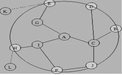
The Zone Routing Protocol, as its name implies, is based on the concept of zones. A routing zone is defined for each node separately, and the zones of neighboring nodes overlap. The routing zone has a radius ρ expressed in hops. The zone thus includes the nodes, whose distance from the node in question is at most ρ hops. An example routing zone is shown in Figure 2, where the routing zone of S includes the
[image:2.612.320.519.106.229.2]nodes A–I, but not K. In the illustrations, the radius is marked as a circle around the node in question. It should however be noted that the zone is defined in hops, not as a physical distance.[2][1]
Figure 2: Routing Zone of node A with ρ=2
The nodes of a zone are divided into peripheral nodes and interior nodes. Peripheral nodes are nodes whose minimum distance to the central node is exactly equal to the zone radius ρ. The nodes whose minimum distance is less than ρ are interior nodes. In Figure 1, the nodes A–F are interior nodes, the nodes G–J are peripheral nodes and the node K is outside the routing zone. Note that node H can be reached by two paths, one with length 2 and one with length 3 hops. The node is however within the zone, since the shortest path is less than or equal to the zone radius.
The number of nodes in the routing zone can be regulated by adjusting the transmission power of the nodes. Lowering the power reduces the number of nodes within direct reach and vice versa. The number of neighboring nodes should be sufficient to provide adequate reachability and redundancy. On the other hand, a too large coverage results in many zone members and the update traffic becomes excessive. Further, large transmission coverage adds to the probability of local contention.
ZRP refers to the locally proactive routing component as the IntrA-zone Routing Protocol (IARP). The globally reactive routing component is named IntEr-zone Routing Protocol (IERP). IERP and IARP are not specific routing protocols. Instead, IARP is a family of limited-depth, proactive link-state routing protocols. IARP maintains routing information for nodes that are within the routing zone of the node. correspondingly, IERP is a family of reactive routing protocols that offer enhanced route discovery and route maintenance services based on local connectivity monitored by IARP. [2][3]
IV. REACTIVE ZONE ROUTING PROTOCOL(RZRP)
The structures of major control packets used in RZRP are as follow:
• Interzone RREQ: <RREQ_ID, SourceNode_ID,
SourceZone_ID, DestNode_ID, NeighbouringZone_List, RouteZone_List> where RREQ_ID and SourceNode_ID are used to identify this packet. NeighbouringZone_List is the list contains IDs of neighbouring zones which currently connected with. Finally, the RouteZone_List contains the IDs of zones which will be used to forward this packet.
• Intrazone RREQ: <RREQ_ID, InitiatorNode_ID,
Route_List> where LastHop_Location is reserved for future using which contains location information about the last hop node. Route_List contains a set of nodes which will be used to forward this packet.
• Interzone RREP: <RREP_ID, ReplierNode_ID, Route_List> where Route_List contains the complete path between source node and destination node in zone-to-zone manner.
• Intrazone RREP: <RREP_ID, ReplierNode_ID, ReplierZone_ID, Route_List> where
ReplierZone_ID tells the initiator that which zone it has connected with. Route_List is the
complete path to the replier’s zone in node-to-node manner. [8][3]
When a source node wants to transmit packets to a destination node, it firstly checks its cache, if there is no valid path it then initiates an Intrazone RREQ. If the Intrazone RREQ cannot find the destination node in the same zone, an Interzone RREQ is then initiated and sent out to neighbouring zones by source node following the paths established by Intrazone RREQ. When a node receives an Interzone RREQ, it processes the packet following the pseudo code in Procedure 1. The first node in the zone receives an Interzone RREQ from its neighbouring zone and finds there are no valid paths to its other neighbouring zones or destination node it then initiates an Intrazone RREQ. When a node receives an Intrazone RREQ, it processes the packet following the pseudo code in Procedure 2. The Interzone RREQ will be forwarded when the node receives Intrazone RREPs to confirm the connectivity from its neighbouring zones. In such a manner, a route can be found as illustrated in the figure aside. Once the route between source node and destination node is established, the source node put the complete route in zone-to-zone manner into the data packet’s header and sends it to the next-hop zone following the routing path in its cache. If a node detects its next-hop neighbour is no longer available it will select another path to the same neighbouring zone, if no such path can be found in its cache, it then initiates another Intrazone RREQ.
Procedure processInterRREQ (InterRREQ packet) {
If (myPktTable.contains(packet)==false){ addToMyPktTable(packet);
If(myNode_ID == packet.DestNode_ID || findPath(DestNode_ID)!=null) {
send(Interzone_RREP); }
else if (findPath(Neigh_Zones)!=null) {forward(packet); } else if
(packet.Route_List.contains(myZone_ID)==false{ addMyZoneID(packet.Route_List);
initiate(myIntrazone_RREQ);}
else if (packet.Route_List.contains(myZone_ID)){ drop(packet);}
} else drop(packet); }
“Procedure 1 Processing Interzone RREQ”
Procedure processIntraRREQ (IntraRREQ packet) {
If(myPktTable.contains(packet.pkt_ID)==false){
If(myNode_ID==packet.DestNode_ID) {
send(Interzone RREP);} else {
If(myZone_ID==packet.InitiatorZone_ID){ Path P = findPath(DestNode_ID);
If (P!=null) {
send(Interzone_RREP);}
else forward(packet);}
else send(Intrazone_RREP);} }
else {
If(packet.Route_List.contains(myNode_ID) { drop(packet);}
else updateMyCache(packet.Route_List); } }
“Procedure 2 Processing Intrazone RREQ”
V. RESULTS ANALYSIS AND SIMULATION WORK
Assume that the data connection speed (transfer rate) in this simulation is considered to be the same on each link. Parameters used in the Simulation:
1. Time Process
2. Time Consumed
Case 1(a): is the case in which Bluetooth equipped devices are each sending a packet of data to one specific node. The complete data can be found in the attachments but the means results are as follows:
Figure 1
Figure 2
Case 1a. Mean of Time Process Comparison Graph
0 50 100 150 200 250 300 350 400
10 15 17 18 20 25 30 35 40 50
Number of Nodes
T
im
e DSR Time Process
ZRP Time Process
Case 1a. Mean of Time Consumed Comparison Graph
0 100 200 300 400 500
10 15 17 18 20 25 30 35 40 50
Number of Nodes
T
im
e DSR Time Consumed
Case 1(b):is the case with a different condition in which the destination node is located on the middle of the topology (please refer to the topology figures on the attachments). And the results are as follows:
Figure 3
Figure 4
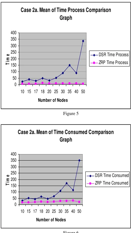
Case 2(a): is very much different in the first two cases. In this case one node that is located at the very end of the network topology is sending packet to all the nodes in the topology. We will see the big difference as follows:
[image:4.612.320.534.61.439.2]
Figure 5
Figure 6
Case 2(b): will give us a description when the source node is located in the middle of the network topology. And the results are as follows:
Figure 7
Case 2b. Mean of Time Process Comparison Graph
0 50 100 150 200 250 300
10 15 17 18 20 25 30 35 40 50
Number of Nodes
T
im
e DSR Time Process
ZRP Time Process
Case 2a. Mean of Time Consumed Comparison Graph
0 50 100 150 200 250 300 350 400
10 15 17 18 20 25 30 35 40 50
Number of Nodes
T
im
e DSR Time Consumed
ZRP Time Consumed
Case 2a. Mean of Time Process Comparison Graph
0 50 100 150 200 250 300 350 400
10 15 17 18 20 25 30 35 40 50
Number of Nodes
T
im
e DSR Time Process
ZRP Time Process
Case 1b. Mean of Time Consumed Comparison Graph
0 50 100 150 200
10 15 17 18 20 25 30 35 40 50
Number of Nodes
T
im
e DSR Time Consumed
ZRP Time Consumed Case 1b. Mean of Time Process Comparison
Graph
0 20 40 60 80 100 120 140 160
10 15 17 18 20 25 30 35 40 50
Number of Nodes
T
im
e DSR Time Process
[image:4.612.323.547.512.649.2][image:5.612.54.276.276.430.2]
Figure 8
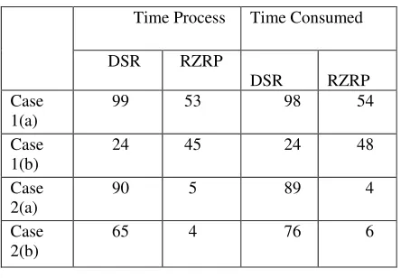
Table I: Comparison between DSR and RZRP
Time Process Time Consumed
DSR RZRP DSR
RZRP Case
1(a)
99 53 98 54
Case 1(b)
24 45 24 48
Case 2(a)
90 5 89 4
Case 2(b)
65 4 76 6
VI. CONCLUSION & FUTURE WORK
Since in all 4 subcases, Reactive Zone Routing Protocol shows better performance in 3 of them (case 1a, case 2a, and case 2b), we should give consideration on using the protocol for a large network topology. Although then we should also consider on increasing the budget due to the needs of using a server for operating under this protocol.
There should be a further learning process on how to develop a switching software that can switch between routing schemes according to location of source, destination, and also according to both types of network topology.
VII. REFERENCES
[1] Pearlman, Marc R., Haas, Zygmunt J.: Determining the Optimal Configuration for the Zone Routing Protocol, August 1999, IEEE Journal on Selected Areas in ommunications, Vol. 17, No. 8
[2] Z. J. Haas and M. R. Pearlman, “The Zone Routing Protocol (ZRP) for Ad-Hoc Networks”, IETF MANET draft, 2003.
[3] Haas, Zygmunt J., Pearlman, Marc R., Samar, P.: Interzone Routing Protocol (IERP), June 2001, IETF Internet Draft, draft-ietf-manet-ierp-01.txt
[4] T. Park, K-G. Shine, “Optimal Tradeoffs for Location-Based Routing In Large-Scale Ad Hoc Networks”, IEEE/ACM Transactions on Networking, Volume 13 Issue 2, April 2005.
[5] YUAN Peiyan, LI Layuan, “Performance Evaluation and Simulations of Routing Protocols in Ad Hoc Networks”, ACM 2006.
[6] Lan Wang and Stephan Olariu, “A Two-Zone Hybrid Routing Protocol for Mobile Ad Hoc Networks”, IEEE 2004.
[7] C. Siva Ram Murthy and B.S. Manoj. Ad Hoc Wireless Networks: Architectures and Protocols, Pearson Education.
[8] Z. J. Haas and M. R. Pearlman. “The performance of query control schemes for the zone routing protocol.” in Proceedings of the ACMSIGCOMM ’98, pages 167– 177. ACM Press, 1998.
IX. ABOUT AUTHORS
1. Mr. N.Koteswar Rao, received his B.Tech from Narayana Engineering College, Nellore and M.Tech in IT from Sathyabama University, Chennai. Presently he is working as Associate Professor in the dept. of IT at Narayana Engineering College, Gudur, AP, India. He has published several papers in various International & National Conferences and Journals. His research interests include Computer Networks and Mobile Ad-Hoc Networks.
2. Mr. B.Mohan, received M.Tech in CSE from JNTU, Hyderabad. Presently he is working as Associate Professor and HOD of CSE at Narayana Engineering College, Gudur, AP, India. He has published several papers in various International & National Conferences and Journals. His research interests include Computer Networks and Mobile Ad-Hoc Networks.
3. Mr. J.V.Prasad, received his B.Tech from Intel Engineering College, Anantapur and M.Tech in IT from Sathyabama University, Chennai. Presently he is working as Associate Professor in the dept. of CSE at Narayana Engineering College, Gudur, AP, India. His research interests include Data Mining and Mobile Ad-Hoc Networks.
4.Mr.K.Venkateswarlu, received his B.Tech from N.B.K.R. Institute of Technology & Science, Vidyanagar, AP and M.Tech from JNTU Anantapur. He is working as Asst.Professor and HOD, ECE at Mekapati Rajamohan Reddy Institute of Technology & Science, Udayagiri, AP, India.
Case 2b. Mean of Time Consumed Comparison Graph
0 50 100 150 200 250 300
10 15 17 18 20 25 30 35 40 50
Number of Nodes
T
im
e DSR Time Consumed