892 | P a g e
EXPERIMENT ON HEAT DISSIPATION IN
INTERNAL COMBUSTION ENGINE BLOCK FINS
WITH & WITHOUT COPPER WINDING
P. Raja
1, B. Srinivasan
2, M. Karunakara Raja
3,
B. Subha Praveen
4, P. Srinath
51,2,3,4.
Under graduate Students,
5.Post graduate student
1,2,3,4,5
Department of Mechanical Engineering,
1,2,3,4.
Sri Krishna College of Engineering and Technology,
5.
Sri Ramakrishna Engineering College,Coimbatore, Tamilnadu, (India)
ABSTRACT
Copper is a good heat conductive material. Winding of copper on the fine may dissipate heat in a better way.
The existing two wheeler engine block is taken and heat source is given by means of heater. The engine block is
heated up 800 c and the cooling time and temperature is calculated till the temperature declines to 400 c. The
experiment is conducted by natural conduction method. The experiment is repeated by winding copper wire on
the surface of fins. The readings are tabulated and compared with the engine block without winding. The result
shown that the taken for temperature drop got increased for the engine block leaving copper winding than that
of the non-winding engine block. It revels that heat will be trapped from engine block on using copper winding.
Keywords: Thermocouple, copper wire, heating coil
I. INTRODUCTION
Since the study of fins are surfaces heat extend from an object to increase the rate of heat transfer or from the
environment by increasing convection. The amount of convection, conduction and radiation of an objects
determines the amount of heats it transfer increasing the temperature gradient between the object and the
environment, increasing the convection heat transfer co-efficient, or increasing the surface area of the object
increase the heat transfer. Something it is not feasible or economical to change the two options. Thus, adding a
fin to an object, increase the surface area and can sometimes be an economical solution to heat transfer
problems.
II.WORKING
In two wheeler engine the engine block is made up of aluminum during the working of engine the thermal
conductivity is less in aluminum. The heat is increased in the engine due to the aluminum so that the fuel is
burned before entering into the engine, Hence the efficiency is reduced and fin efficiency also reduced. That we
are trying to made the engine in different material. So the copper is better choice among that. So that we use
893 | P a g e
III.COMPONENTS USED
3.1.Cylinder block (Refer Figure No:1)
A cylinder is a central part of working part of a reciprocating engine or pump, the space in which a piston
travels. Multiple cylinders are commonly arranged side by side in a bank, or engine block, which is typically
cast iron or aluminum are before receiving precision machine work. Cylinder may be sleeved or sleeveless wear
resistant coating such as a sleeveless engine may also be referred to as a bore engine.
Cylinder displacement or swept volume can be calculated by multiplying cross sectional area square of half the
bore by the distance the piston travels with in the cylinder stroke. The engine displacement can be calculated by
multiplying swept volume of one cylinder by the no of cylinders.
During the earliest stage of engines life, its initial breaking in or running period, small irregularities in the
metals are encouraged to gradually from congruent grooves by avoiding the extreme operating conditions , later
in its life after mechanical wear has increased the spacing between the piston and the cylinder .
Fig No:1 Fig No:2
3.2.FINS
Since the study of fins are surfaces heat extend from an object to increase the rate of heat transfer or from the
environment by increasing convection. The amount of convection, conduction and radiation of an objects
determines the amount of heats it transfer increasing the temperature gradient between the object and the
environment, increasing the convection heat transfer co-efficient, or increasing the surface area of the object
increase the heat transfer. Something it is not feasible or economical to change the two options. Thus, adding a
fin to an object, increase the surface area and can sometimes be an economical solution to heat transfer
problems.
3.2.1.Types: (Refer Figure No:2)
a) Rectangular fin
b) Circular fin
c) Triangular fin
d) Conical fin.
IV.USES
Fins are mostly used for heat exchanging devices such as radiator, in cars, computer CPU heat sinks and heat
exchanger in power plant. They are also used in new technology such as hydrogen fuel cells. Nature has also
894 | P a g e
V.TEMPERATUE CONTROLLER WITH LED DISPLAY (Refer Figure No:3)
Temperature indicators are designed for the temperature monitoring and analysis. Temperature indicators either
come equipped with an integral of sensors or with the required sensor input. Approximately 16% of all process
instrumentation measures, indicates or controls temperature. In many industrial applications it is necessary to
collect temperature as a permanent record due to government or manufacturing requirements, or to provide a
historical data that may be later used to determine a problem within a system.
The temperature indicators include sensed temperature range, input options and number of input channels. The
sensed temperature range refers to the temperature range the device is rated for sensing. Choices for input
options include permanent sensors or probe thermocouple inputs, RTD inputs, thermistor inputs and solid state
inputs. The number of inputs or channels specifies the number of inputs available for probe or sensor
attachment.
Fig No:3 Fig No:4
VI.HEATING COIL (Refer Figure No:4)
Most heating elements use Nichrome 80/20 (80% nickel, 20% chromium) wire, ribbon, or strip. Nichrome 80/20
is an ideal material, because it has relatively high resistance and forms an adherent layer of chromium oxide
when it is heated for the first time. Material beneath this layer will not oxidize, preventing the wire from
breaking or burning out.
Metallic resistance heating elements may be wire or ribbon, straight or coiled. They are used in common
heating devices like toasters and hair dryers, furnaces for industrial heating, floor heating, roof heating, pathway
heating to melt snow, dryers.
VII.SENSOR
Thermocouple is a device it is used for measuring temperature in which a pair of wires of dissimilar metals such
as copper and iron are joined and the free ends of wire connected to an instrument as the voltmeter that
measures the difference in potential created at junction of the two metals.
7.1.Uses and types
A thermocouple is an electrical device consisting of two different conductors forming electrical junctions at
different temperatures.
A thermocouple produces a temperature dependent voltages as result of the thermoelectric effect, and this
895 | P a g e
Thermocouples are widely used in science industries, applications include temperature measurements for gasturbines exhaust, diesel engines, and other industrial process Thermocouples are also used in homes , office as
the temperature sensors in the thermostats and also as flames sensors in safety devices for gas powered and
major appliances. The types of thermocouples are K, J, N, AND T.
VIII.MATERIAL SPECIFICATION
8.1.Engine block
Bore diameter = 50 mm
Total height = 61.2 mm
Bore thickness = 7.7 mm
Fin thickness = 2 mm
Distance between fins = 9 mm
Distance from centre and outer edge = 81.15 mm
Fin length = 38.5 mm
Engine block volume = 98 cm3
8.2.Heating coil
Type = coil type
Material = nichrome
Thickness = 8 mm
Capacity = 230v
Heat produced = 100 to 150°c
8.3.Thermocouple and temperature indicator
Type = K,J,PT- 100 type
Range = 0 -1200 °C
Sensitivity = 41 µV/°C
Quantity = 1nos
Type = digital
Range = up to 1200°c
Input type = thermocouple
8.4.Copper wire
Diameter = 2 mm
Length = 1500 mm.
IX..FABRICATION WORK
9.1.Cylinder head
In an internal combustion engine, the cylinder head sits above the cylinders on the top of the cylinder block. It
896 | P a g e
of the engines, the head also provides space for the passages that feed air and fuel to the cylinder and that allowthe exhaust to escape. The head can also be a place to mount the valves, spark plugs, fuel injectors.
Heat generated by air cooled engine is released directly into the air so it is also called as the direct cooled engine
typically this is facilitated with metal fins covering the outside of the cylinder head and the cylinders which
increase the surface area that act on it. Efficient cooling is achieved by increasing the air flow with
well-designed and angled fins.
9.2. Fabrication of cylinder head
There are various types of casting methods based on the specification of the engines they are sand casting,
permanent mould casting, lost foam method, pressure die casting method.
In sand casting both the mould and the core are manufactured on the basis of the silica sands or special sands.
The mould is based on betonies-bonded binders and the cores are based on chemical binders.
The permanent method of casting is used in the case of the materials such as cast iron or the hot-work steels
which are used to produce light metal alloys. The lost foam method is a special type of sand casting method in
this various parts of the cylinder head are formed by the foaming of the polystyrene material and then glued
together. Then they are dipped in ceramic coatings repeatedly and the dried in an air flow and used as a mould.
Hot treated hot work steels are used in the pressure casting method. For our project we brought a SUZUKI
MX100cc two wheeler engine with rectangular aluminum fins.
X.CALCULATION
10.1.Aluminium
Thermal conductivity (k) = 220 w/mk
Length of fin = 40 mm
Thickness of fin = 2 mm
Number of fins = 7
Wall temperature (Tb) = 403 k
Fin to at atmospheric tmep. = 303 k
Heat transfer co-efficient (h) = 10 w/m2k.
10.2.Heat dissipated
Q = [H.P.K.A] 0.5 [Tb-T] Tan h [M.L].
10.3.Perimeter of the fin
P = 2[L+W]
= 2[40+2]
P = 84 mm = 0.084 m.
10.4.Area of the fin
A= L.T. (number of fin)
= 0.04*0.002*7
897 | P a g e
M = [H.P/K.A]1/2= [(10*0.084)/(220*(5.6*10
-4))]
1/2M = 2.6 m
-1.
10.5.Heat dissipated
Q = [H.P.K.A] 0.5 [Tb-T] Tan h [M.L].
= [10*0.084*220*0.04*0.002*7]0.5.[403-303].[tan h(2.61*0.04 )]
Q = 3.3 W.
XI.WHEN COPPER WIRE WIND AROUND ALUMINIUM FIN
11.1.Aluminium
Thermal conductivity (k) = 220 w/mk
Length of fin = 40 mm
Thickness of fin = 2 mm
Number of fins = 7
Wall temperature (Tb) = 403 k
Fin to at atmospheric tmep. = 303 k
Heat transfer co-efficient (h) = 10 w/m2k.
11.2.Copper
Diameter of copper wire = 2 mm
Thermal conductivity (k) = 400 w/mk.
11.2.Heat dissipated
Q = [H.P.K.A] 0.5 [Tb-T] Tan h [M.L].
11.3.Perimeter of the fin(aluminium + copper)
P = [(2*(3.14)*r) + 2*(L+W)]
= [(2*3.14*0.001) + (2*(40+2))]
P = 0.09 m.
11.4.Area of the fin (aluminium + copper)
A = [L.T. (number of fin) + (0.785.d
2)]= [(5.6*10-4) +( (0.785*(0.002)2))]
A = 5.6314*10-4 m2.
M = [H.P/K.A]1/2
= [(10*0.084)/(620*(5.6314*10-4))]1/2
M =.61 m-1.
11.5.Heat dissipated
Q = [H.P.K.A] 0.5 [Tb-T] Tan h [M.L].
= [(10*0.09)*620*(5.6314*10-4)) 0.5 (403-303) tan h (1.61*0.04)]
898 | P a g e
XII. STEPS IN ASSEMBLY
The steps we followed in the assembly of the equipment’s are as follows,
1. First step in the assembly is removing supports for the fins in the engine block so that we can give the
copper tube across the supports between the fins.
2. Then the thermocouples are taken and then attached to the copper tube and the walls of the cylinder
block.
3. Then the thermocouples are attached to a digital temperature indicator.
4. After that the heating coil is fixed inside the cylinder in order to produce heat to the cylinder.
5. The ends of the heating coil are given to the power supply by means of wires.
6. Then the temperatures at the various points are determined by using the digital temperature indicator
and the specimen temperature is determined.
7. Using the specimen temperature and the ambient temperature the film temperature can be found.
8. By using the values of the film temperature the properties of air at that temperature is found.
9. Then using these property values and the properties of copper the amount of heat transferred is found
as shown below.
10. Using the values of the heat transfer rate of the copper and aluminium material the heat transfer
capacity is compared.
XIII. ADVANTAGES
Copper has more thermal
conductivity than aluminium
Copper conductivity is twice than
that of aluminium
Efficient in conducting heat
Copper is easily repaired when
damaged whereas aluminium requires an entire body change
It is corrosion resistance
It is bio fouling (resistance to algae,
microorganisms, plant, moisture)
No harmful emissions while thermal
expansion.
XIV.LIMITATIONS
Manufacturing cost is high
Copper is a good conductor but not a
good radiator when compared with aluminium
Density of copper is high when
compared with aluminium
Weight of the fins also high
899 | P a g e
XV.APPLICATIONS
o Heat exchangers in oil coolers, air coolers, radiators
o Copper alloys are extensively used as the heat exchangers in the fossil and nuclear steam
generating electric power plants
o Copper with nickel is used as heat exchanger is high pressure feed water heaters and sea water
piping
o Heat exchangers in solar thermal water systems
o Air conditioning and refrigeration systems
o Used in HVAC(Heat Ventilation and Air Conditioning) system
o As a cooling application in the electronic applications.
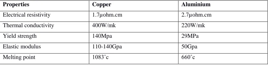
Table No:1
Comparison Table for Aluminium And Copper
Properties Copper Aluminium
Electrical resistivity 1.7µohm.cm 2.7µohm.cm
Thermal conductivity 400W/mk 220W/mk
Yield strength 140Mpa 29MPa
Elastic modulus 110-140Gpa 50Gpa
Melting point 1083˚c 660˚c
Table No:2
THERMAL PROPERTIES
S. NO. CHARACTERITICS COPPER ALUMINIUM
1 Thermal conductivity 400 w/mk 220 w/mk
2 Thermal expansion Less High
3 Radiation Less High
4 Heat transfer High Less
Table No:3
OTHER PROPERTIES
S. NO. CHARACTERITICS COPPER ALUMINIUM
1 Corrosion Less High
2 Bio fouling Yes No
3 Tensile strength 55000 lb/in2 25000 lb/in2
4 Density 100 kg/m3 30 kg/m3
5 Weight 100 lb 48lb
6 Specific resistance 10.6 w/mft 17 w/mft
900 | P a g e
8 Market price ratio 3 3
XVI..RESULT
16.1.Without copper winding
Heating coil temperature – 1500 c
Rise in temperature of block from 320 c to 800c – 30 minutes 16 sec
Drop in temperature of block from 800c to 400c – 19 minutes 28 sec.
16.2.With copper winding
Heating coil temperature – 1500c
Rise in temperature of block 320c to 800c – 42 minutes 35sec
Drop in temperature of block from 800c to 400c – 15 minutes 20sec.
XVII..CONCLUSION
The fins used in automobiles engines fins are made with aluminum alloy material. The heat dissipation of
aluminum alloy is 3.3w. The fins material is by changing of aluminum alloy addition of copper alloy the heat
dissipation of fins will be better than present exiting fins used in automobile engine. If is experimentally found
that the heat dissipation of fins made of aluminum copper alloy is 3.6w that greater the exiting fins.
REFERENCES
[1] Heat and Mass Transfer author by – “Dr.C.P.KOTHANDARAMAN”
[2] Fins – non fiction book return by “Dr.David der-weiwang