Sharif University of Technology
Scientia IranicaTransactions B: Mechanical Engineering http://scientiairanica.sharif.edu
Estimation of mixed-mode fracture parameters by gene
expression programming
A. Khademalrasoul
and A. Adib
Department of Civil Engineering, Engineering Faculty, Shahid Chamran University of Ahvaz, Ahvaz, Iran. Received 4 November 2017; received in revised form 5 August 2018; accepted 29 October 2018
KEYWORDS Fracture mechanics; Gene Expression Programming (GEP); Stress Intensity Factors (SIFs); Extended nite element method.
Abstract. The linear elastic fracture phenomenon is characterized by Stress Intensity Factors. In this study, a general function was obtained in order to predict the fracture parameters. The numerical calculation of the SIFs in a mixed-mode condition is a cumbersome task. In this research, more than 6800 numerical analyses using the extended nite element method were conducted to simulate the fracture problem. States were considered for a plate with an arbitrary edge or center crack. Mixed-mode SIFs were calculated by the interaction integral. Then, Gene Expression Programming (GEP) method was utilized to extract a function. Results showed acceptable correlations between numerical calculations and genetic programming functions. R-square (R2) values are in
the range of 0.91 to 0.96, which guarantee the accuracy of the inferred functions. © 2020 Sharif University of Technology. All rights reserved.
1. Introduction
Stress intensity factors are important parameters of the linear elastic fracture mechanics [1{3]. SIFs are useful for life prediction and fracture initiation in the structures. Further, crack path prediction is based on the concept of the SIF. Therefore, it is possible to arrest a crack according to the SIFs and the stress conditions in the vicinity of the crack tips. In general, there are three independent modes of fracture in the structural elements. Opening, shearing, and tearing are admissible displacements of crack surfaces with respect to each other. In two-dimensional problems, opening and shearing modes are considered [4]. Crack propagation could be determined with a combination of these two modes of fracture. Maximum tangential stress, minimum strain density, and maximum energy
*. Corresponding author.
E-mail addresses: [email protected] (A. Khademalrasoul); [email protected] (A. Adib) doi: 10.24200/sci.2018.5512.1319
release rate are the most important criteria in the crack propagation. However, crack path prediction is characterized by the SIFs that demonstrate the stress conditions in the vicinity of the crack tips. Therefore, many eorts have been made on dierent approaches to calculating the SIFs [5{14]. Numerical, analytical, and experimental studies have been conducted on the principles of the fracture parameters [15].
Finite element method, boundary element ap-proach, meshless methods, and isogeometric analysis are signicant numerical methods in fracture mechan-ics. Among them, the Extended Finite Element Method (XFEM) has emerged as a exible approach in the fracture mechanics framework [16{18]. Mesh-less and isogeometric analysis methods have some diculties in essential boundary conditions [19{22]. Moreover, the stiness matrix in the boundary element method is fully developed and, hence, matrix calculus is somewhat time consuming [23]. In other words, since the XFEM is based on the conventional nite element analysis, all benets of nite element method are preserved. In general, XFEM mathematically is based on the concept of the partition of unity
ap-proximation nite element spaces [24{26]. Additional degrees of freedom are introduced in the nite element approximation spaces and, eventually, any kind of discontinuities is implicitly imposed on the solution space. In this way, the inuences of the discontinuities are considered in the stress distributions.
Unlike other extensive studies on fracture param-eters, limited studies have performed on the concept of the genetic algorithm and articial neural networks to estimate the fracture parameters [27]. This may arise from the fact that these methods need a lot of input data [28,29], whereas collecting a large number of the SIFs in dierent bodies with various geometries is a cumbersome task. Direct and indirect approaches have been used to calculate the SIFs. Stress extrapolation and displacement extrapolation are direct approaches, and the energy method is indirect method [30]. In the framework of the energy methods, since the SIFs are calculated using remote data from the crack tip, higher accuracy can be achieved.
Gene Expression Programming (GEP) method states the best equation for calculating the SIF based on dierent geometries and loading conditions. GEP was rst invented by Ferreira and is a development of GP [31]. Although GEP uses the same kind of expression tree as GP, the entities evolved by ET are the expression of genomes.
In this investigation, a large number of numerical analysis cases are used to predict the fracture param-eters. In order to generate the input data, more than 6800 numerical models using the XFEM are produced. In this study, the XFEM in combination with the level set method is adopted to simulate any kind of discon-tinuous media. Two level set functions were utilized to simulate the crack tips (crack tip function) and crack body (Heaviside function). Among dierent methods for the SIF calculation, the interaction integral is used. The interaction integral (M-integral) is based on the well-known J-integral. M-integral is the dual form of the J-integral. Interaction integral is formulated in the XFEM computer code using MATLAB programming language. All numerical calculations of the M-integral implemented in the computer code are solved auto-matically. All procedures include equivalent domain selection around the crack tips, detection of the crack tip elements, and the mathematical solutions of the integrals. By applying interaction integral, both the rst and second stress intensity factors are obtained in one solution step. Then, inuencing parameters for the SIFs are chosen as the input data for genetic programming models. These parameters consist of loading conditions, geometry specications, and crack congurations. Crack congurations such as the length of the crack and the crack inclination angles are chosen. Geometry specications include the width and height of the plates. Finally, loading conditions are remote
stress acting whether in the x (shear mode) and y (tension mode). Then, genetic programming is used to predict a function for SIFs in mixed-mode conditions. However, the functions that have been proposed for the single edge-crack plate are mostly focused on the pure mode. This study considers the general mixed-mode conditions. Functions are inferred for plates with edge and center cracks with arbitrary inclinations up to 60 degrees with respect to the horizon. Quadratic nite element meshes are considered ne enough to achieve accurate results. Further, in order to increase the numerical integration in the vicinity of the crack tips, the sub triangulation is performed on the crack tip elements. Then, in order to establish the obtained functions, T -pair test is conducted. h and p values are calculated to be an approval for the GEP calculations. In addition, the Root Mean Square Error (RMSE) is chosen as the tness function.
This paper is outlined as follows: Section 2 is dedicated to explaining the principles of the XFEM. Section 3 shows the calculation of the mixed-mode SIFs in one step using the interaction integral. Section 4 explains the genetic programming method in function nding problems. Section 5 presents the numerical results by the XFEM and expresses the unique formulas for both SIFs in edge and center cracked plates. 2. Principles of the XFEM
The XFEM was rstly introduced [32]. It is charac-terized by some special features in fracture mechanics. These special features of the extended nite element result from the partition of unity nite element prop-erty of XFEM, of which the most prominent features include:
1. The ability to include the local behavior of the solution in the nite element space;
2. The ability to construct nite element spaces of any desired regularity.
The XFEM can be assumed to be a classical FEM capable of handling arbitrary discontinuities. In fact, in the XFEM, any types of discontinuities are modeled implicitly onto the solution space [33,34]. In this method, by introducing additional degrees of freedom, any kind of discontinuities can be modeled. The XFEM approximates the displacement of point x as follows:
u(x) : R2! R2;
uh(x; t) =X i2I
ui(t)Ni(x)
+X
j2J
+X
k2K
Nk(x) 4
X
l=1
al
k(t)Bl(r; )
!
; (1)
where Ni(x) is the standard basis function of the nite
element for the ith node, and t is time. Time is used for each parameter, which increases monoton-ically. Therefore, the whole solution steps include equilibrium equations with no dynamic eects. J and K represent nodal point sets for crack body and crack tip, respectively. ui, bj, and ak demonstrate
degrees of freedom. Further, H( (x; t)) and Bl(r; )
are the enrichment functions of the XFEM. These two functions are called Heaviside and crack tip enrichment functions, respectively. The enrichment functions consist of two series of functions. By introducing these functions to the inuenced nite element nodes, the implicit additional degrees of freedom are added to the solution space. On the other hand, the eects of the considered discontinuity are simulated numerically. 3. Interaction integral
Behavior of a body with a discontinuity, such as crack, is generally characterized by a parameter such as SIFs or path independent J-integral in linear elastic fracture mechanics. Further, during the last decades, much eort has been made for SIFs calculation. Theoreti-cal, numeriTheoreti-cal, and experimental methods have been employed for determining the SIFs in the vicinity of the crack tips.
Interaction integral (M-integral) has been used for mixed-mode of fracture problems. M-integral was introduced by Yau et al. [35] for isotropic materials. In fact, M-integral is the dual form of the J-integral for the cracked body. In this method, an auxiliary eld is introduced and imposed on the solution space. The auxiliary stresses and displacement derived by Westergaard and Williams have been used. Displace-ment and stress auxiliary elds have been chosen in a situation to satisfy the equilibrium equations and boundary conditions in the problem of the traction-free crack surfaces. The mixed-mode of SIFs has been calculated in one solution by conducting a computer subroutine in the extended nite element framework. This integral is numerically calculated in the equivalent area in the vicinity of the crack tips. The interaction integral is dened as follows:
M(1;2)=Z A
(1)ij @u(2)i
@x1 + (2) ij @u
(1) i
@x1 W (1;2)
1j
! @q1
@xjdA;(2)
where A is the integration area, q1 is the smoothing
function with a value of 0 or 1 for dierent nodes, ij
is the Kronecker delta, x1 is the local coordinate axis
in the crack line direction, W(1;2) is the interaction
strain energy density, ij is the stress tensor, and ui
stands for the displacements vector. It should be noted that by introducing the q1 function, the equivalent
domain around the crack tip moves like a rigid body. Superscripts \1" and \2" demonstrate the real and auxiliary elds, respectively.
4. Principles of GEP method
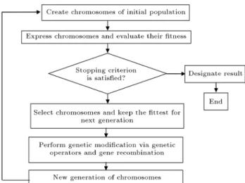
GEP was rst invented by Ferreira and is a develop-ment of GP [31]. Although GEP uses the same kind of expression tree as GP, the entities evolved by expres-sion tree are the expresexpres-sion of genomes. In basic GEP, genes (individuals) are often selected and copied into the next generation based on their tness by roulette-wheel sampling with elitism [31]. This guarantees the survival and cloning of the best individual to the next generation. The variation in the population is introduced by applying one or more genetic operators to select chromosomes. Most genetic operators used in genetic algorithms can also be implemented in GEP with minor changes, including crossover, mutation, and rotation. The owchart of GEP is shown in Figure 1. The algorithm begins with an initial population with many genes. After generations of evolution, the best chromosome will be selected and its decoding process can be expressed [31]. According to the GEP rules, the genes will be expressed as ETs and the ETs can also be easily decoded as an algebraic equation. A more detailed description of GEP can be found in the referenced study [31].
In our work, the procedure of construction for handgrip force prediction is as follows:
Step 1: Population initialization
The set of functions F and the set of terminals T were selected to create the chromosomes. The edge-crack and center-crack plates are dierent in terms of chosen elements. Five elements were chosen
Figure 2. Geometric conguration of cracked plates.
as in a mathematical function set for edge-crack problems: F = [+; ; ; ; power]. The termi-nal set (b; h; a; yy; xx) was selected. Lengths of
head and tail are 8 and 30, respectively, and ve genes per chromosomes were employed. In addi-tion, nine elements were chosen as in a mathemat-ical function set for center-crack problems: F = [+; ; ; ; power; sqrt; exp; sin; cos]. The terminal set (b; h; a; ; yy; xx) was selected. Lengths of head
and tail are 8 and 30, and six genes per chromosomes were employed. Figure 2 shows the assumed plate with an edge or a center crack;
Step 2: Genetic operation
Basic genetic operators were applied for each gen-eration including mutation, inversion, IS (Insertion Sequence) transposition, RIS (Root Insertion Se-quence) transposition, one-point recombination, two-point recombination, gene recombination, and gene transposition. The details about how these opera-tors are implemented can be seen in the referenced study [31];
Step 3: Fitness calculation
The maximum tness (fmax) was set to 1000 based on the default of GEP method and the suitable magnication of maximum tness; then, the tness was calculated as follows:
ffitness= 1000 MSE1
i+ 1; (3)
where: MSEi= m1
m
X
j=1
(Fij Tj)2:
MSE represents the mean square error, m is the total number of tness cases, Fij is the value output by
the individual program i for the tness case j (out of m tness cases), and Tj is the target value for the
tness case j. For a perfect t, Fij = Tj [31];
Step 4: Termination criterion There are two termination criteria:
1. ffitness= fmax;
2. The maximum number of generations reached 2000.
If either criterion is satised, stop; else, go to Step 2 [31].
The owchart of this research is outlined in Figure 3.
5. Results
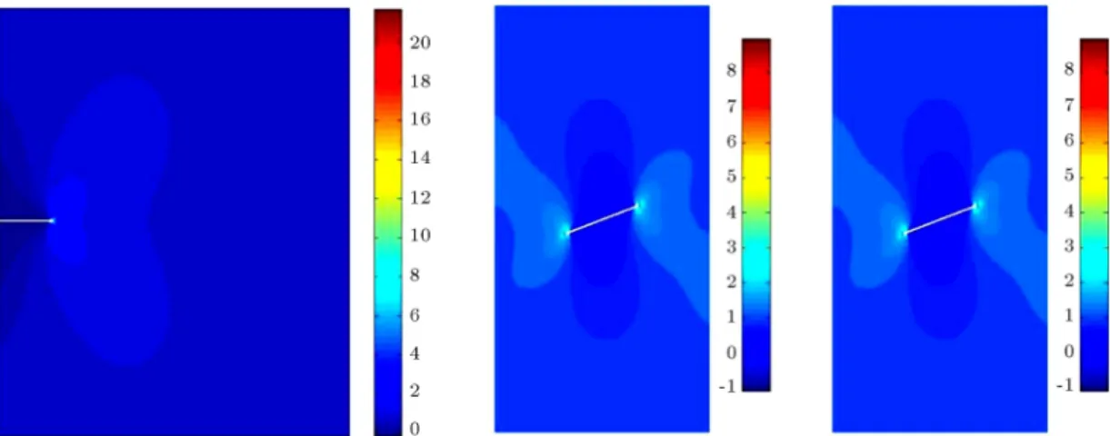
In the rst step, in order to determine the accuracy of the nite element modeling, the stress distributions for edge and center cracked plates are shown. Quadratic nite element mesh is considered ne enough to obtain an exact solution. Rectangular nite element mesh was constructed with 0:02 0:02 elements in width and height. Further, because of the importance of the numerical integration in the vicinity of the crack tips, sub-triangulation is conducted on elements, which are located in the integration area. Figure 4 demonstrates the stress distributions for cracked plates containing edge and center cracks with dierent inclinations. 5.1. SIFs calculation
This section is dedicated to making a comparison between current numerical analysis using XFEM and existing experimental-analytical solutions for evaluat-ing SIFs. Details of the numerical calculations for edge-crack plates are illustrated in Table 1.
In addition, Table 2 illustrates the computational SIFs for center-crack plates under uniaxial tension. Since previous experimentalanalytical solutions in -nite plates are mostly in pure mode, results are shown for the pure-mode problems.
5.2. The results of GEP method for edge-crack problems
GEP method states an equation for predicting mode I (KI) and mode II of fracture (KII) in edge-crack
problems based on width of domain (b), height of
Figure 4. Stress distribution for a plate containing an edge crack and center cracks. Table 1. Stress intensity factors for single edge-crack plate under uniaxial tension. Crack length
Analytical-experimental
KI
Numerical KI Numerical KII KKI(numerical)= I (analytical)
0.1 0.6296 0.6251 0.0018 0.993
0.2 0.9082 0.9135 0.0025 1.006
0.3 1.1493 1.1547 0.0032 1.005
0.4 1.3846 1.3869 0.0038 1.001
0.5 1.6266 1.6258 0.0044 0.999
0.6 1.8825 1.8789 0.0051 0.998
0.7 2.1581 2.1535 0.0058 0.998
0.8 2.4591 2.4532 0.0008 0.998
0.9 2.7927 2.7905 0.0009 0.999
1.0 3.1674 3.1708 0.001 1.001
1.5 6.1407 6.1340 0.0161 0.999
2.0 13.1032 13.4695 0.0038 1.028
Table 2. Stress intensity factors for center-crack plate under uniaxial tension. Crack length
Analytical-experimental
KI
Numerical KI Numerical KII KKI(numerical)= I (analytical)
0.1 0.3979 0.3982 0.0000 1.001
0.2 0.5648 0.5434 0.0000 1.01
0.3 0.6943 0.6787 0.0000 0.976
0.4 0.8050 0.7919 0.0000 0.984
0.5 0.9043 0.8988 0.0000 0.994
0.6 0.9963 0.9810 0.0000 0.985
0.7 1.0838 1.0701 0.0000 0.987
0.8 1.1687 1.1566 0.0000 0.990
0.9 1.2528 1.2422 0.0000 0.992
1.0 1.3375 1.3278 0.0000 0.993
1.5 1.8153 1.7940 0.0000 0.988
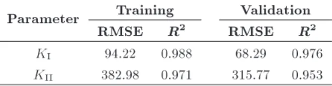
Table 3. The Root Mean Square Error (RMSE) and R2
of training and validating the developed equations by Gene Expression Programming (GEP) method for edge crack.
Parameter Training Validation
RMSE R2 RMSE R2
KI 94.22 0.988 68.29 0.976
KII 382.98 0.971 315.77 0.953
domain (h), length of crack (a), tension stress (yy),
and shear stress (xx). The number of considered
geometries and loading conditions and values is 2124 for edge-crack problems. In this research, GEP method is used from power, +, { , and / functions. The number of genes and chromosomes is 5 and 30, respectively, and the size of head is 8. Results of the numerical method (for 2124 states) were applied for the training and validation of the developed equations by GEP method (80% of data for training and 20% of data for validation).
The signicance of these equations was deter-mined by t-test. This test showed that there were signicant relations between calculated KI and KII by
the numerical models and predicted KI and KII by
GEP method. The signicant level is 1% and p-values are 0.7083 and 0.7813 for KI and KII, respectively.
Degrees of Freedom (Df) of the t-test is 4246. The values of the test statistics are 0.3742 and 0:2777 for KI and KII, respectively. In addition, the values of
standard deviation are 84.7846 and 9.7566 for KI and
KII, respectively. The RMSE and R2 of training and
validating the developed equations by GEP method are illustrated in Table 3.
The developed equations by GEP method for Mode one of fracture in edge-crack plates for the mixed mode of fracture are as follows:
G1C8 = 2:28021990608709; G1C5 = 1:28783142637904; G2C9 = 4:84246639304335; G2C1 = 4:95895260475478; G2C4 = 7:80024855522324; G3C3 = 3:20169682912687; G3C2 = 0:878299089422313; G3C1 = 1:36135438765005; G4C5 = 9:95291498316064; G5C1 = 0:772524115659732; y = 0:0;
y =(yy=(G1C8=(b
realpow(realpow(a; G1C5); G1C5)))); y =y + ((((b + b) yy) + realpow(a; G2C9))
=(realpow(h; a) + (G2C1 + G2C4))); y =y + (a ((G3C3
+ realpow(realpow(G3C1; b); G3C2)) yy));
y =y+((d(4)=(d(1)+((G4C5=d(1)) d(2))))d(3)); y =y+(arealpow((((a=b)yy)=(G5C1+b)); a));
KIpredict = y: (4)
Moreover, the developed equations by GEP method for Mode two of fracture in edge-crack plates are as follows:
G1C2 = 0:634809827115886; G1C4 = 3:24860522578786; G2C6 = 7:96888487182226; G2C5 = 7:9865730202641; G2C3 = 2:82639945239753; G2C0 = 0:579835990882018; G3C5 = 0:82648295819544; G3C7 = 7:66337909045983; G4C0 = 93:0965971274657; G4C6 = 10:8990646128312; G5C1 = 0:766952253388981; G5C2 = 3:13861613436109; y = 0:0;
y =((((xx b) xx) G1C2)
=realpow(exp(h); (G1C4 a))); y =y + ((((xx=G2C5)=(G2C3=b))
=((h + G2C0)=a)) G2C6);
y =y+((xx (((h+a)=G3C7)+(xx=h))) G3C5);
y =y + (realpow(G4C0; ((exp(yy) G4C6)
y =y+((xx=((b + G5C1)(bG5C2)))exp(a));
KIIpredict = y: (5)
5.3. The results of GEP method for center-crack problems
In this section, by conducting genetic programming principles, a unique formula is inferred from the data for an arbitrary center crack. In these problems, a cen-ter crack with any inclination angle with respect to the horizon up to 60 degrees is considered. In particular, for a plate with a center crack, there are two tips in the computational domain. The SIFs for both of the crack tips are calculated by implementing the interaction integral. The results demonstrated that the values of the SIFs were the same for two crack tips. Therefore, accordingly, the extracted GEP formula can be used for each desired crack tip. GEP method expresses an equation for the prediction of mode I (KI) and mode
II of fracture (KII) in center-crack problems based on
the width of domain (b), height of domain (h), length of crack (2a=2), crack orientation angle (), tension stress (yy), and shear stress (xx). The number of
considered dierent geometries and loading conditions is 4710 for center-crack problems. In this research, +; ; ; ; power; sqrt; exp; sin; cos mathematical func-tions are utilized for GEP solution to generate a proper formula for the prediction of both SIFs in center-crack plates. By conducting a series of diagnostic analyses, there are 6 genes and 30 chromosomes, respectively. The size of head is selected to be 8. Results of numerical simulations (for 4710 states) were applied for training and validating the developed equations by GEP method (80% of data for training and 20% of data for validation).
Eventually, the signicance of the extracted equa-tions was determined by the t-test. This test shows that there are signicant relations between the calculated KIand KII by the numerical models and the predicted
KI and KII by GEP method. Therefore, from the
implementation point of view, one can use the inferred formula instead of the numerical simulation. The signicance level is considered 1% and p-values are 0.2511 and 0.7917 for KI and KII, respectively. The
Degrees of Freedom (Df) for the t-test is 9420. The values of the test statistic are 1:1476 and 0:2641 for KI and KII, respectively. In addition, the values of
standard deviation are 6.9121 and 3.6832 for KI and
KII, respectively. The RMSE and R2 of training and
validating the developed equations by GEP method are illustrated in Table 4.
Results demonstrate inferred functional relations for estimating the fracture parameters. These results generate an accurate mixed-mode fracture initiation. Eq. (6) is obtained for KI prediction for any kind of
Table 4. The Root Mean Square Error (RMSE) and R2
of training and validating the developed equations by Gene Expression Programming (GEP) method for center crack.
Parameter Training Validation
RMSE R2 RMSE R2
KI 396.93 0.957 382.69 0.951
KII 504.81 0.928 467.14 0.909
center-crack plates:
G2C9 = 0:757119862771529; G3C9 = 4:54871208075198; G3C5 = 1:27180460798975; G3C3 = 5:29529709768975; G4C3 = 1:41314424963903; G4C2 = 3:84813610579428; G5C2 = 0:397656178472243; G5C9 = 3:15164718252734; G5C4 = 1:22101216812634; G6C7 = 0:635492167409079; y = 0:0;
y = (cos(((cos(b) (xx=h)) + cos(a))) a);
y =y + realpow((sin((a=G2C9)) + ((yy+ yy) a)); cos());
y =y + sin(exp((G3C9
(cos(realpow(G3C5; G3C3))(a + xx)))));
y =y + cos(exp((
+ realpow((exp(G4C2)=h); (G4C3 ))))); y =y + ((xx (a G5C2))
(cos(G5C9)= cos(G5C4)));
y = y + sin((a sin((h exp((G6C7 xx))))));
KIpredict = y: (6)
Further, Eq. (7) is inferred from the GEP solution to predict KII of center-crack plates. In the presented
relations, the unit of crack inclination angles, , is considered in radian.
G2C1 = 9:12337040144215; G2C0 = 8:47272255623035; G3C6 = 0:417246421040969; G3C5 = 2:90015291132003; G4C6 = 4:5951719718009; G4C3 = 544:124293487823; G5C3 = 8:96053060670797; G5C7 = 4:82549630761725; G5C5 = 7:21011415951111; y = 0:0;
y = ((cos(b sin(yy))) a) a;
y =y + sin((((a ) (yy=G2C1))
+ (yy (G2C0 b))));
y =y+((sin(sin(((G3C5) G3C6)))a)yy);
y =y + (cos(G4C6) (cos(realpow(yy; ))
sin((b G4C3))));
y =y + (realpow(exp((a=G5C5)); G5C3) =(sin(h) + G5C7));
y =y+exp((arealpow(cos(exp(sin(b))); yy)));
KIIpredict = y: (7)
The main objective of this research is to extract appropriate equations. These extracted equations can be used for determining characteristics of edge and center cracks, and it is not necessary to apply numerical models following their extraction.
6. Conclusion
In this research work, unique formulas in the mixed-mode condition were inferred from the data for pre-dicting fracture parameters. Data were generated by the numerical method. The Extended Finite Element Method (XFEM) was used to produce more than 6500 input data. In fact, by combining the interaction
integral with the XFEM, the mixed-mode Stress In-tensity Factors (SIFs) were calculated. Models consist of edge-crack plates and center-crack plates. Genetic programming was utilized to nd appropriate functions for Modes one and two of fracture parameters. R-square and correlation coecients were in a condition that demonstrated the signicant relationships between predicted and numerical SIFs. Further, in order to examine the functions, the T -test was done on the results. T -test results proved the existence of a correlation between input data and the output results. Therefore, this study used the suggested functions instead of numerical solutions to estimate the fracture initiation.
References
1. Zahnder, A.T., Fracture Mechanics, Springer (2012). 2. Gdoutos, E.E., Fracture Mechanics: An Introduction,
Springer (2005).
3. Janssen, M., Zuidema, J., and Wanhill, R., Fracture Mechanics, Second Edition, Taylor & Francis (2004). 4. Aliha, M.R.M., Behbahani, H., Fazaeli, H., and
Reza-ifar, M.H. \Experimental study on mode I fracture toughness of dierent asphalt mixtures", Scientia Iran-ica, 22(1), pp. 120{130 (2015). (en)
5. Likeb, A., Gubeljak, N., and Matvienko, Y. \Stress intensity factor and limit load solutions for new pipe-ring specimen with axial cracks", Procedia Mater. Sci., 3, pp. 1941{1946 (2014).
6. Joseph, R.P., Purbolaksono, J., Liew, H.L., Ramesh, S., and Hamdi, M. \Stress intensity factors of a corner crack emanating from a pinhole of a solid cylinder", Eng. Fract. Mech., 128, pp. 1{7 (2014).
7. Evans, R., Clarke, A., Gravina, R., Heller, M., and Stewart, R. \Improved stress intensity factors for selected congurations in cracked plates", Eng. Fract. Mech., 127, pp. 296{312 (2014).
8. Duan, J., Li, X., and Lei, Y. \A note on stress intensity factors for a crack emanating from a sharp V-notch", Eng. Fract. Mech., 90, pp. 180{187 (2012).
9. De Luycker, E., Benson, D.J., Belytschko, T., Bazilevs, Y., and Hsu, M.C. \X-FEM in isogeometric analysis for linear fracture mechanics", Int. J. Numer. Methods Eng., 87(6), pp. 541{565 (2011).
10. De Klerk, A., Visser, A.G., and Groenwold, A.A. \Lower and upper bound estimation of isotropic and orthotropic fracture mechanics problems using ele-ments with rotational degrees of freedom", Commun. Numer. Methods Eng., 24(5), pp. 335{353 (2008). 11. Yoneyama, S., Ogawa, T. and Kobayashi, Y.
\Evaluat-ing mixed-mode stress intensity factors from full-eld displacement elds obtained by optical methods", Eng. Fract. Mech., 74(9), pp. 1399{1412 (2007).
12. Banks-Sills, L., Wawrzynek, P.A., Carter, B., Ingraf-fea, A.R., and Hershkovitz, I. \Methods for calculating stress intensity factors in anisotropic materials: Part II{Arbitrary geometry", Eng. Fract. Mech., 74(8), pp. 1293{1307 (2007).
13. Ayhan, A.O. \Stress intensity factors for three-dimensional cracks in functionally graded materials using enriched nite elements", Int. J. Solids Struct., 44(25{26), pp. 8579{8599 (2007).
14. Shahani, A.R. and Nabavi, S.M. \Closed form stress intensity factors for a semi-elliptical crack in a thick-walled cylinder under thermal stress", International Journal of Fatigue, 28(8), pp. 926{933 (2006). 15. Chen, D-C., Chang, D-Y., Chen, F-H., and Kuo,
T-Y. \Application of ductile fracture criterion for tensile test of zirconium alloy 702", Scientia Iranica, 25(2), pp. 824{829 (2018). (en)
16. Khademalrasoul, A. \Linear and curvature internal heterogeneous boundaries inuences on mixed mode crack propagation using level set method", Journal of Structural and Construction Engineering, 4(3), pp. 42{ 54 (2017).
17. Sukumar, N. and Prevost, J.H. \Modeling quasi-static crack growth with the extended nite element method. Part I: Computer implementation", Int. J. Solids Struct., 40(26), pp. 7513{7537 (2003).
18. Moes, N. and Belytschko, T. \Extended nite element method for cohesive crack growth", Eng. Fract. Mech., 69(7), pp. 813{833 (2002).
19. Yin, S., Yu, T., Bui, T.Q., Liu, P., and Hirose, S. \Buckling and vibration extended isogeometric analysis of imperfect graded Reissner-Mindlin plates with internal defects using NURBS and level sets", Computers & Structures, 177, pp. 23{38 (2016). 20. Bui, T.Q. \Extended isogeometric dynamic and static
fracture analysis for cracks in piezoelectric materials using NURBS", Comput. Meth. Appl. Mech. Eng., 295, pp. 470{509 (2015).
21. Bhardwaj, G., Singh, I.V., Mishra, B.K., and Kumar, V. \Numerical simulations of cracked plate using XIGA under dierent loads and boundary conditions", Mech. Adv. Mater. Struct., 23(6), pp. 704{714 (2016). 22. Bhardwaj, G., Singh, I.V., and Mishra, B.K. \Stochas-tic fatigue crack growth simulation of interfacial crack in bi-layered FGMs using XIGA", Comput. Meth. Appl. Mech. Eng., 284, pp. 186{229 (2015).
23. Arzani, H., Kaveh, A., and Taheri Taromsari, M. \Optimum two-dimensional crack modeling in dis-crete least-squares meshless method by charged system search algorithm", Scientia Iranica, 24(1), pp. 143{152 (2017).
24. Sukumar, N., Huang, Z.Y., Prevost, J.H., and Suo, Z. \Partition of unity enrichment for bimaterial interface cracks", Int. J. Numer. Methods Eng., 59(8), pp. 1075{ 1102 (2004).
25. Moes, N., Dolbow, J., and Belytschko, T. \A nite element method for crack growth without remeshing", Int. J. Numer. Methods Eng., 46(1), pp. 131{150 (1999).
26. Babuska, I. and Zhang, Z. \The partition of unity method for the elastically supported beam", Comput. Meth. Appl. Mech. Eng., 152(1{2), pp. 1{18 (1998). 27. Nasiri, S., Khosravani, M.R., and Weinberg, K.
\Frac-ture mechanics and mechanical fault detection by articial intelligence methods: A review", Eng. Fail. Anal., 81(Supplement C), pp. 270{293 (2017). 28. Greenbaum, J., Wu, K., Zhang, L., Shen, H., Zhang,
J., and Deng, H-W. \Increased detection of genetic loci associated with risk predictors of osteoporotic fracture using a pleiotropic cFDR method", Bone. 99(Supplement C), pp. 62{68 (2017).
29. Xue, Y., Cheng, L., Mou, J., and Zhao, W. \A new fracture prediction method by combining genetic algorithm with neural network in low-permeability reservoirs", Journal of Petroleum Science and Engi-neering, 121(Supplement C), pp. 159{166 (2014). 30. Mohammadi, S., Extended Finite Element Method: for
Fracture Analysis of Structures, Wiley (2008). 31. Ferreira, C., Gene Expression Programming:
Mathe-matical Modeling by an Articial Intelligence, Springer (2006).
32. Belytschko, T. and Black, T. \Elastic crack growth in nite elements with minimal remeshing", Int. J. Numer. Methods Eng., 45(5), pp. 601{620 (1999). 33. Babuska, I. and Melenk, J. \The partition of unity
method", Int. J. Numer. Methods Eng., 40, pp. 727{ 758 (1997).
34. Melenk, J.M. and Babuska, I. \The partition of unity nite element method: Basic theory and applications", Comput. Meth. Appl. Mech. Eng., 139(1{4), pp. 289{ 314 (1996).
35. Yau, J.F., Wang, S.S., and Corten, H.T. \A mixed-mode crack analysis of isotropic solids using conserva-tion laws of elasticity", Journal of Applied Mechanics-Transactions of the ASME, 47(2), pp. 335{341 (1980).
Biographies
Abdolghafour Khademalrasoul is an Assistant Professor at the Civil Engineering Department, Fac-ulty of Engineering, Shahid Chamran University of Ahvaz, Ahvaz, Iran. He received BSc degree in Civil Engineering in 2006 as the top student and MSc degree in Geotechnical Engineering from Shahid Chamran University of Ahvaz in 2009. His profession includes numerical methods and computational mod-els. Moreover, he received PhD degree in Geotechnical
Engineering on the subject of computational fracture mechanics and the application and innovative notion in isogeometric analysis in 2015 from Shahroud University of Technology, Shahroud, Iran.
Arash Adib is a Professor at the Civil Engineering Department, Faculty of Engineering, Shahid Chamran University of Ahvaz. He received BSc degree in Civil
Engineering from Shiraz University in 1997 and MSc degree in Hydraulic Structures from Shiraz University in 1999. Further, he received PhD degree in Water Engineering from K.N. Toosi University of Technology in 2006. Dr. Adib was a supervisor to four PhD students and almost 30 MSc students. He published more than 50 journal papers and 100 conferences papers.