Experience of using a haptic interface to follow a robot
without visual feedback
GHOSH, Ayan, PENDERS, Jacques <http://orcid.org/0000-0002-6049-508X>,
JONES, Peter <http://orcid.org/0000-0002-1225-0192> and REED, Heath
<http://orcid.org/0000-0003-2615-3315>
Available from Sheffield Hallam University Research Archive (SHURA) at:
http://shura.shu.ac.uk/9516/
This document is the author deposited version. You are advised to consult the
publisher's version if you wish to cite from it.
Published version
GHOSH, Ayan, PENDERS, Jacques, JONES, Peter and REED, Heath (2014).
Experience of using a haptic interface to follow a robot without visual feedback. In:
Proceedings of the 23rd IEEE International Symposium on Robot and Human
Interactive Communication. Edinburgh, 25-29 August. IEEE, 329-334.
Copyright and re-use policy
See
http://shura.shu.ac.uk/information.html
Sheffield Hallam University Research Archive
Experience of using a Haptic Interface to follow a Robot without Visual
Feedback
*Ayan Ghosh, Jacques Penders, Peter E Jones, and Heath Reed, Sheffield Hallam University
Abstract— Search and rescue operations are often undertaken in smoke filled and noisy environments in which rescue teams must rely on haptic feedback for navigation and safe exit. In this paper, we discuss designing and evaluating a haptic interface to enable a human being to follow a robot through an environment with no-visibility. We first discuss the considerations that have led to our current interface design. The second part of the paper describes our testing procedure and the results of our first tests. Based on these results we discuss future improvements of our design.
Keywords - human robot interaction; haptic interface; support for no-visibility/visually impaired
I. INTRODUCTION
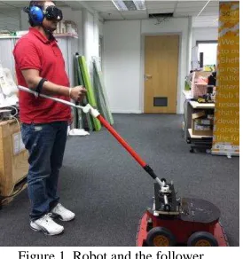
In this paper, we discuss designing an interface to enable a human being to follow a robot (as shown in Figure 1) in an environment with no-visibility. Being guided along an unknown path without visual feedback poses several challenges to a human being, in particular if the guide is a robot. A vital requirement for successful human-robot cooperation in such circumstances is that the human trusts and has confidence in the robot. Trust and confidence are complex matters, which we have explored in more detail in [14]. In this paper we focus on designing interfaces and first attempts to evaluate them.
A. No-visibility
Search and rescue operations in fire incidents, are undertaken only when the ground is relatively passable [13]; the major problem however is that the environment is smoke-filled and noisy. Rescue teams have to rely on haptic feedback for exploration and navigation. However, because of the lack of visual (and auditory) feedback, humans get easily disorientated and may get lost. Robots with a range of sensors on board might be helpful for such conditions. In addition, there are also everyday situations where vision and audition are problematic, for instance, a visually impaired person trying to navigate a busy street. Though robots are very promising, the issue of being guided by a robot is largely open and has not received much attention yet.
*Research was supported by the UK Engineering and Physical Sciences Research Council (EPSRC) grant no. EP/I028765/1.
Ayan Ghosh is a PhD student in Scentro, Sheffield Hallam University, Sheffield; email:[email protected].
Jacques Penders is a Professor at Sheffield Hallam University and deputy director of Scentro, Sheffield; email:[email protected]
Peter E Jones is a Principal Lecturer of Communication Studies, Sheffield Hallam University, Sheffield; email: [email protected]
Heath Reed is a principal designer at Art & Design Research Center, Sheffield Hallam University, Sheffield; email: [email protected]
Young et al. [18] describe walking a robot using a dog-leash. They note that leading a robot consists of a delicate interplay between the human leader and the robot, requiring ongoing communication and interaction. This includes (for both the robot and the human) monitoring the other’s movement direction and speed [18]. The dog-leash is used in conditions of good visibility and a relatively low level of environmental noise.
[image:2.612.373.510.256.402.2]
Figure 1, Robot and the follower.
However, lacking visual and aural feedback hampers orientation and causes significant stress, for rescue workers as well as for the visually impaired. This lack of feedback constitutes a significant obstacle when aiming to cater for trust and confidence. Nevertheless, Bremner and Cowle [1] note: the senses touch, proprioception, vision, and occasionally audition, ‘convey information about the environment and body in different neural codes and reference frames’. Research has also highlighted the extraordinary speed and sensitivity of the haptic sense [8]. This provides enough ground to explore how to make better use of the haptic sense. Eventually, a well-designed haptic interface suitable for guidance in no-visibility conditions might also be useful in everyday conditions and may free the visual sense and related mental resources so that they can be used for other tasks.
B. Navigation and following
en-route decision points) the guide dog provides locomotion guidance between these decision points; refer to Figure 2. Locomotion guidance is effected through a simple haptic interface between dog and handler - that is a rigid handle held by handler and attached to the dog's harness.
Figure 2, Handling a guide dog/robot; task analysis[14]
The current paper has the focus on locomotion guidance or simply following a robot in a safe manner. By simplifying the task, we are able to take the first steps towards evaluating the subject's performance and experience, while following the robot.
The paper is organised as follows: after a brief literature (Section II) review, we discuss in Section III, the design presumptions and considerations, which led to the implementation of the final interface (shown in Figure 1). In Section IV, we describe our preliminary test trials. We finish with a discussion of further implications of the study and issues to be resolved in future work.
II. LITERATURE OVERVIEW
In the literature reports about the experience of human subjects with human-robot interaction in low-visibility is rather sparse. The Guardians project [13] pioneered a group of autonomous mobile robots assisting a human rescue worker operating within close range. Trials were held with fire fighters and it became clear that the subjects by no means were prepared to give up their procedural routine and the feel of security provided: they simply ignored instructions that contradicted their routines.
There are several works on robotic assistance to the visual impaired. Tachi et al. [16] developed a guide-dog robot for the visually impaired, which leads the person. The robot tracks the follower using active sonar, and the follower wears a stereo headset, which provides coded aural feedback to notify whether the follower is straying from the path. There is no means to communicate to the robot, and the follower must learn the new aural-feedback code: the robot serves as a mobile beacon that communicates with the headset.
Allan Melvin et al., [12] developed a robot to replace a guide dog; however the paper does not extensively report trials with users. The GuideCane [17] is a cane like device running on unpowered wheels, it uses Ultra Sound to detect obstacles. The follower has to push the GuideCane - it has no powered wheels- however it has a steering mechanism that can be operated by the follower or operate autonomously. In autonomous mode, when detecting an
obstacle the wheels are steering away to avoid the obstacle. The GuideCane has been tested with 10 subjects three of whom were blind and cane users, the other seven were
sighted but blindfolded. Basic conclusion: ‘walking with the
GuideCane was very intuitive and required little conscious
effort’, unfortunately nothing more is reported on the
subjects' experience.
The robotic shopping trolley developed by Kulyukin [4][11] is also aimed at the visual impaired. This trolley guides the (blind) shopper - who is holding the trolley handle - along the aisles into the vicinity of the desired product. The locomotion guidance is fully robot driven but restricted to navigating the aisles; the emphasis is on instructing the shopper how to grab the product using voice instructions.
III. ROBOTIC GUIDE
A. Path
Our first step towards making a robot guide a human is to build an interface by means of which the follower can be guided along a safe path. The safest path for the follower is a path that the robot already has traversed; hence our experiments, reported below, look at the movements and behaviour of the follower in terms of the ability to closely match the live path of the robot.
B. Knowing where the leader is
Obviously, in order to be able to follow the robot, the follower needs to know where the robot is, relative to his/her current position and orientation. Initially our project looked at three distinct interfaces: a wirelessly connected device for instance a Nintendo Wii, a short rope/rein or leash and a stiff handle. A major problem for any wireless device lies in how to indicate the position of the robot with respect to the follower. A rope does indicate the direction of the robot but only when there is no slack. Young et al. [18] use a spring-loaded retractable leash design (popular with dogs), which keeps the leash taut; the retracting mechanism however obscures the length of the leash and thus the distance between the robot and the follower is not known. Our final choice has been for a stiff handle, which directly indicates the position (direction and distance) of the robot.
C. Interaction with a Stiff interface:
that a crutch like design of the handle, in which the stick is fixed on the lower arm, is preferred.
Figure 3, Hand held stick with ball free mechanism on a disc with omni-directional wheels
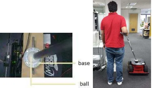
[image:4.612.71.287.94.147.2]D. Implementing the handle (stiff Rein) on the robot We implemented a simple crutch-like handle prototype. The joint at the base -connecting the stick to the robot- consisted of a ball-free mechanism (as shown in Figure 4, Left). This mechanism allows full freedom in the horizontal plane as well as some limited freedom in the vertical direction. First trials revealed that with the ball free mechanism the follower lost track of the orientation (heading) of the robot, though its position was clear. As a consequence, the follower was not safe following the robot when the robot was passing a slightly protruding object as illustrated in (Figure 4, Right).
Figure 4, Left, Ball-free mechanism at the base; Right, Unsafe, non-matching path
These findings led to the design of a third prototype. This prototype consists of a mechanical spring system at the base, as presented in Figure 5, which replaces the previously used ball free mechanism while retaining the freedom in the vertical direction. The spring system allows rotation of the handle in the horizontal direction. When the spring system has zero tension, the handle is aligned with the center line of the robot. When the handle is being rotated, the spring system induces tension on the handle, which increases with the rotation angle. The system also comes with a pin enabling to nullify the action of the springs. With this 'pin on', the handle is, in the horizontal plane, rigidly fixed to the robot. Thus, the handle provides two testing options: 1. The handle is attached in a fixed joint (rigid): meaning the handle is fixed at base using the pin.
2. The handle is attached with a flexible joint (spring): meaning the handle can rotate in the horizontal plane, and rotation induces tension on the handle.
Figure 5, Handle with spring system
E. Robot and sensors
The handle has been mounted on a Pioneer-3AT 4-wheel robot. In the experiments reported below, the robot was autonomously navigating fixed trajectories while being supervised by an operator, who was able to stop or start the robot remotely [9]. The overall aim of the study is to evaluate the use of an autonomous robot guide. However, autonomous behaviour can occur in many variants; for our study, we confined the robot to five pre-programmed repeatable behaviours. Thus the robot was made to move autonomously in one of the following pre-programmed trajectories:
path A: Straight line (≈ 5 meters) + longer right turn (≈
1.5 meters) + straight line (≈ 3 meters).
path B: Straight line (≈ 5 meters) + gentle right turn (≈ 1
meters)+ straight line (≈ 3 meters).
path C: Straight line (≈ 5 meters) + longer left turn (≈
1.5 meters)+ straight line (≈ 3 meters).
path D: Straight line (≈ 5 meters) + gentle left turn(≈ 1
meters) + straight line (≈ 3 meters).
When the robot moves in a straight line, the set linear speed is inspired by the normal walking speed of a person. However, for setting the robot's angular speed we do not have an intuition; therefore we designed a shorter turn (close to 45 degrees) and a longer turn (close to 70 degrees). On straight lines, the robot operated with a linear speed of 0.6m/s; in the turns linear speed was also 0.6m/s and the angular speed was set at 0.5 rad/s resulting into a circle arch with a radius of about 1.25 m.
[image:4.612.55.298.322.463.2]15-20 cm left of the center line of the robot. In the reconstruction the position of the robot and the feet of the person were marked in each frame. These points were connected using a spline function, the result of which was projected on all frames (refer to Figure 9-Figure 11). Measurements in the frames have been based on rough calibrations in the frame using the known size of the robot and distances between the floor markers.
IV. PRELIMINARY EVALUATION
As reported above, our handle has been redesigned following very informal preliminary trials, the latest design is shown in Figure 5. Believing this design is relatively stable, we set out to define and carry out more formally structured trials. The primary evaluation purpose was to test usability of the robot as a guide and whether a person could comfortable and safely follow the robot. In an attempt to define a numerical criterion, we observed how closely the path of the follower matches the live path of the robot. A.
Testing Protocol
We studied the effect of two different settings of the stiff interface on the following behaviour of right-handed participants. On each of the trials, the subjects were asked to use the stiff handle in one of the following modes: 1. The handle attached in a fixed joint (rigid) 2. The handle attached with a flexible joint (spring)
[image:5.612.314.558.301.366.2]Based on our findings in a set informal trials on these paths, reported in [19], we followed up with a second set more formalised trials.
Figure 6, Picture used in pictorial assessment technique for spatial awareness
Six subjects took part in our experiment. Each subject was asked to undergo two sessions with four trials in each session (using, in random order, either the rigid or the spring handle setting on -in random order- the paths A-D described above). At the start of the first session, the subjects were instructed on how to perform the task and were asked to sign a consent form. Subjects were blindfolded and asked to put headphones on. Before the commencement of each trial, the handle was attached to the subject's forearm and a gentle pat was the pre-arranged haptic signal from the experimenter, used to indicate the start of each trial. In order to make the subjects familiar with the experimental
environment before the commencement of the first session, the subjects were given a trial run on which, they were asked to follow the robot moving in a straight-line for 8 meters (approximately) blindfolded.
Questionnaires were administered after every trial while the next trial was set up. A five-point SAM scale [20] was used in an attempt to understand the experiences of the subject with respect to confidence, calmness and comfort. We also used a non-verbal pictorial assessment technique to understand the subject's sense of spatial awareness. The subjects were asked to report which path they believed to have followed choosing, as far as possible, one of the options shown inFigure 6, where
A = straight line; B = straight line plus sharp right turn; C = straight line plus sharp left turn; D = straight line plus gentle right turn; E = straight line plus gentle left turn; F = straight line plus semi-circular path plus straight line G = gentle right turn plus straight line
[image:5.612.79.278.424.544.2]H = straight line plus a very acute left turn
Figure 7, Mean confidence (left), comfort (middle) and calmness (right) for six subjects across trials as per SAM scale
B. Experimental results
Non-Verbal Emotional Responses:
Fire fighters should feel confident with equipment. Figure 7, shows the emotional states of the subjects on confidence, comfort and calmness (measured via 5-point SAM scale). The figures provide a very rough indication of the range of subjective reactions to the experimental environment and the task, with subject 3 scoring consistently at the higher end and with subject 4 scoring at the lower end.
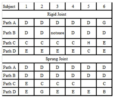
[image:5.612.342.529.511.672.2]Sense of Spatial Awareness:
Spatial awareness is very important for fire fighters. Figure 8 shows subjects' responses on their senses of spatial awareness. Every option (one out of eight refer to Figure 6) chosen after each trial, was noted against the relevant path followed. As is evident from the table, the subjects were mostly accurate in determining whether the turn was a left or right turn, however they were less accurate in distinguishing between the gentle and longer turns, right turns - whether long (path A) or short (path B) - were nearly all experienced as the same, left turns show more diversity. Does the Follower's path match that of the robot;
[image:6.612.316.558.107.217.2]The paths reconstructed on the videos frames, in the figures 9-11 using video analysis software, may contain some error, nevertheless overall patterns can be recognised. Observing the experiments, it became clear that there is an acute difference in the following behaviour when the robot is turning right refer to Figure 9 and Figure 10 and when the robot is turning left refer to Figure 11, summarised in Figure 12.
Figure 9, Subject 3 (left) and 4 (right) longer turn to the right with fixed handle setting
On right turns, the follower's path deviates considerably more from the path of the robot with subject 3 (scoring on the higher ends concerning confidence etc) reaching a maximum of 0.44 deviation and subject 4 (lower confidence score) maximum 0.47 m. In the left turns the maxima reduce to 0.18m for subject 3 and 0.36m for subject 4.
[image:6.612.56.297.326.445.2]In the right turns, deviations start very abrupt, but remain smaller with the sprung-joint. In the turns the follower is exerting some force on the robot and this causes the robot to slip and maybe slide, the distances but also the angles of the turns are not exact as Figure 12 shows.
Figure 10, Subject 3 (left) and 4 (right) longer turn to the right with flexible handle setting
Turning left:
[image:6.612.322.551.394.545.2]Figure 11, Subject 4 longer turn to the left with fixed (left) and flexible (right) handle settings respectively
Figure 13, gives the mean time delays (t in seconds) for four subjects with different handle settings. t is the delay between the point in time when the robot starts to turn and the time when the follower starts to turn. While the fixed setting of the handle alerts the follower of the movements of the robot more immediately, thereby resulting in abrupt tugs in the turns, the flexible handle setting allows for a build-up of tension within the spring mechanism, meaning that the forces on the subject accumulate gradually, thereby causing a delay between the start of the robot's turn and the follower reacting to it. That delay makes for a smoother turn and one that is spatially more accurate.
Subje ct 3 angle deviat ion angle deviat ion
Path A(l onge r ri ght) 67 0.44 68 0.29
Path B(shorte r ri ght) 43 0.37 48 0.09
Path C (l onge r l e ft) 69 0.18 -
-Path D(shorte r l e ft) 48 0.1 55 0
Subje ct 4 angle deviat ion angle deviat ion
Path A(l onge r ri ght) 70 0.38 70 0.32
Path B(shorte r ri ght) 45 0.47 46 0.27
Path C (l onge r l e ft) 74 0.32 78 0.18
Path D(shorte r l e ft) 53 0.36 55 0.28
Rigid Joint Sprung Joint
Rigid Joint Sprung Joint
Figure 12, Table representing angle of turn (degrees) and deviation (meters) from the path of the robot, for four subjects (two different handle
settings)
V. DISCUSSION
The findings of the experimental trials raise a number of issues about the design of the handle and user experience that deserve further investigation. First of all, it seems clear that when the handle is attached with a flexible joint (spring) the follower's path better matches the path of the robot; there is only little displacement of the human follower from the robot's trail.
[image:6.612.55.297.600.697.2]delivered by the inflexible handle may give the handler a keener awareness of spatial orientation and location. But in terms of subject experience, the SAM-scale revealed no significant differences in how subjects responded to different handle settings, although they did show that different subjects have quite different overall reactions to the trial context.
[image:7.612.73.276.166.295.2]
Figure 13, Mean T (time delays in seconds) for four subjects with fixed/sprung handle settings.
Future experiments will have to compare right and left handed subjects in order to confirm our intuition that on a left turn a left handed person is also forced to step out and mirrors the pattern of a right turn by a right handed person. A complicating factor is the slippage caused by the forces the follower exerts on the robot, applying a much heavier robot may give more reliable measurements for Figure 12. However this may come with a cost in terms of subjects' experience, refer to Figure 7. Future work will concentrate on refining the objective and subjective measures of path correspondence and examine to what extent following can be seen as a learnable skill, with the handle becoming 'transparent technology' and helping in 'human-technology symbiosis' [10].
VI. CONCLUSION
In this paper, we have presented a haptic interface attached to an autonomous robot for locomotion guidance. We have reported on a small scale experimental study of different settings of the interface. Our trial data show a) that the handle interface with spring mechanism affords a more effective solution to the 'matching path' problem, although this conclusion needs to be qualified in the light of our observations about the interactional nature of the path., b) that subjects have different subjective responses to the experimental setting but not to different handle settings, c) subjects show accurate spatial awareness in relation to gross orientational parameters (left versus right) but whether
they are capable of more fine-grained assessments of direction and orientation is unclear.
REFERENCES
[1] A. J. Bremner, and D. Cowie, "Developmental Origins of the Hand in the Mind," and "The Role of the Hand in the Development of the Mind" (in [15], 2013).
[2] A. Clark, "Natural Born Cyborgs:Mind,Technologies and The future of Human Intelligence," Oxford: Oxford Univ. Press, 2003.
[3] A Clark, "Supersizing the Mind: Embodiment, Action, and Cognitive Extension," Oxford: Oxford University Press, 2011.
[4] C. P. Gharpure, and V. A. Kulyukin, "Robot-assisted shopping for the blind: issues in spatial cognition and product selection," Intelligent Service Robotics, 2008, Volume 1, Number 3, 237-251, DOI: 10.1007/s11370-008-0020-9.
[5] R.G. Golledge, R. L. Klatzky, and J. M. Loomis, "Cognitive mapping and wayfinding by adults without vision," in J Portugali (ed.) The Construction of Cognitive Maps, Kluwer Academic Publishers: 215-246, 1996.
[6] R Harris, "Signs, Language and Communication," London: Routledge, 1996.
[7] R Harris, "The integrational conception of the sign", in Integrationist Notes and Papers 2006-2008, Sandy:Bright Pen, 61-81, 2009.
[8] M. A. Heller, W. Schiff, and L. Erlbaum, "The Psychology of Touch," Inc. 1991.
[9] A. Janani, A. Holloway, H. Reed, and J. Penders, "Design of a Mechanical Impedance Filter for Remote Haptic Feedback in Low-Visibility Environment," TAROS, 2013.
[10] P. Jones, A. Ghosh, J. Penders, and H. Read, "Towards human technology symbiosis in the haptic mode,".In: International Conference on Communication, Media, Technology and Design, Famagusta, North Cyprus, 2-4 May 2013. 307-312, 2013.
[11] V. Kulyukin and A. Kutiyanawala, "Accessible shopping systems for blind and visually impaired individuals: Design requirements and the state of the art," The Open Rehabilitation Journal, 2010.
[12] A. Melvin, A. Prabu, B. Nagarajan, R. Bukhari, and Illia, "ROVI: a robot for visually impaired for collision- free navigation," Proceedings of the International Conference on Man-Machine Systems (ICoMMS 2009). [13] J. Penders, L. Alboul, U. Witkowski, A. Naghsh, J. Saez-Pons, S. Herrechtsmeier, and M. El-Habbal, "A robot swarm assisting a human firefighter," Advanced Robotics, 25:93-117, 2011.
[14] J. Penders, P. Jones, A. Ranasinghe, and T. Nanayakara, "Enhancing trust and confidence in human robot interaction," In: UKRE, Sheffield, 25-3-2013.
[15] Z. Radman, "The Hand, an Organ of the Mind," MIT Press, 2013.
[16] S. Tachi, R. W. Mann, and D. Rowell, “Quantitative comparison of alternative soensory displays for mobility aids for the blind,” IEEE Trans.
Biomedical Engineering, vol. 30, no. 9, pp. 571–577, Sep. 1983.
[17] I. Ulrich, and J. Borenstein, "The GuideCane-applying mobile robot technologies to assist the visually impaired," Systems, Man and Cybernetics, Part A: Systems and Humans, IEEE Transactions on Issue Date: Mar 2001 Volume: 31, Issue:2 On page(s): 131 - 136 ISSN: 1083-4427.
[18] J. E.Young, Y. Kamiyama, J. Reichenbach, T. Igarashi, and E. Sharlin, "How to Walk a Robot: A Dog-Leash Human-Robot Interface," In: International Symposium on Robot and Human Interactive Communication, RO-MAN, pp. 376–382 (2011).
[19] A. Ghosh, J. Penders, P. Jones and L. Alboul,"Following a Robot using a Haptic Interface without Visual Feedback." ACHI2014 (in press). [20] J .D. Morris, "SAM: the Self-Assessment Manikin", J of Adv
![Figure 2, Handling a guide dog/robot; task analysis[14]](https://thumb-us.123doks.com/thumbv2/123dok_us/736211.578287/3.612.65.277.145.219/figure-handling-a-guide-dog-robot-task-analysis.webp)