Abstract—Multiuser multi-input multi-output (MU-MIMO)
system has been widely used in 4G communication system. MU-MIMO has high data rate and improved capacity, however, it has multiuser interference (MUI) and multiple access interference (MAI). Block diagonalization (BD) is one of the methods to solve MUI and MAI, which uses precoding algorithm to separate each user in the system. A generalized zero-forcing channel inversion (GZI) algorithm is the simplest precoding method to improve BD. However, the BD/GZI algorithms use uniform power distribution. The water-filling technology performs power allocation based on channel environment of each user. In this paper, the BD/GZI algorithms are combined with water-filling technology to perform power allocation and MUI/MAI cancellation for the MU-MIMO systems. The proposed algorithms are with space-frequency water-filling. Some simulation examples are given to demonstrate the effectiveness of the proposed algorithm.
Index Terms—block diagonalization, water-filling, optimal
power allocation, multiuser multi-input multi-output.
I. INTRODUCTION
HE new generation of wireless communication systems is providing multimedia services that require very high data rates. The high spectral efficiency can be achieved by using multiple antennas at both the transmitter and receiver, so multiple-input multiple-output (MIMO) systems have gained popularity due to their capability in delivering high spectral efficiency and their robust performance against fading. MIMO communication technologies have recently received much interest due to the promising capacity gain when employing multiple transmit and receive antennas. Information theoretic results show that MIMO systems can offer significant capacity gains over traditional single-input single-output systems. This capacity increase is enabled by the fact that the signals from each individual transmitter appear highly uncorrelated at each of the receive antennas in rich scattering wireless environments. The receiver can exploit these differences in spatial signatures to separate the signals originated from different transmit antennas. In multipath channel, the received signal in a MIMO receiver is corrupted by the inter-symbol interference (ISI), spatial interference, and co-antenna interference (CAI). Single-user MIMO (SU-MIMO) considers only the dimensions of multiple antennas for a single mobile device. However,
The authors are with the Department of Electrical Engineering, National Chung-Hsing University, Taiwan (e-mail: [email protected]; [email protected]; [email protected]).
2Ye-Shun Shen is with the National Formosa University (e-mail:
multiuser MIMO (MU-MIMO) can deploy multiple users as spatially distributed transmission resources at the cost of more complex signal processing, and is also known as spatial division multiple access (SDMA). Thus, multiuser MIMO considers the overall capacity of network when several users are accessing the same link simultaneously. Due to transmission array gain, diversity gain, spatial multiplexing gain and interference cancellation gain, MIMO techniques can increase system throughput and transmission reliability without increasing the required bandwidth that makes MIMO communication technologies become one of the most promising ways for wireless communication by dirty paper coding (DPC) [1-13]. The purpose of DPC is to pre-cancel interference at the transmitter using know full channel state information (CSI). Block diagonalization (BD) is one of the well-known precoding algorithms near DPC techniques [4-5]. A generalized zero-forcing channel inversion (GZI) algorithm is the simplest precoding method to improve BD.
Water-filling technique has been proposed by [8] and has been used in MIMO system that uses each antenna CSI to find maximum eigenvalue to do power allocation as the spatial domain water filling. In [5, 7, 9, 17], the spatial domain water-filling with BD algorithm is employed in multiuser MIMO system to find maximum sum capacity. The frequency domain water-filling technique has been proposed by [13, 14] that the time-domain signal is transferred to frequency domain and then each subcarrier is water- filling processed. In this paper, the BD/GZI algorithms are combined with both spatial-domain and frequency-domain water-filling technologies to perform power allocation and MUI/MAI cancellation for the MU-MIMO systems. The rest of this paper is organized as follows. In Section 2, the BD precoding algorithm and GZI precoding algorithm for MU-MIMO downlink system is described. The proposed spatial-frequency water-filling algorithm is described in Section 3. Simulation results and conclusions are provided in Section 4 and Section 5, respectively.
Notation: Vectors and matrices are denoted by boldface letters; superscripts of
*,
T,
H, and
1 denote the complex conjugate, transpose, Hermitian transpose, and inverse, respectively; stands for the Kronecker product; and diag{} denotes a diagonal matrix; IK is the KK identity matrix; E{}denotes the statistical expectation.II. BLOCK DIAGONALIZATION FOR MULTIUSER MIMO
SYSTEM
A. Block Diagonalization
The multiuser MIMO downlink system with K
On Space-Frequency Water-Filling Precoding
for Multi-User MIMO Communications
Yu-Kuan Chang, Ye-Shun Shen2, Fang-Biau Ueng and Shao-Hua Tsai
independent users can be shown as Figure 1. The transmitted signal goes through precoding matrix and then received with receiver filter to decode the desired user signal. Block diagonalization (BD) is the well-known precoding method for the system [1-5]. Define the transmitted symbol vector x, noise w and the precoding matrix P as follows,
K
T T K T
T
T T K T
T
P P
P P
w w
w w
x x
x x
... ... ...
2 1
2 1
2 1
(1)
The received signal can be described as
y y y
HPx wy T K
T
T ...
2
1 (2)
where His the channel information matrix and can be
defined as
TK
TT
T H H
H
H 1 2 ...
The received signal can be rewritten as follows,
w x P H x P H
y
K
j k k
k k j j j j
, 1
(3) Define the received filter M for all users as follows,
K
diag M M M
M 1 2 ... (4) The desired output signal xˆj can be shown as
w M x P H M x P H M
x j
K
j k k
k k j j j j j j
j
1,
ˆ (5)
The key idea of the BD is to design the precoding matrix that satisfies the following condition,
0 , 1 ,
j j j k j kK
H P (6)
So Pj should be in the null space of Hj ~
that is defined as follows,
T
TK T
j T
j T
j H H H H
H~ 1 ... 1 1 ... (7)
The SVD of Hj ~
can be described as
Hj j j j j
) 0 ( ) 1
( ~
~ ~ ~
~ U Λ V V
H (8)
where Uj ~
and Λj ~
denote the left singular vector matrix and the matrix of ordered singular values of Hj
~
, respectively. The matrix V~(j1) and
) 0 ( ~
j
V denote the right singular matrices each consists of the singular vectors corresponding to nonzero singular values of Hj
~
and zero singular values of j
H~ . The desired user has non-interfering block channel )
0 ( ~
j jV
H . In order to decouple this block channel into nj parallel sub channels, the SVD of HjV~(j0) is computed as
bHj b j b j H j j j j j
j j j j j
j Λ V U Λ V
U V
H ~(0) HV~(0) HV~(0) HV~(0)
SVD (9)
Employing Pj V~(j0)V(jb) and
H b j j
) ( U
M in (5), the desired user’s signal vector xˆ can be shown as follows, j
j H b j j b j
j Λ x U w
xˆ ( ) ()
(10) Finally, we can find the precoding matrix P as follows,
() (0) ( )
2 ) 0 ( 2 ) ( 1 ) 0 ( 1
~ ... ~
~ b
K K b
b V V V V
V V
P (11)
The all user’s received filter can be described as follows,
bH
K H
b H b
diagU1( ) U(2) ... U( )
M (12)
B. Generalized Zero-Forcing Channel Inversion
For the so-called Generalized Zero-Forcing Channel Inversion (GZI) method [5], we need to perform the pseudo-inverse operation of the channel matrix Hi as follows,
K
H i i H i
i H HH H H H
Hˆ ˆ ˆ ... ˆ 2 1 1
(13)
Consider the QR decomposition of matrix Hˆ j with dimension Ntnj as follows,
j j j Q R
Hˆ ˆ ˆ for j1,...,K (14) where Rˆ j is an njnj upper triangular matrix and Qˆ j is an Ntnj matrix whose columns form an orthonormal basis for Hˆ j . In (13), due to ˆ 0
~ j jH
H , we have
0 ˆ ˆ ~
j j jQ R
H . Since Rˆ j is invertible, it follows that 0
ˆ ~
j jQ
H . As in the BD algorithm, in order to decouple this block channel into parallel sub channels, the SVD of HjQˆ j is computed as follows,
vpHj vp j vp j H j j j j j
j j j j j
j Λ V U Λ V
U Q
H ˆ HQˆ HQˆ HQˆ
SVD (15)
Employing Pj Qˆ jV(jvp) and
H vp j j
) (
U
M in (5), the desired user’s signal vector xˆj can be described as follows,
j H vp j j b j
j Λ x U w
xˆ ( ) ( )
(16) Finally, we can find the precoding matrix P as follows,
( ) ( )
2 2 ) ( 1
1 ˆ ... ˆ
ˆ vp
K K vp
vp Q V Q V
V Q
P (17)
The all user’s received filter can be shown as
vpH
K H
vp H vp
diagU1( ) U(2 ) ... U( )
M (18)
For the BD and GZI algorithms, we assume that transmitter knows the channel station information perfectly. However, due to the mismatch between the transmitter and receiver, the transmitter can not accurately know CSI. Define
err
H as the channel estimation error, the CSI can be described as follows,
err est H
H
H (19)
where H and Hest are the true CSI and the estimated CSI, respectively. We assume that Herr is uncorrelated with
est
H and x. Herr has i.i.d. elements with zero mean and estimation error variance e2,h. So the received signal in (2) can be rewritten as
s s s err s s est
s H Px H Px w
y (20)
where the HerrPsxs is the estimation error term, and we define the total error term is eHerrPsxsws. The total error variance e2 can be shown as follows,
2
2, 2
2 Tr
w r s H s h e t
e N N
e P P (21)
For the BD algorithm, equation (7) can be rewritten as
T
TK est T
j est T
j est T
est
j ,1 ... , 1 , 1 ... ,
~ H H H H
H (22)
est est estK
H i est i est H i est iest ,1 ,2 ,
1 , , ,
, ˆ ˆ ... ˆ
ˆ H H H H H H
H (23)
III. THE PROPOSED WATER-FILLING ALGORITHM A. Spatial-Domain Water-Filling
Please check with your editor on whether to submit your manuscript as hard copy or electronically for review. If hard copy, submit photocopies such that only one column appears per page. This will give your referees plenty of room to write comments. Send the number of copies specified by your editor (typically four). If submitted electronically, find out if your editor prefers submissions on disk or as e-mail attachments.
Consider the system shown as in Figure 3, the capacity for complex AWGN MIMO channel when H is perfectly known at the receiver can be expressed as follows [7, 8],
max ( ) ( ; ) log det * 2 n a x p fixedH H Q H I Y X I C (24)
The capacity under ergodicity conditions when H is perfectly known at the receiver can be described as
log det * 2
n a H ergodic H Q H I E C (25)
where n2 is the noise covariance,
*2 ( ) ( )
l j k i n En t n t
.
The transmitter correlation matrix Q can be diagonalised as *
V D V
Q Q
0 0 0 0 0 0 0 T Q P D (26)
We can obtain the result that the capacity is the sum of the capacity of the parallel channels, that is
) , min( 1 2 2 ) ( 2 * * ) ( * * ) ( _ 1 log det log N M i n j b j a n b j Q b j a H fixed U V V D V V U I C Φ Λ Λ Λ (27)The sum rate RBD for the BD algorithm can be written in terms of the following maximization [5,6],
total K j j K j w j b j BD P R j
1 1 2 2 ) ( 2 ) Tr( subject to det log max Φ Φ Λ I Φ (28)The optimal power loading matrix Φj can be calculated from the sum rate (28) by using the water-filling method [9-12], 2 ) ( 2 b j n j Λ
Φ with μ such that T
K
j
j P
1Φ (29)
Using (23) and (25), the optimal capacity can then be
described as
) ( 2 such that 2 2 ) ( log b j n j n b j a C Λ Λ (30)Finally, we can find the block diagonalization precoding matrix PBD as
21 ) ( ) 0 ( ) ( 2 ) 0 ( 2 ) ( 1 ) 0 ( 1 ~ ... ~ ~ Φ V V V V V V P b K K b b
BD (31)
The all user’s received filter can be shown as
bH
K H b H b BD
diagU1() U(2) ... U( )
M (32)
Similarly, the GZI precoding matrix PGZI is as follows,
21 ) ( ) ( 2 2 ) ( 1
1 ˆ ... ˆ
ˆ V Q V Q V Φ
Q P vp K K vp vp
GZI (33)
The all user’s received filter is
vpH
K H
vp H vp
GZI diag ( ) ( )
2 ) (
1 U ... U
U
M (34)
B. Spatial-Frequency Domain Water-Filling
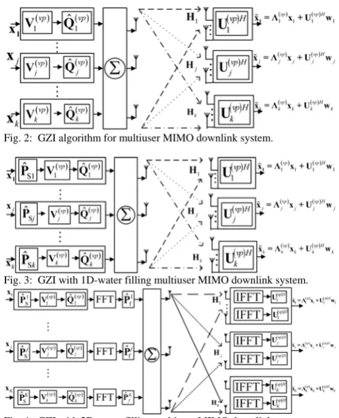
The multiuser MIMO downlink system with space-frequency domain water filling can be shown as Fig. 4. The transmitted signal goes through precoding matrix and water filling and then received with receiver filter to decode the desired user’s signal. If the GZI method is employed to perform space- domain water filling, the signal before FFT operation can be described as follows,
T
K vp K vp K SK vp vp S vp vp S K S S S S x V Q P x V Q P x V Q P x x x x ) ( ) ( 2 ) ( 2 ) ( 2 2 1 ) ( 1 ) ( 1 1 2 1 ˆ ... ˆ ˆ ... (35) Then after N-point FFT operation, the frequency-domain signal of the jth user is as follows,
j
vp j vp j Sj T T N T T
j X X X FP Q V x
X ( ) ( )
2
1 ... ˆ
(36)
Collecting the all user signal we obtain
TK vp K vp K SK T vp vp S T T K T T x V Q P F x V Q P F X X X X ) ( ) ( 1 ) ( 1 ) ( 1 1 2 1 ˆ ... ˆ ... (37)
Let N be the number of subcarrier, fi be the i -th sub-channel, P[i] be the transmitted power of the i -th subchannel. The capacity of the k-th subchannel is given[14,15],
0 2 2 ] [ ] [ 1 log N k P k H f fC k (38)
Where f , H[k], P[k] and N0 denote the subcarrier spacing, frequency response, transmission power and noise variance of the k-th subchannel. The total channel capacity is given by the sum of the capacity for individual subcarriers,
1 0 N k k f C C (39)
NP k P N k P k H f C used N N N k N k P P N k k P P
1 0 1 0 0 2 2 ,..., 1 0 ,..., ] [ subject to ] [ ] [ 1 log max max 1 0 1 0 (40)where P is the average power for each subcarrier available in the transmitter. Employing the Lagrange multiplier method for optimization with equality constraint in Equation (40), the following solution is obtained. We can find the optimum solution by maximizing the Lagrange function defined by [16],
NP k P N k P k H L used N k N k 1 0 1 0 0 22 [ ]
] [ ] [ 1
log (41)
That is (42)
0 ] [ ] [ ] [ 1 log ] [ ] [ 1 0 1 0 0 2 2
P N k P N k P k H k P k PL Nused
k N k 0 ] [ 1 0
NP k P L Nusedk (43) 0 ] [ ] [ 1 1 0 2 N k P k H
The solution is
otherwise 0 0 ] [ 1 if , ] [ ] [ ] [ 1 ] [ 2 0 2 0 2 0 2 0 * k H N k H N k H N k H N k
P
(44)
where is the Lagrange multiplier that is chosen to meet the power constraint in Equation (44).
Each frequency-domain user signal is then multiplied frequency-domain water-filling operation and can be express as follows,
T K K vp K vp K SK fK T vp vp S f T T K T T f x V Q P F P x V Q P F P X X X X ) ( ) ( 1 1 ) ( 1 ) ( 1 1 1 2 1 ˆ ... ˆ ... (45) The total transmit signal can be described as
T
Nt K T K T T Nt T T X X X X X X S S S S ... ... ... ... 2 1 1 2 1 2 1 (46)
IV. SIMULATION RESULTS
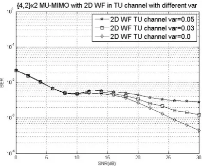
In this section, we provide some simulation examples to demonstrate the performance of the proposed method. The results will be verified by Monte Carlo simulation method, and the adopted channel model is the COST 207 RA/TU/BU environments. We compare the BER performance of our proposed algorithm with that without water-filling. The simulated modulated signal format is QPSK. The simulated number of active users is K=2. For the TU channel model, the number of paths L is equal to 12. For the BU channel model, the number of paths L is equal to 21. For the simulations, two precoding algorithms, BD and GZI algorithms, are employed to combined with spatial-domain and frequency-domain water-filling technology for the MU-MIMO system. For the MU- MIMO system, the base station is equipped with four antennas and the mobile station is equipped with two antennas.
In Fig. 5, we compare the bit error rate (BER)
performances of the MU-MIMO systems with and without BD algorithm, an further compare the BER performances with 1-D (spatial-domain) water-filling and 2-D (spatial-domain and frequency-domain) water-filling. Fig. 5 shows that the proposed 2-D water-filling BD algorithm has superior performance compared with 1-D BD algorithm and conventional BD algorithm. In Figs. 6-7, we show the performance degradation of the conventional BD/GZI precoding algorithms and the water-filling BD/GZI algorithm in the situation of channel mismatch, respectively. The proposed water-filling BD/GZI algorithm outperforms the conventional BD/GZI algorithm, especially in the low signal-to-noise ratio condition. In Figs. 8-9, we compare the BER performances of the GZI algorithm with and without water-filling technology in COST-207 TU and BU channels, respectively. Figs. 8-9 show that 2-D water-filling GZI precoding algorithm outperforms 1-D or conventional GZI, even though the transmission power is one half of that of conventional GZI. In Figs. 10-11, we show the performance degradation of the proposed 2-D water-filling GZI precoding algorithms in the situation of channel mismatch in COST-207 TU and BU channels, respectively. The proposed 2-D water-filling GZI algorithm has BER 0.001 at SNR 15 dB even though channel mismatch exists.
V. CONCLUSION
The water-filling technology performs power allocation based on channel environment of each user and has been used in MIMO system that uses each antenna CSI to find maximum eigenvalue to do power allocation as the spatial domain water filling. In this paper, the BD/GZI algorithms are combined with water-filling technology to perform power allocation and MUI/MAI cancellation for the MU-MIMO systems. The proposed algorithms are with space-frequency water-filling. Some simulation examples are given to demonstrate the effectiveness of the proposed algorithm.
REFERENCES
[1] H. Jafarkhani, “SPACE-TIME CODING: THEORY AND PRACTICE”, Cambridge university press, 2005.
[2] K.-J. Lee, H. Sung, and I. Lee, “Linear Precoder Designs for Cognitive Radio Multiuser MIMO Downlink Systems,” in Proc. of IEEE Conference Communications, June 2011.
[3] S. Bose, D. Zhu and B. Natarajan, “Multiuser MIMO Capacity with Limited Feedback Trellis Exploration Based Precoder,” in Proc.
International Conference on Computing, Networking and Communications, Jan. 2012.
[4] J. Zhang, Y. Wu, S. Zhou and J. Wang, “Joint linear transmitter and receiver design for the downlink of multiuser MIMO systems,” IEEE Communications Letters, Vol. 9, no. 11, pp. 991-993, Nov. 2005. [5] S. S. Shim, J. S. Kwak, R. W. Heath and J. G. Andrews, “Block
diagonalization for multi-user MIMO with other-cell interference,”
IEEE Transcations on Wireless Communications, Vol. 7. no. 7, pp. 2671-2681, July 2008.
[6] H. Sung, S.-R. Lee and I. Lee, “Generalized channel inversion methods for multiuser MIMO systems,” IEEE Transactions on Communications,
Vol. 57, no. 11, pp. 3489-3499, Nov. 2009.
[7] P. He, L. Zhao, S. Zhou and Z. Niu, “Water-Filling: A Geometric Approach and its Application to Solve Generalized Radio Resource
Allocation Problems,” IEEE Transactions on Wireless
Communications, Vol. 12, No. 7, pp. 3637-3647, July 2013.
[9] P. Patcharamaneepakorn, A. Doufexi and S. M. D. Armour, “Weighted Sum Capacity Maximization Using a Modified Leakage-Based Transmit Filter Design,” IEEE Transactions on Vehicular Technology, Vol. 62, No. 3, pp. 1177-1188, March 2013.
[10] H. Li, X. Yuan, X. Lin and L. Ping, "On Water-Filling Precoding for Coded Single-Carrier Systems," IEEE Communications Letters, Vol. 13, No. 1, pp. 34-36, January 2009.
[11] Y. R. Zheng, M. Wang, W. Zeng and C. Xiao, "Practical linear precoder design for finite alphabet multiple-input multiple-output orthogonal frequency division multiplexing with experiment validation," IET Communications, pp. 836-847, August 2013.
[12] B. Enzo and B. Mauro, “A water-filling based approach for power allocation for multiple-antenna Rayleigh flat fading systems with partially coherent detection,” in Proc. of IEEE Vehicular Technology Conference, 2002.
[13] N. Jindal, W. Rhee, S. Vishwanath and S. A. Jafar, “Sum power iterative water-filling for multi-antenna Gaussian broadcast channels,”
IEEE Transactions on Information Theory, Vol. 51, no. 4, pp. 1570-1580, April 2005.
[14] Y.-H. Hu and G.-S. Kuo, “Space-Time-Frequency Domain Water-Filling in MIMO-OFDM Fading System,” in Proc. of IEEE Vehicular Technology Conference, April 2007.
[15] Y. S. Cho, J. Kim, W. Y. Yang and C. G. Kang, “MIMO-OFDM wireless communications with Matlab,” John Wiley & Sons, Ltd, 2010. [16] X. Chen, L. Zhang, L. Song, Y. Zhao and B. Jiao, "Feedback
Compression for Time-Correlated MIMO Block-Fading Channels Using Huffman Coding," in proc. IEEE International Conference on Communication Technology, pp. 411-415, Sept. 2011.
[image:5.595.44.291.8.799.2][17] L. Zhao, Y. Wang and C. Pascal, “Efficient Power Allocation Strategy in Multiuser MIMO Broadcast Channels,” in proc. IEEE International Personal Indoor and Mobile Radio Communications, pp. 2591-2595, Sept. 2013.
Fig. 1: Block diagonalization algorithm for multiuser MIMO downlink system.
Fig. 2: GZI algorithm for multiuser MIMO downlink system.
[image:5.595.320.528.53.222.2]Fig. 3: GZI with 1D-water filling multiuser MIMO downlink system.
Fig. 4: GZI with 2D-water filling multiuser MIMO downlink system.
[image:5.595.319.527.271.440.2]Fig. 5: BER performance comparisons of the proposed 2D water-filling algorithm and some existing algorithms: 4 transmit antenna, 2 receive antenna, 2 users.
Fig. 6: BER performance comparisons of the BD/GZI algorithms (without water-filling) with channel mismatch: 4 transmit antenna, 2 receive antenna, 2 users.
[image:5.595.44.292.470.775.2] [image:5.595.317.527.487.657.2]Fig. 8: BER performance comparisons of the proposed GZI water-filling algorithm with different power: 4 transmit antenna, 2 receive antenna, 2 users and TU channel.
Fig. 9: BER performance comparisons of the proposed GZI water-filling algorithm with different power: 4 transmit antenna, 2 receive antenna, 2 users and BU channel.
[image:6.595.60.271.267.441.2]Fig. 10: BER performance comparisons of the proposed GZI 2D water-filling algorithm with channel mismatch: 4 transmit antenna, 2 receive antenna, 2 users and TU channel.
[image:6.595.62.270.486.657.2]