Abstract—Testing represents a crucial phase in the development of a software system, often requiring considerable effort and resources. Our purpose is to offer a novel approach for generating test cases, based on requirements specification. We make use of scenarios used in the requirements specification phase, taking into consideration the various relationships that can exist between scenarios.
Index Terms—software development, requirements specification, testing
I. INTRODUCTION
The software development process is a lengthy and intricate process, covering several different phases. Whereas many different software processes have been defined over the years, four fundamental activities can be commonly defined for most processes: specification, design & implementation, validation and evolution [1]. The purpose of software validation is to show that a system “conforms to its specification and that it meets the expectations of the system customer” [1]. The main validation technique is represented by program testing, which is a very time consuming activity. Testing plays a vital role in deciding the delivery of the product, as well as ensuring the quality of the product [2].
Despite the fact that testing can only pinpoint the presence of errors, not their absence, as Djikstra famously stated more than four decades ago [3], testing has a crucial role in the software development process. In order to be able to perform this task, the tester needs to generate test cases, ideally making sure that all requirements have been individually checked [4].
Through various kinds of research, many different ways of dealing with test generation have been proposed over the years, like path-oriented [5], goal-oriented [6] or intelligent approaches [7]. A different kind of classification refers to three types of testing: code-based, specification-based and model based. While the most common one may be the code-based (with testing performed at the coding stage), model-based testing (often taking place at the design phase) is also gaining increasing popularity. We are mostly concerned with generating test cases based on specifications and this paper presents our approach. As stated by Shanti et. al in [8], generating test cases from specifications presents “the added advantage of allowing test cases to be available early
Manuscript received July 23, 2016; revised August 10, 2016.
Simona Vasilache is with the University of Tsukuba, Graduate School of Systems and Information Engineering (e-mail: [email protected])
in the software development cycle, thereby making test planning more effective”.
The remainder of our paper is organized as follows. Section 2 presents an overview of our proposed approach. Section 3 focuses on sequence diagrams and dependency diagrams as they are used for requirements analysis, whereas section 4 discusses the normalization process. In section 5 we explain the process of generating primary and secondary test cases. Section 6 contains related work; concluding remarks and possible future research directions are presented in section 7.
II. OVERVIEW OF PROPOSED APPROACH
We propose a method of generating test cases based on requirements specifications. According to Ian Sommerville, use-case based testing represents an effective system testing approach, because it focuses on interactions [1].
We start from sequence diagrams, as representation of scenarios, derived from use cases. After expressing each diagram using a scenario matrix, we propose the process of normalizing the sequence diagrams. Next, we use dependency diagrams (previously introduced in [10]), to show relationships between scenarios, along with dependency formulas. Finally, the test case generation takes place: using path traversal through sequence diagrams, “primary” test cases will be generated. Similarly, “secondary” test cases will be generated by traversing paths through dependency diagrams.
We develop high-level test cases, not (low-level) unit testing; we are mostly concerned with generating tests from requirements. We focus on functional requirements and through testing we make sure that all functional requirements are fulfilled. An overview of our proposed approach is illustrated in Fig. 1.
III. SEQUENCE DIAGRAMS AND DEPENDENCY DIAGRAMS IN REQUIREMENTS SPECIFICATIONS
A. Sequence diagrams
The first major step in developing an application is finding out what the system should do, reflecting the needs
of the end user (the “customer”) for the system that serves a certain purpose [1]. The process of finding out, analyzing and documenting these needs is called requirements engineering [1].
Specification-Based Test Case Generation
Using Dependency Diagrams
Simona Vasilache,
Member, IAENGFig. 1 Overview of proposed approach
The requirements of a software system are usually classified into two main categories: functional requirements and non-functional requirements. Functional requirements state explicitly what the system should do, the kind of services it should provide, how it should react to certain inputs, how it should behave in given situations and sometimes even what the system should not do [1]. Non-functional requirements refer to constraints which usually apply to the whole system, like time or organizational constraints, security, performance, efficiency etc. While it is not always easy to separate the two types of requirements, we are mostly concerned with the functional requirements. Requirements specifications is “the process of writing down the user and system requirements in a requirements document” [1]. Requirements elicitation and analysis involves software engineers working together with the system end user. Natural language is often used to elicit requirements, usually supplemented by numerous types of notations. Use cases are widely used for particularly
capturing functional requirements. They describe who does what with the system, for what purpose, without dealing with system internals. A complete set of use cases specifies all the different ways to use the system, and therefore defines all that is required of the system, from a high-level view.
One scenario represents an instance of a use case, and
shows a single path through the use case. Thus, one may construct a scenario for the main flow through the use case, and other scenarios for each possible variation of flow through the use case. Several different scenarios are possible for a single use case. The Unified Modeling
Language (UML) provides a graphical means of representing scenarios using sequence diagrams [11]. One
sequence diagram typically represents a single use case scenario or flow of events. Sequence diagrams are often used for both analysis and design purposes, as they show the interactions between objects in the sequential order that those interactions occur.
Throughout our paper we will consider the example of a simple Automated Teller Machine (ATM) system. Let us start by focusing on the following scenario: the user approaches an ATM machine and is shown the main display; (s)he inserts an ATM card into the ATM machine; after the card has been authenticated with the bank, the main options menu is displayed. Fig. 2 illustrates the corresponding sequence diagram for the above scenario.
As we defined in [12], a sequence diagram is a structure (O, M, <), where:
- O is the set of all objects appearing in the sequence diagram;
- M is the set of all messages exchanged between objects; - < shows a partial ordering of the messages.
M is the set of messages, and each message is a tuple (Mijk, N, W [,G]), where:
- Mijk is the kth message originating in object i and going to object j;
- N is the name attached to the message;
- W is the type of message; W∈{0, 1, 2} (0: simple message, 1: synchronous message, 2: asynchronous message);
[image:2.595.316.545.424.556.2]- G is the guard attached to the message
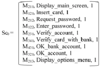
Fig. 2 Simple sequence diagram for an ATM For a given scenario, a scenario matrix is an ordered list of all message tuples (Mijk, N, W [,G]) belonging to the scenario. Fig. 3 shows the scenario matrix corresponding to the sequence diagram in Fig. 2.
[image:2.595.320.490.643.756.2]B. Dependency diagrams
Whereas one scenario represents a single “story” of the use of a system, numerous scenarios are needed for the complete description of the requirements specification of the system. When capturing the requirements, all the possible scenarios must be included.
As observed and developed in [10], these scenarios are not independent of each other, but several relationships and dependencies interconnect them. For instance, in the ATM system example, if we consider one scenario for creating a card with a bank, and another scenario for using the card for ATM operations, one of the system requirements is that the scenario of creating the card must precede the one of performing ATM operations. This illustrates a simple relationship of one scenario succeeding another (“succession”, as defined in [10]).
We have previously introduced dependency diagrams in order to represent the relationships between scenarios; our work in [10] details the notation used, as well as the types of relationships that can exist between various scenarios.
After eliciting all scenarios illustrating the requirements (represented as sequence diagrams), we need to clearly define the relationship between them. These relationships will be illustrated through a series of dependency diagrams, along with a dependency formula for each of them.
In the following, we will illustrate some possible relationships applicable to the ATM system. Let us consider 3 different scenarios as follows: one for withdrawing cash (named Scenario_withdraw), one for depositing cash (named Scenario_deposit) and one for performing a cash transfer into a different account (named Scenario_transfer). At a given time, as the user approaches the ATM, either one of these scenarios is possible. (For instance, the user cannot withdraw cash and deposit cash at the same time.) We say that these three scenarios are related through a “disjunction” relationship [10].
The dependency formula for this simple example looks like in the following:
(Scenario_withdraw ∨ Scenario_deposit ∨ Scenario_transfer)
IV. NORMALIZATION
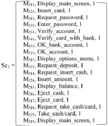
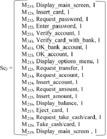
[image:3.595.312.530.51.266.2]If we analyze the above example, we can make some important observations. Before proceeding, let us express the scenario matrices for each of the three scenarios mentioned in the previous section (we will simplify the notation and call them Sc1, Sc2 and Sc3); they are represented in Fig. 4a, 4b and 4c, respectively.
Fig. 4a Scenario matrix for withdrawal
Sc1 is the scenario for withdrawing cash; Sc2 is the scenario for depositing cash, while Sc3 is the scenario for transferring cash. We can observe that the three scenario matrices have a number of common messages. They represent the part where the main screen is displayed, the user inserts the card and this card is successfully verified with the bank.
[image:3.595.353.532.414.624.2]Fig. 4c Scenario matrix for transfer
In particular, if we intend to use these scenario matrices further, for representing various relationships, it is redundant to express the set of 9 consecutive identical messages for each scenario. In order to be able to express the relationships between various scenarios/sequence diagrams in an unambiguous manner, we believe it is essential to maintain the property of having distinct, individual sequence diagrams. We believe it is important to remove the overlapping, so that we obtain disjoint sequence
diagrams, i.e. individual, distinct sequence diagrams. We call this process normalization of scenarios.
Through the process of normalization, we can isolate the identical messages and create a new scenario made up of these messages; this is the scenario that corresponds to the sequence of messages exchanged between the involved objects at the start of the transaction (whichever that is, among the three possible transactions).
The scenario matrix for our new scenario is in actual fact the scenario matrix appearing in Fig. 3 (Sc0).
Through the process of normalization, in our simple ATM example, we obtained four distinct, disjoint scenarios.
The relationships between them can be described using natural language as follows. First, the initial scenario takes place, in which the user approaches the ATM, inserts his card and the card is validated by the bank. This scenario is followed by one of the following three scenarios: scenario of withdrawing cash, scenario of depositing cash or scenario of transferring cash. The first scenario precedes any of the other three; only one of the other three scenarios can take place at a given time.
We can represent the new dependency formula as follows:
Sc0 ; (Sc1∨ Sc2∨ Sc3) ,
where Sc0 is the initial scenario and Sc1, Sc2 and Sc3 represent the withdraw, deposit and transfer scenarios, respectively (succession is denoted by “;”, whereas disjunction is denoted by “∨”).
To further our example, we can imagine two more scenarios: one in which the user changes his/her password and one of videotaping. We assume that the system is created in such a way that whenever a password is being changed, the operation is being videotaped. This creates a “conjunction” type of relationship between the two scenarios (denoted using “∧”), which can be expressed as follows:
Sc4 ∧Sc5,
where Sc4 represents the change password scenario and Sc5 represents the videotaping scenario.
V. PRIMARY AND SECONDARY TEST CASE GENERATION After the process of representing the requirements as scenarios, along with expressing the relationship between these scenarios, is completed, we can proceed to generating test cases.
When it comes to test case generation, we follow two different directions. First, we generate so-called “primary” test cases, from the individual scenarios. We achieve this by traversing paths through each sequence diagram. The scenario matrices are used as basis to generate the testing paths. This is a straightforward process: one primary test case will be generated for each sequence diagram. (The description of the algorithm for defining the path is currently at the stage of work in progress.)
Ensuring the correctness according to the primary test cases relieves some of the burden of the tester for larger system testing. This is equivalent to starting with small steps, testing “primary” behaviour first, and only afterwards addressing more complex behaviour.
After primary tests are generated, we advance towards generating the secondary tests. They are generated not from the initial (“primary”) requirements specifications, represented as scenarios, but from the enhanced requirements specifications that we proposed, which reflect the relationships between scenarios (thus the use of “secondary”). The secondary tests are generated by traversing paths in the dependency diagrams, with the information in the scenario matrices.
In our ATM example, primary testing includes four different test cases. The first one corresponds to making sure that the requirement illustrated in Sc0, i.e. checking the card with the bank as the initial step in any ATM transaction, is fulfilled. In the other tests we check whether the withdrawal transaction works according to the requirements expressed in Sc1; we do the same for Sc2 and Sc3, in order to test the functionalities of depositing cash and transferring cash.
three transactions (withdrawal, deposit or transfer) successfully. The fact that each individual (“primary”, as we named it) scenario is error free is not a guarantee that, when combined with another scenario, the system will be error free, as well. While we cannot perform an exhaustive testing, we can bring the developer one step closer to identifying as many errors as possible in the program, by testing increasingly complex behaviour.
Our future work will describe in detail both processes: that of primary test case generation, as well as that of secondary test case generation.
VI. RELATED WORK
There is a wide variety of research dealing with test case generation, either specification-based or model-based. Pahwa and Solanki offer a review of UML based test case generation methods [13]. Among the methods included in their work, the research of M. Sarma et al. is presented [14]. The authors offer an approach of generating test cases from UML design diagrams. They propose use case diagram graphs and sequence diagram graphs, integrated to form a System Testing Graph; this graph is traversed to generate test cases.
Shanti and Kumar propose test case generation by means of UML sequence diagrams using genetic algorithms, offering the best test case path [9]. Liu and Huang propose a process and a set of rules for conflict analysis in class diagrams, which can reinforce requirements analysis tasks [15]. In [16], a framework for the automated generation of use case diagrams is proposed. By developing use case diagrams and activity diagrams, functional test cases are generated. Olajubu et.al [17] present work on automating
the generation of test cases from software requirement models. They represent requirements using a modeling notation and automatically generate test cases using model to text transformation techniques.
The work presented in [20] offers an overview of research in automatic test case generation, considering 5 techniques: symbolic execution and program structural coverage testing, model-based test case generation, combinatorial testing, adaptive random testing and search-based testing.
While many research papers propose test case generation from specifications, including from sequence diagrams/scenarios, the novelty brought by our work is that scenarios as representation of requirements are not considered in isolation, but in relation to other scenarios. This is where our newly introduced dependency diagrams come into place, by reflecting these relationships.
VII. CONCLUSIONS AND FUTURE WORK
Our paper proposed a method of generating test cases from information contained in scenarios as representation of requirements, along with information included in dependency diagrams, which show relationships between various scenarios. Through our approach we allowed the
creation of more complex test cases, ensuring that a larger proportion of requirements are actually tested.
We are in the process of defining a formal description for generating primary test cases from the scenario matrices, as well as secondary test cases from the dependency diagrams. Furthermore, as future work, we intend to integrate our approach in a full system and provide a framework that allows semi-automatic test case generation.
REFERENCES
[1] Ian Sommerville, "Software Engineering", Pearson, 10th edition, 2015. [2] Priya, S. Shanmuga, and PD Sheba Kezia Malarchelvi. "Test Path Generation Using Uml Sequence Diagram", International Journal of Advanced Research in Computer Science and Software Engineering Vol. 3, No. 4, 2013.
[3] E. W. Dijkstra, “Notes on structured programming”, T.H. – Report 70-WSK-03, 1970.
[4] G. J. Myers, "The Art of Software Testing", Wiley & Sons, 2004. [5] J. Zhang, X. Chen, X. Wang, “Path-oriented test data generation using
symbolic execution and constraint solving techniques”, Proceedings of the Second International Conference on Software Engineering and Formal Methods, SEFM, 2004.
[6] B. Korel, “Dynamic method for software test data generation”, Software Testing, Verification and Reliability, Vol. 2, Issue.4, 1992, pp. 203–213
[7] K.-H.Chang, J. H. Cross II, W. H. Carlisle, D. B. Brown, "A framework for intelligent test data generation", Journal of Intelligent and Robotic Systems, April 1992, Volume 5, Issue 2, pp 147-165. [8] Shanthi A. V. K and Mohan Kumar G., “Automated Test Cases
Generation from UML Sequence Diagram”, 2012 International Conference on Software and Computer Applications (ICSCA 2012), IPCSIT vol. 41 (2012).
[9] Tripathy, A. and Mitra A., "Test case generation using activity diagram and sequence diagram." In Proceedings of International Conference on Advances in Computing, Springer India, pp. 121-129, 2013.
[10] S. Vasilache, "Dynamic Modeling in the Design Phase Using Dependency Diagrams", PhD Thesis, University of Tsukuba, 2007. [11] Unified Modeling Language™ (UML®), Retrieved from
http://www.omg.org/spec/UML/.
[12] S. Vasilache and J. Tanaka, "Support in the Software Development Process Using Dependency Diagrams", International Journal of Computer & Information Science, Vol.11, No.2, pp. 11-26, 2010. [13] Pahwa N., Solanki K., “UML based Test Case Generation Methods: A
Review”, International Journal of Computer Applications, Vol. 95, No.20, June 2014.
[14] Sarma, M. and Mall, R., “Automatic test case generation from UML models”, 10th International Conference on Information Technology, pp. 196-201, 2007.
[15] Liu C.L., Huang H.H., “Ontology-Based Requirement Conflicts Analysis in Class Diagrams”, Proceedings of the World Congress on Engineering, Vol.1, 2015.
[16] Singh, A. and Sharma, E.S., “Functional Test Cases Generation Based on Automated Generated Use Case Diagram”,International Journal of Innovative Research in Advanced Engineering (IJIRAE), Issue 8, Vol. 2, 2015.
[17] Olajubu, O., Ajit, S., Johnson, M., Turner, S., Thomson, S. and Edwards, M., “Automated test case generation from domain specific models of high-level requirements”, Proceedings of the 2015 Conference on research in adaptive and convergent systems, pp. 505-508, ACM, 2015.
[18] Vu, T.D., Hung, P.N. and Nguyen, V.H., “A Method for Automated Test Data Generation from Sequence Diagrams and Object Constraint Language”, Proceedings of the Sixth International Symposium on Information and Communication Technology, pp. 335-341, 2015. [19] Oluwagbemi, O. and Asmuni, H., “Automatic generation of test cases
from activity diagrams for UML based testing (UBT)”, Jurnal Teknologi, 77(13), 2015.