2018 International Conference on Applied Mechanics, Mathematics, Modeling and Simulation (AMMMS 2018) ISBN: 978-1-60595-589-6
Development of Reading System for Digital Display Lever Meter
Wireless Communication
Ying SONG, Shuang CHENG and Guang-bo JI
Beijing Precision Engineering Institute for Aircraft Industry, ChinaKeywords: Measured data, Analysis, Reading system, Inspection form.
Abstract. Aiming at the measurement data output mode of digital Lever meter and the principle of electrical interface, the software and hardware of wireless transmission measurement data based on Bluetooth module are developed. The measurement is guided by the two-dimensional drawings of existing CAPP system and the information of PDF process file parsing and testing procedure. A PC reading system is developed by C# language and database. The preservation of measurement data and the generation of Word test forms.
Introduction
The measurement and quality control system based on the Internet of Things is a necessary condition to realize the networking, automation and intellectualization of manufacturing industry. Its rapid development and application show the importance and urgency of networked intelligent precision measurement technology and measuring instruments in the process of transformation and upgrading of China's manufacturing industry[1]. With the rapid development of the national large-scale equipment manufacturing industry, digital lever gauge is widely used as the main tool in the assembly field. Wireless communication data acquisition of digital lever meter is a key problem in the process of quality inspection in precision machinery manufacturing industry. The purpose of this paper is to develop a wireless communication reading system for digital lever meter. Combining with Capp process specification, the corresponding test characteristics are analyzed[2,3]. The data output interface of digital lever meter is reformed to transmit wireless measurement data. The operator logs on the software and clicks on the measurement interface. Automatically from the digital lever table into the corresponding position of the measurement interface, automatically save into the database, and can generate a word version of the inspection form. It must be solved in the process of system development. The correct solution will directly affect the efficient collection and traceability of inspection data.
The main advantages of developing digital display lever table wireless communication system are as follows:
1. The lever table is small in size and high in accuracy. It is generally used for measuring the inner wall and small holes of parts. Leverage meter uses wireless communication to transmit data, increases the flexibility of traditional displacement measurement data acquisition and overcomes the shortcomings of complex field wiring and short transmission distance caused by the use of a large number of cables.
2. The matching software system of Mark Gauge Manufacturer only supports the information it needs; the data formats of different data sources are incompatible; and the complex IT construction environment cannot help users find traceable data quickly. The development of digital lever meter wireless communication system will become a necessary technical means to improve the detection efficiency and quality management level[3].
Overall Development Plan
system, click on the detection interface, the detection interface automatically loaded from the CAPP inspection procedures to extract inspection information, including geometric size, geometric tolerance, etc., in the detection interface click on the inspection data corresponding to the detection elements of the blank, detection instructions through wireless transmission module, sent to the digital lever table, digital display bar. The rod table sends the measured data to the data receiver in real time. The data receiver uploads the data to the detection interface by encapsulating the USB interface. At the same time, the data is filled into the database of the corresponding inspection elements and saved. According to the actual needs, the Word version verification form can be generated and printed out.
Inspection rules
Information extraction of inspection procedures
Detection interface
The lower level information encapsulation is sent to the upper level The upper command is
forwarded to the lower level
Lever table transformation module
Lever table Data base
[image:2.595.101.491.190.403.2]Word Version checking form
Figure 1. Block diagram of system principle.
Hardware Design
The working voltage of the digital lever meter selected in this paper is 3V. The measuring range is (+0.4mm), the resolution is 0.001 mm, the measuring force is 0.13N, and the measuring rod length is 14.5mm. It can be converted into metric system. The communication protocol is baud rate 4800, 7 data bits, one start bit and 2 stop bits. The data output of the digital lever table is shown in Figure 2.
Figure 2. Digital display lever table data output.
Under normal circumstances, SCM needs vectors to be sent? CR (sixteen 3F 0D) measuring tool returns? CR+ data communication. The data encoding format is binary code, a start bit (high level) data bit (seven bits, from high to low), a check bit two stop bits (low level), followed by a start bit (high level) data bit (seven bits, from high to low) and a check bit two stop bits (low level) between two frames of data. Level.
[image:2.595.186.424.540.658.2]the data line outputs data separately. But the electrical interface of the lever meter and the connection between the actual data line and the measuring tool of the 800 EWL data line determine that the way it works is powered by the data line and transmits the data at the same time.
The measurement data is transferred into the microprocessor through the signal level conversion circuit, and then sent out by the Bluetooth sending module. After receiving the data information, the Bluetooth receiving module enters the PC through the interface usb.
Software Design
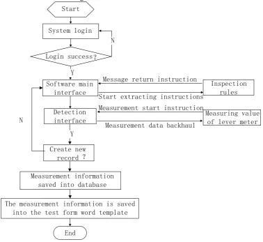
The upper computer software of the system is realized by C# language and developed by Visual Studio 2010 (Software Development Toolkit), Dreamweaver (Web Editor) and ORACLE 10g (Database) platform. The upper computer software collects the measurement data from the digital lever meter, and makes C and ORACLE establish a connection by writing code, and saves the measurement data in the ORACLE database. C# is used to automatically transfer the WORD version of the inspection form in the inspection procedure, and the data stored in the database is automatically written into the correct position in the Word template. And for the use of lever meter inspectors to authorize operations, no level, different roles for system access, editing and management permission settings, system users can only access their authorized resources. The flow chart of the lever reading system software test is shown in Figure 3.
Start
System login
Login success?
Software main interface
Measurement information saved into database
End
Inspection rules
Detection interface
The measurement information is saved into the test form word template
Y
N
Measuring value of lever meter Measurement start instruction
Measurement data backhaul Message return instruction
Start extracting instructions
Create new record ? N
[image:3.595.109.488.334.681.2]Y
Figure 3. Flow chart of software test for lever reading system.
measurement tool information and measurement specifications. Generate test information file and store it to the database, and provide the test interface at the same time.
At present, digital display lever meters with digital output capability have been partially put into use in the process of on-site quality inspection. However, lever meters produced by different gauge manufacturers have different data output interfaces and communication protocols, and need to install data acquisition software corresponding to brand gauges.
[image:4.595.113.498.241.368.2]This paper does not need to install the corresponding brand measuring tool data acquisition software, directly calls the bottom DLL in the detection interface to achieve wireless communication with the measuring tool. As shown in Figure 4, first click on the blank on the right side of the measurement interface, pop up the data input box, you can see the data from the LCD screen of the digital lever meter in real time into the data input box.
Figure 4. Lever reading system check interface.
public bool ValidGaugeSiLabsPair(string gauge, int id) { uint handle = 0;
handle = DLLImport.GetSiLabHandle((uint)id); if (handle == 0)
{ // Failed to open, validation failed return false; }
// Open successfully, continue to verify USB_Packet tmp = new USB_Packet(“test”); int nRet = DLLImport.Host_Request_Data(handle, ref tmp);
if (nRet != 1)
{ // Failed to read content, validation failed DLLImport.CloseSiLabs(handle); return false; } // Read successful, continue validation ... ...
Import data into Word to facilitate data generation of various report files, the measurement data into the Word table. In Microsoft Visual Studio 2010, there are many ways to manipulate Word using C and here we use the method of calling the Word class. To call the Word class in a program, you need to open the Reference project in the Project menu of the programming environment and select the Microsoft. Office. Interop. Word. DLL item in the project. Word has five large objects, Application represents the Microsoft Word application backbone; Document represents a Word document, Selection represents the currently selected region, and there are no selected region times for the cursor punctuation. Bookmarks stands for bookmarks; Range represents a region, but it is generally not visible. The specific procedures are as follows:
private static Microsoft.Office.Interop.Word.Application wordApp; private static Microsoft.Office.Interop.Word.Document wordDoc;
string pageSign = “Page m (N pages)”;//Generate start and end pages in document paging wordApp.Selection.PageSetup.LeftMargin = wordApp.CentimetersToPoints(float.Parse(“2.3”));
wordApp.ActiveWindow.ActivePane.HorizontalPercentScrolled = 11;
wordApp.Selection.PageSetup.RightMargin = wordApp.CentimetersToPoints(float.Parse(“2.3”)); //Setting document boundaries
Summary
This paper completes the development of digital lever meter wireless communication reading system, which can communicate with the computer USB port through Bluetooth. It realizes the two-dimensional drawings of CAPP system and PDF process file parsing and extracting into the database, which can conveniently and quickly use the inspection elements for measurement and guidance. It also realizes the display of measurement data on the flat panel and the W. Ord form generation simplifies the worker's operation process and actual workload, and provides real-time data support for production process monitoring and quality traceability. After testing without any additional software settings, the measured values on the gauge can be uploaded to the reading system quickly and accurately, providing reliable data sources for the related technical research of the Internet of Things, reducing the error caused by human factors.
Acknowledgement
This research was financially supported by the Technical Foundation (JSZL2015205A005).
References
[1] L. Ying, Discussion on industrial automation instrumentation and automation control technology, Low Carbon World. 26 (2015) 258-259.
[2] Z. Wei, C.Y. Hong and Y.Z. Long, Industrial instrument system based on remote data acquisition technology, Modern Mining. 26 (2015) 258-259.