ISSN: 1992-8645 www.jatit.org E-ISSN: 1817-3195
DEVELOPMENT OF AUTOMATED CLOSED-LOOP DRIVE
UPON DESIGNING OF ROLLER BIT DRILLING RIG FOR
OPEN PITS
1ANDREY OLEGOVICH SHIGIN, 2ANNA ALEKSANDROVNA SHIGINA, 3ANATOLII
VLADIMIROVICH GILEV, 4SERGEI ANTONOVICH VOKHMIN, 5GEORGII SERGEEVICH
KURCHIN
1345
Siberian Federal University, Prospekt Gazety Krasnoyarskiy Rabochiy, 95, Krasnoyarsk, 660025, Russia
2
Siberian Federal University, Vuzovskiy pereulok, 3, Krasnoyarsk, 660025, Russia
ABSTRACT
The system of manual and automated drilling control systems have been studied. An automated system has been developed which permits simultaneous tracking of variations of structural and strength properties of rock mass during drilling. Technological flowchart of operation of the considered system has been developed. The structure and mathematical dependences have been determined on the basis of which the drilling control system with subsystem of monitoring of rock properties operates. Maximum efficiency of rock destruction during roller drilling of boreholes has been studied as a function of drill bit rotation frequency, time of energy transfer leading to destruction of the required rock amount and feed thrust of working unit. The calculation procedure has been developed of optimum process variables of drill bit drilling of rocks with significant fracturing, lamination and varying drillability factor. Comparative analysis of increase in productivity of drilling rig as a consequence of application of automated system based on adaptive rotating-feeding device. The necessity to equip drilling rigs with automated intelligent system has been substantiated with capabilities to provide duly rapid response of the system to variations of working object properties and maintaining of optimum ratio of the adjusted process variables of "drilling rig--drill bit--rock ore" system. Execution of the aforementioned tasks by intelligent control system will make it possible to reduce drilling expenses and increase in operation efficiency of the mentioned flowchart.
Keywords: Automated Control System, Closed Loop, Adaptive Element.
1. INTRODUCTION
1.1 Problem description
An important role in automation and
management of technological processes in mining industry is played by control systems. The problem of development of such systems is sufficiently urgent nowadays, since an increase in control efficiency is impossible without application of automated control systems (ACS) based on application of information technologies and progressive mathematical control models [7], [11], [15], [17], [19].
However, modern ACSs of drilling rigs do not provide possibility to response rapidly to variation of properties of working object (rock), to adjust
operation modes and to compensate for
perturbations during operation of "drilling rig--drill bit--rock ore" complex system (hereafter, control target or DPS), which leads to decrease in its
efficiency. In addition, the existing ACSs have no possibility to adopt solutions on modification of variables during varying properties of the object, which prohibits consideration for the variety and complexity of the problems occurring during ACS operation [1], [3]. Provision of such challenges with regard to operability and accuracy of data transfer is the basic condition of increase in quality of object and process quality.
1.2 Approaches to the problem solution
This challenge can be met by equipment of drilling rig with automated intelligent system (AIS) with adaptive element aimed at two-fold increase in operation lifetime of expensive drilling tool, increase in efficiency and reducing drilling expenses.
The developed AIS makes it possible to trace
variation of properties of control target
ISSN: 1992-8645 www.jatit.org E-ISSN: 1817-3195
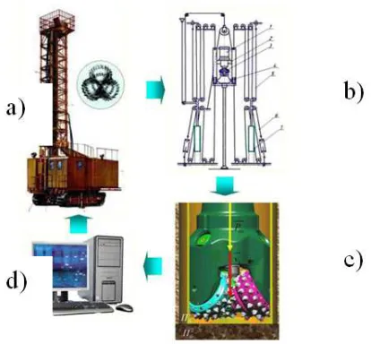
[image:2.612.91.298.182.374.2]adjust process variables in continuous mode, as well as to provide successful solution of the problems with a priori incompleteness and fuzziness of initial data, variability and inaccuracy of properties of the considered control target. The schematic layout of the developed intelligent monitoring system is illustrated in Fig. 1.
Figure 1. Technological Layout Of Intelligent Monitoring And Control System Of Process Variables Of Drilling
Rigs: A) Drilling Rig; B) Adaptive Rotating-Feeding Device; C) Drilling Tool; D) Computer.
Application of the developed forecasting
procedure of operation lifetime, optimum
productivity and specific expenses of technological
process, control and accounting of given
recommendations would increase the operation efficiency of DPS and decrease operational costs with varying properties of control target and impact loads [16]. Application of the mentioned procedures is required for implementation of algorithm and obtaining of certain forecast of operation of technical system.
A promising trend of development of artificial intellect is based on the works devoted to fundamentals of control theory of structural dynamics of complex engineering systems [4], [12], [18], [19]. The trend proposes application of complexes with various models, combined methods and algorithms, as well as development of intelligent technology of automated designing of monitoring and control systems pf complex technical objects under various conditions.
The process of monitoring and control analyzes the transition of the system structure from one state
to another under the action of various reasons (impact of medium, conflicting systems and so on).
The position of the control system of structural dynamics of complex engineering systems is defined as integration of artificial intellect into system analysis, investigation into procedures, control theory and system theory, that is, requires for interdisciplinary researches [4], [9], [10], [20]. The control concept of structural dynamics of complex engineering objects is reduced to the solutions of the following basic targets:
- analysis of structural dynamics of complex engineering system;
- estimation of structural state of the system;
- selection of optimum control programs and adjustment of the system structural dynamics.
For generalized intelligent system a structure is applied which interact with medium and, acquiring from it all necessary information, generates action target and analyzes impacts on the system (physical and informational). The master elements of control system in this case are intelligent converter and basic control system [2], [5], [6].
Mathematical model of intelligent control system is composed of three parts:
- intelligent converter;
- control target;
- system master device (computing, converting and executing units).
Intelligent converter modifies information about medium and control target and transforms into actuating signals to control units of the system. In order to generate impacts on the control system this converter involves decision making block.
ISSN: 1992-8645 www.jatit.org E-ISSN: 1817-3195 2. EXPERIMENT
2.1 Intelligent control system
Contrary to regular ACS, which is widely applied in various industries, autonomous operation of drilling rig requires for application of intelligent system, which together with master functions permit tracing of data flow about randomly varying properties of rock ore. Aiming at implementation of intelligent automate control on the basis of drilling rig, the hardware system should include adaptive
element of electromagnetic type, which
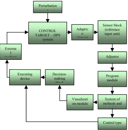
[image:3.612.91.299.287.498.2]simultaneously smoothes incidental impact loads and permits rapid response about time and impact level. Structural model of the proposed AIS with adaptive element is illustrated in Fig. 2.
Figure 2. Schematic View Of The Proposed AIS With Adaptive Element.
This systems operates on the basis of the following algorithm. External medium (rock mass: properties of drilling rock and their non-forecasted variations) acts on the target operation (drilling tool). This system assumes involvement of adaptive rotating-feeding device (auxiliary adaptive element) of drilling rig, sensor block, computer and controller module. The object of also affected by perturbations independent on the control system: impact load (a reason of variation of drilling rig operation mode), noises (vibrations, dusting level, temperature, instrumental errors, failure of control system). This adaptive element permits smoothing of these non-forecasted perturbations.
In order to analyze input data on variation of physico-mechanical properties of rock the sensors (reference input unit) send to computer data signals about variation of drilling rate and current in stator of adaptive mechanism (setting action). In computer these signal are converted into control signals (data on actual properties of rock and process variables) by means of controller module (adjustors, control units), intended for smoothing of short-time deviations and implementation of control process and program module, which includes the developed calculation procedures (implementation of control algorithm). Then the control signals are transferred to executing device, implementing the adopted solution and promoting variation of appropriate process variables (automatic adjustment). These procedures are applied for determination of forecasted operation lifetime of drilling tool and specific expenses of drilling, corresponding to actual values of process variables and rock properties. The same data are also used for determination of optimum drilling rate and process variables (output data). In order to improve the qualitative properties of the system the actual values are compared with the optimum values and are automatically modified using adjusting units.
The feedback is used for rapid data transfer (in 0.01 s) about current process variables control target from control target to control circuit. After adjusting actions the adaptive rotating-feeding device operates in newly set modes and feeds and rotates the drilling tool with required feed thrust and rate. Drilling tool passes through rock mass at preset rate up to next variation of rock properties. The calculated values are displayed on control panel by means of visualization module intended for demonstration of simulated results and further operator control.
The major structure of drilling automation
includes modules of data acquisition and
displaying, feed thrust adjustment, rotation
frequency and compressed air pressure. In addition, the system of drilling automation should be equipped with safety module responsible for determination of process variables in allowable range.
2.2 Data analysis and processing
The value of current in windings of linear electric motors or adaptive electromagnetic coupling in each time instant is detected by device and converted into actual value of rock mass drillability by means of direct mathematical dependence on current via adjustment index. The information about Control type
System of methods and
models Program module Adjustor Sensor block
(reference input unit) Adaptiv
e element
Visualizati on module
Decision-making block Executing
device Externa
l medium
CONTROL TARGET – DPS
system Perturbation
ISSN: 1992-8645 www.jatit.org E-ISSN: 1817-3195
drillability factor in each time instant is recorded as a curve and displayed as a function of actual values of drilling depth and time for specific borehole. When feeding is deactivated, recording is pause in order to preserve the fairness of information about the borehole lithological column. Using the means of radio- or satellite navigation, the position of the drilling rig during operation and each borehole is detected. Summing up the information about lithological columns of each borehole, 3D model of rock mass is automatically constructed, thus facilitating analysis of data containing actual values of drillability factor, shape of cracks, discontinuities and layers with various physicochemical properties. The information about the structure and properties of rock mass is applied for scheduling of explosive works, calculation of amount of explosive materials and determination of subsequent spreading of rock beds.
The automation system contains controllers and
computer for data processing, sensor for
measurement of drilling rate at each time instant, rotation frequency, vibration sensor. Depending on actual value of drilling rate and drillability factor determined by Eq. (1), the actual value of dynamic feed thrust is calculated. Depending on actual value of drillability factor, its variation after passing of about 10 cm, and roller bit diameter the optimum feed thrust is calculated. Upon deviation of actual value of feed thrust from the optimum one the thrust is adjusted by means of frequency converter or rerouting, synchronous adjustment of mechanical characteristic on two feeding electric motors.
2.3 Calculation of efficiency indices
The minimum consumption of compressed air for transport of the coarsest particles:
(
)
m/min,F
3 air ore d
tf s h
1
, 60 k 3
g 4 8 . 0 P 40 k d D D 4 K Q
s 2
2
o ρ ⋅
ρ ⋅ ⋅
− π =
(1) where К is the coefficient accounting for non-uniform flow rate along the shaft due to localized increased development, existing of caverns and water inflow to the borehole (К = 1.3 - 1.5); D1 is the drill bit diameter, m; Db and d are the diameters of borehole and drill pipes, respectively, m; ρore and ρair are the densities of rock ore and air, respectively, kg/m3; ks is the coefficient of slurry particle size depending on the rate of rock jointing and lamination, for fractured rocks of Mazulsky limestone mine ks = 8; Пd is the minimum value of drillability factor for this rock mass; for prismatic
particles ks is 0.805 (sandstone) and 1.40 (limestone); Ptf is the thrust force, MN.
Aiming at adjustment of rotation frequency of electric motor, computer initially stores the range of
allowable rotation frequency and reverse
dependence on the thrust force, also in allowable range, according to Eq. (2). The rotating electric motor is also adjusted by frequency converter. If the vibration sensors detect thigh level of vibration, the feed thrust and rotation frequency of drill rod string are simultaneously and smoothly decreased to allowable level. After decreasing of vibration the characteristics of motors are smoothly recovered to initial state (before increased vibration) in accordance with the calculated value of optimum feed thrust.
Minimum effective rotation frequency of drill rod string during drilling of rock mass of complex structure can be determined as follows:
[ ]
k ,2 2 2 h F D 10
N 94 . 0
n 1
1
d 3 1
8 ind
d d
d d rot
F F
F
F ⋅
∆ +
∆ + ⋅ ⋅ ⋅ ⋅ π ⋅
⋅ =
(2)
where N is the power of drilling rig actuator,
transferred via drilling tool for destruction of rock;
nrot is the rotation frequency of drill rod string, s-1;
D1 is the drill bit diameter, m; Fd is the drillability
factor, Fd =0.07⋅
(
σcomp+σshear)
+0,7γ; kind is theindentor shape factor (kind = 0.79 for the indentor
with rounded cylinder tip; kind = 0.47 for the
indentor with regular cone shape; kind = 0.7 for the
indentor with convex cone shape); h is the height of
tooth outside the profile of rim, m.
Feeding of compressed air and pumping of water into the borehole to remove drill fines is adjusted depending on drilling rate and variation rate of
drillability factor. Maximum capacity of
compressor and pump is adjusted proportionally to drilling rate and variation of drillability factor (which corresponds to increase in complexity of structure of rock mass and sludging up of well). Upon decrease in variation of drillability factor the minimum value of feeding of compressed air is calculated and set according to Eq. (3).
[ ]
([ ]
)( )
, k 2
2 2 2 v 2 v v 2
2 v v 2 600 L D z 6 P
3
1 1
s s
s tf
⋅ ∆ +
∆ + ⋅ − +
+ σ ⋅
⋅ ⋅ ⋅ =
ind d d
d d
d d
dr r
r
F F
F F
(3)
where z is the amount of rolling element in bearing;
ISSN: 1992-8645 www.jatit.org E-ISSN: 1817-3195
mm; Db is the ball diameter, mm; vd is the rock
drilling rate, m/s; vs is the rate of lowering of drilling
tip tooth to bottom, m/s; Fd is the drillability factor;
ΔFd is the variation of drillability factor of rock
mass, characterized by variation of strength
properties, violation of continuity and
homogeneity; [σdr] is the allowable stress for
material of rolling elements of drill bit bearing. Adjustment of feeding electric motors includes stepwise switching of motors to different power depending on the strength range in open pit. During operation of asynchronous feeding motors, in addition to short-term variations of drillability factor, long-term variations appear corresponding to transition to a layer with other physico-mechanical
properties. During long-term variations of
drillability factor the position of operation mode of asynchronous motors travels along their mechanical characteristics without automation tools. After that the thrust is adjusted by means of frequency converter in the aforementioned consequence.
3. RESULTS
3.1 Factors of inefficient operation of drilling rig
The properties of rock mass are varied during drilling. Therefore, maximum allowable feed thrust of drilling rig working tool becomes a variable. Operator of drilling rig without information about the structure of rock mass maintains maximum mechanical drilling rate intuitively and using previous experience of certain level. This level of drilling rate is different for different rocks, deposits, drilling conditions and so on. Herewith, it is possible to state that the operator chooses preferred values of feed thrust and rotation frequency. These values are always below the effective values (Eqs. (5), (10)) by a certain coefficient of assurance of axial thrust kas.P and rotation frequency kas.n. The value of assured axial thrust depends on qualification of the operator, but in any case kas.P < 0. This is the first factor of inefficient operation of drilling rig upon manual control of drilling process variables.
The assured rotation frequency according to observations is always in the region of inefficient operation of drill bit by the coefficient of assured values of rotation frequency kas.n, which is also kas.n < 0. This is the second factor of inefficient operation of drilling rig upon manual control of drilling process variables. If the first mentioned factor depends on the operator experience, then the second one is related with the absence of distinct recommendations.
The first two factors exist upon drilling of any rock. They have predetermined and constant pattern. Decrease in capacity can be determined by accounting for the aforementioned assurance coefficients depending on the operator experience.
3.2 Variation of drilling process variables
On the basis of observations over actions of drilling rig operators it should be mentioned that in the case of significant vibration one and the same procedures are implemented every time. The operator reduces feed thrust of working unit up to certain level and, if this is insufficient, reduces rotation frequency. The lack of instructions aimed at efficient adjustment of process variables forces intuitive implementation of such actions. As already proven, decrease in feed thrust is justified in this case, however, rotation frequency should be simultaneously increased rather than decreased. Significant vibration in drill rod string occurs not by reason of high rotation frequency, but due to coalescence of rotation frequency and eigen frequency of rock, characterized with its structure and strength. By this reason it is reasonable to slightly increase the rotation frequency with simultaneous decrease in the feed thrust.
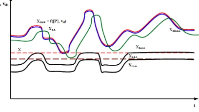
[image:5.612.317.521.482.597.2]Upon drilling of rock mass of complex structure the main attention is paid to the factors depending on response of operator to variation of properties of rock and time of transition processes. Variation of process variables by the operator, tracing all changes of rock properties, is illustrated in Figure 3:
Figure 3. Variation Of Thrust Of Drill Rod String During Drilling Of Rock Mass Of Complex Structure.
ISSN: 1992-8645 www.jatit.org E-ISSN: 1817-3195
response) with the use of automated system without adaptive subsystem; X is the straight line passing through the minimum values of allowable feed thrust (rock response); Xh.e.o. is the manual variation of feed thrust by highly experienced operator; Xl.s.o. is the manual variation of feed thrust by low skilled operator; Xs.a.s. is the strict control of feed thrust (rock response) of modern automated system, Atlas Copco.
The analysis of variation of process variables of drilling rig during drilling of rock mass of complex structure results in the following conclusions. The most efficient adjustment of feed thrust of working unit is provided by adaptive automated system. It repeats variations of maximum allowable feed thrust after variation of drillability factor Fd and rock structure with minimum assured feed thrust. Low response time makes it possible to approach maximum values of feed thrust. The existing automated system, Atlas Copco, providing strict control of steady level of feed thrust is inefficient due to missed increase in mechanical drilling rate in the time intervals demonstrated by extreme increases in allowable feed thrust (curve Xrock = f([P], Fd)).
Upon manual control highly experienced operator on the basis of instrument readings traces variations of current of feed drive or pressure in hydraulic system and varies the feed thrust (curve Xh.e.o), trying to approach it as much as possible to minimum values of allowable feed thrust (rock response), indicated by X curve. Low skilled operator also traces the instrument readings and attempts to approach the feed thrust to minimum allowable feed thrust (rock response) (curve Xl.s.o). However, the insufficient practical experience is compensated by certain assured axial thrust, which can be accounted for by a coefficient of assured axial thrust kas.P.
If an automated system is used, which monitors the rock properties, for instance, by pressure in hydraulic system or power consumption by drilling rig, but without adaptive subsystem, then in all cases there will exist significant delay of adjustments of feed thrust (curve Xa.s.), which leads to overriding of axial thrust beyond the allowable actual values.
The efficiency of mechanical drilling control by highly-experienced operator is slightly higher than that of automated system of strict control of steady feed thrust. This difference can vary under various drilling conditions. Taking into account tiredness, low skills and other human factors, the mentioned
control systems are comparable in terms of efficiency.
Therefore, the difference between the efficiency of adaptive automated system and manual drilling control system (system of strict control of steady feed thrust) can be estimated as integral sum of differences of mechanical drilling rate between the curves Xs.a.s. and Xad..a.c in the time interval t.
3.3. Comparative calculation of process variables of drilling rig with adaptive automated system and manual control system
Provided that the drilling rate is determined by the equation: 2 1 d rot at D F n P 40 v ⋅ ⋅
= , m/h,
(4)
and the allowable feed thrust by the Eq. (5):
[ ]
([ ]
) ( ) , k 2 2 2 2 v 2 v v 2 2 v v 2 600 L D z 6 P 3 1 1 s s s d at ⋅ ∆ + ∆ + ⋅ − + + σ ⋅ ⋅ ⋅ ⋅ = ind d d d d d dr r r F F F F (5)then the minimum allowable feed thrust under drilling conditions applied to specific drilled rock mass will be:
[ ]
[ ]
( ) ( ) 3 max min 1 max min 1 s s s at k 2 2 2 2 v 2 v v 2 2 v v 2 600 L D z 6 P ⋅ ∆ + ∆ + ⋅ − + + σ ⋅ ⋅ ⋅ ⋅ = ind d f d d d d dr r r min F F F F (6)and the maximum allowable feed thrust under drilling conditions applied to specific drilled rock mass will be:
ISSN: 1992-8645 www.jatit.org E-ISSN: 1817-3195
[ ]
[ ]
[ ]
2 P P
P at at
at max min av + = . (8) Or: [ ] ( [ ] ) ( ) ∆ + ∆ + + ⋅ ⋅ − + + σ ⋅ ⋅ ⋅ ⋅ = 3 max min 1 max min 1 3 s s s at 2 2 2 1 1 k 2 v 2 v v 2 2 v v 2 600 2 L D z 6 P d d d d ind d d dr r r av F F F F .
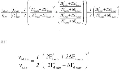
The drilling rate ratio of drilling rig with adaptive automated system and manual control system is:
[image:7.612.89.300.253.380.2][ ] [ ] 3 max min 1 max min 1 3 max min 1 max min 1 max min 1 max min 1 3 max min 1 max min 1 at at 2 2 2 2 1 2 2 2 2 2 2 2 2 2 2 1 P P v v ∆ + ∆ + ⋅ = ∆ + ∆ + ∆ + ∆ + + ∆ + ∆ + ⋅ = = d d d d d d d d d d d d d d d d min m s.a.s ad.a.s F F F F F F F F F F F F F F F F . or: 3 max min 1 max min 1 2 2 2 2 1 v v ∆ + ∆ + ⋅ = d d d d s.a.s ad.a.s F F F F (9) Upon drilling of rock mass of complex structure the main attention is paid to the factors depending on adjustment of rotation frequency of drill rod string in the case of variation of rock properties. Variation of rotation frequency of drill rod string by operator, tracing all changes of rock properties, is illustrated in Fig. 4.
Figure 4. Variation Of Rotation Frequency Of Drill Rod String During Drilling Of Rock Mass Of Complex
Structure
Figure 4 illustrates variations of rotation frequency of drilling rig working unit during drilling of rock mass of complex structure, where Xrock is the variation of maximum allowable rotation frequency resulting from variation of drillability factor Пd and rock structure; Xad.a.s is the variation of rotation frequency with the use of adaptive automated system; X is the straight line
passing through the minimum values of allowable rotation frequency; Xh.e.o, Xl.s.o is the curve of manual control of steady rotation frequency of working unit by highly-experienced or low-skilled operator; Xs.a.s. is the strict control of rotation frequency by means of modern automated system, Atlas Copco.
Concerning adjustment of rotation frequency of
drill rod string, nowadays no definite
recommendations are available. As shown above (Eq. (10)), during drilling of rock mass of complex structure there exists certain minimum allowable actual value of rotation frequency of drill rod string. In this mode drill bit operates efficiently in terms of productivity and operation lifetime. On the basis of practical observations operators in all cases of significant vibrations decrease rotation frequency, eliminating system resonance. This leads to significant loss in productivity and decrease in operation lifetime of drill bit. Rotary drill bit upon decrease in rotation frequency starts to act as impact bit, which affects adversely on the operation lifetime of rolling elements in the drill bits. For rotary drilling tool the maximum rotation frequency is determined by frictional heating from bearings. Due to numerous factors influencing on lifetime of rolling bearings upon increase in rotation frequency, it is recommended to maintain the rotation frequency above the highest allowable minimum value [nrot] (Fig. 4), but not to exceed
significantly the recommendations by the
manufacturer. In the case of significant vibration it is recommended to increase rotation frequency of drill rod string with simultaneous decrease in feed thrust according to Eq. (5), after decrease in rotation frequency it is required to approach the rotation frequency to the allowable minimum value [nrot] and to maintain it above the latter.
Generally the adjustment of rotation frequency consists of maintaining of certain value and its short decrease (not shown) with recovery of initial value.
The difference between the efficiency of adaptive automated system and manual drilling control system (system of strict control of steady rotation frequency) can be estimated as integral sum of differences of mechanical drilling rate between the curves Xs.a.s. and Xad..a.c in the time interval t.
Provided that the allowable rotation frequency is determined by Eq. (10):
[ ]
k , [image:7.612.91.298.476.594.2]ISSN: 1992-8645 www.jatit.org E-ISSN: 1817-3195
the ratio of drilling rates of drilling rig with adaptive automated system and manual drilling control system during adjustment of rotation frequency of working unit can be determined as follows:
[ ]
[ ]
[ ]
min max min s.a.s. ad.a.s.с 2 rot rot rot n n n v v ⋅ + == ,[ ]
k ,2 2 2 h F D 10 N 94 . 0 n min max 1 min max 1 m 3 1 8 ind d d d d d min rot F F F F ⋅ ∆ + ∆ + ⋅ ⋅ ⋅ ⋅ π ⋅ ⋅ =
[ ]
k .2 2 2 h D 10 N 94 . 0 n max min 1 max min 1 m 3 1 8 ind d d d d d max rot F F F F
F +∆ ⋅
∆ + ⋅ ⋅ ⋅ ⋅ π ⋅ ⋅ = Then: max min 1 max min 1 min max 1 min max 1 max min 1 max min 1 min max 1 min max 1 2 2 2 2 1 2 2 2 2 F 2 2 2 2 2 2 v v d d d d d d d d d d d d d d d d s.a.s ad.a.s F F F F F F F F F F F F F F F ∆ + ∆ + ⋅ = ∆ + ∆ + ⋅ ∆ + ∆ + + ∆ + ∆ + = (11) 4. DISCUSSION
In the case of Chernogorsk open pit coal mine the ratio of drilling rates of drilling rig with adaptive automated system and manual drilling control system with accounting for Eq. (9) is:
315
.
2
8
2
2
8
2
2
2
2
1
3 s.a.s.ad.a.s
=
+
⋅
⋅
+
⋅
⋅
=
v
v
Therefore, the average drilling rate due to appropriate adjustment exclusively of feed thrust with the adaptive automated system in Chernogorsk open pit coal mine can be increased by 2.315 times.
In the mines of Polyus Gold Mining Company the rigs drill rock mass with the hardness up to f = 16 according to Prof. Protodyakonov. The rock mass in these deposits is characterized with significant jointing. Then:
.
507
.
1
16
10
2
16
2
10
2
2
1
3 s.a.s.ad.a.s.
=
+
⋅
⋅
+
⋅
⋅
=
v
v
Therefore, the average drilling rate due to appropriate adjustment exclusively of feed thrust with the adaptive automated system in the open pit
mines of Polyus Gold Mining Company can be increased by 50.7 %.
In the kimberlite mines of ALROSA Company (Yakutia) the rock hardness reaches f = 12 according to Prof. Protodyakonov. The rock mass in these deposits is characterized with significant jointing. Then:
.
687
.
1
12
6
2
12
2
6
2
2
1
3 s.a.s ad.a.s=
+
⋅
⋅
+
⋅
⋅
=
v
v
The average drilling rate due to appropriate adjustment exclusively of feed thrust with the adaptive automated system in the kimberlite mines of ALROSA Company (Yakutia) can be increased by 68.7 %.
Thus, it is possible to conclude that the most significant increase in the drilling rate can be achieved at lower minimum values of hardness (drillability factor) in rock mass and high differences of boundary layers or at apparent jointing.
In the case of Chernogorsk open pit coal mine the ratio of drilling rates of drilling rig with adaptive automated system and manual drilling control system with accounting for Eq. (11) is:
833 . 0 8 2 2 8 2 2 2 2 1 s.a.s. s. a. ad. = + ⋅ ⋅ + ⋅ ⋅ = v v .
Therefore, the average drilling rate due to appropriate adjustment exclusively of rotation frequency with the adaptive automated system in Chernogorsk open pit coal mine can be increased by 83.3 %.
For Polyus Gold Mining Company:
615 . 0 6 10 2 6 2 10 2 2 1 s.a.s ad.a.s. = + ⋅ ⋅ + ⋅ ⋅ = v v .
The average drilling rate due to appropriate adjustment exclusively of rotation frequency with the adaptive automated system in the open pit mines of Polyus Gold Mining Company can be increased by 61.5 %.
For ALROSA Company:
667 . 0 6 6 2 6 2 6 2 2 1 s.a.s. ad.a.s. = + ⋅ ⋅ + ⋅ ⋅ = v v .
ISSN: 1992-8645 www.jatit.org E-ISSN: 1817-3195
the adaptive automated system in the case of ALROSA Company can be increased by 66.7 %.
5. CONCLUSIONS
In conclusion it is possible to mention the necessity to use AIS in drilling rigs for rapid and duly response of the system to variation of properties of control target and subsequent adjustment and maintaining of the system operation
parameters in optimum ratio. Further on,
application of such AIS would permit to
comprehensively assess physico-mechanical
properties of rock and to reduce operational costs of drilling under uncertain conditions and, as a consequence, to increase the system operation efficiency.
The presented calculation procedures reflect physical processes of roller bit drilling, reveal
optimum values of process variables and
subsequently should provide the basis for program module of intelligent drilling control system.
6. ACKNOWLEDGMENTS
The work was supported by the grant from the President of Russian Federation # МК-2531.2014.8 and the program of Ministry of Science and Education of Russian Federation titled “High-performance computing of complex algebraic systems and their applications”.
The authors are grateful to Dr. A.V. Gilev of SFU for his guidance and insights, which greatly assisted during the first steps toward studying the issues related to drilling machines.
REFERENCES:
[1] E. B. Andreev and V. E. Popadko. (2005).
Technical means of control systems of technological processes of oil and gas industry. Moscow: "Oil and Gas", Gubkin Russian State Oil and Gas University.
[2] S. V. Afanasieva. (2013). Technology of
intelligent data analysis. Moscow: Higher School of Economics.
[3] E. I. Gromakov. (2010). Automation of oil and
gas technological processes. Tomsk: TPU Publishing House.
[4] M. Yu. Okhtilev, B. V. Sokolov, and R. M.
Yusupov. (2006). Intelligent technologies of
monitoring and management of structural dynamics of complex technical objects. Moscow: Nauka.
[5] S. N. Pavlov. (2011). Systems of artificial
intellect (Part 1). Tomsk: El Content.
[6] K. A. Pupkov and V. G. Kon'kov. (2003).
Intelligent systems. Moscow: Publishing House of Bauman Moscow State Technical University.
[7] N. N. Sashchenko. (2006). Intelligent adaptive
system if data transfer in distributed automated control systems (PhD thesis). Institute of Engineering Physics, Vladimir, Russia.
[8] I. Yu. Tyukin and V. A. Terekhov. (2008).
Adaptation in non-linear dynamic systems
(Series: Synergetics: from the past to the future). Saint Petersburg: LKI.
[9] Dersin, P. (2014). Systems of Systems,
IEEE-Reliability Society. Technical Committee on “ Systems of Systems”.
[10] James, J., Cellier, F., Pang, G., Gray, J. and Mattsson, S. E. (1995). The State of
Computer-Aided Control System Design (CACSD), In the
Proceedings of the Conference – IEEE Control Systems.
[11] Juarrero, A. (2002). Dynamics in Action: Intentional Behavior as a Complex System.
Emergence, 2 (2), pp. 24–57.
[12] Rogers, E.M., Medina, U.E., Rivera, M.A., and Wiley, C.J. (2005). Complex Adaptive Systems
and the Diffusion of Innovations. The Public
Sector Innovation Journal, 10 (3), pp. 1-26. [13] Ross, A.M., Rhodes, D.H., and Hastings D.E.
(2008). Defining Changeability: Reconciling
Flexibility, Adaptability, Scalability,
Modifiability, and Robustness for Maintaining
System Lifecycle Value. Systems Engineering
Wiley Periodicals, Inc., pp. 1-24.
[14] Sgurev, V., Vassilev, V., Dokev, N., Genova, K., Drangajov, S., Korsemov and Atanassov, A. (1989). TRASY – An automated system for real-time control of the industrial truck haulage
in open-pit mines. European Journal of
Operational Research, 43 (1), pp. 44–52. [15] Ceravolo, R., Tondini, N., Abbiati, G. and
Kumar, A. (2012). Dynamic characterization of complex bridge structures with passive control
systems. Structural Control and Health
Monitoring, 19 (4), pp. 511–534.
[16] Stupina, A.A., Shigin, A.O., Shigina, A.A.,
Karaseva, M.V. and Korpacheva, L.N. (2014). Control and management by resource of rolling
cutter bits in drilling rock massif. Middle-East
ISSN: 1992-8645 www.jatit.org E-ISSN: 1817-3195
[17] Tianyou, C., Hong, W., Qin, S. J., Tongwen, C. and Sirish, L. S. (2014). Guest Editorial
Integrated Optimization of Industrial
Automation, IEEE transactions on automation
science and engineering, 11 (4), pp. 963-964. [18] Vespignani, A. (2012). Modelling dynamical
processes in complex socio-technical systems.
Nature Physics, 8, pp. 32-39.
[19] Zaitsev, K.S. (2003). Using Group Technology to Plan Data Processing in Computer-aided
Control System. Automatic and Remote Control,
64 (9), pp. 1507-1512.
[20] Zelentsov, V., Sokolov, B., Brovkina, O. and Mochalov, V. (2014). Methodological and Technological Foundations of Remote Sensing Monitoring and Modelling of Natural and
Technological Objects. Information Technology