2015
DESIGN AND ANALYSIS OF DIFFERENT SUBSTRATE
MATERIALS FOR UWB ANTENNA USED FOR
BIOMEDICAL APPLICATIONS
K.RAJKAMAL1*, GOVARDHANI.IMMADI2
1. Research Scholar, Dept Of ECE, KLEF, Vaddeswaram, Guntur, A.P, India. *..Associate Professor, Dept Of ECE, Guntur Engineering College, Guntur, A.P, India.
2. Professor Department Of ECE, KLEF, Vaddeswaram, Guntur, A.P, India.
[email protected] [email protected]
ABSTRACT
A CPW fed Micro strip patch antennas of size 25 x 25 x 1.6 mm3 is proposed. The antennas are designed
and analysed with different materials like FR4, RT Duroid, Polyester and Fleece. The proposed antenna possess a method to minimize the monopole patch antenna by loading the U strip over the predictable monopole patch antenna to lower the height of the antenna. The ground was vertically extended toward two sides of the single radiator. The antenna is simulated using MOM based CST microwave Studio. The antenna is practically fabricated. Measured results show a good concurrence with simulated results. The operating frequency band is 3-12 GHz (9 GHz) good agreement interms of return loss, Radiation pattern and VSWR. The designed structure is suitable for wireless and as well as biomedical applications[4][16].
Ketwords:Biomedical materials, coplanar wave guide, Micro strip patch antenna, Ultra-wideband
1.
INTRODUCTION
In this era, antennas are an necessary part of any wireless communication system (WCS), with the technological advancements; antennas are playing even a bigger role. Due to the more developments in WCS, there is a demand for broadband antennas with high gain and bandwidth covering all frequency ranges [1]. Researchers have examined the dissimilar structures that can attain an UWB[28][30]. The micro strip UWB antennas have concerned much attention to their advantages like simple structure, low profile, high data rate, easy integration and easy fabrication. The UWB antenna mainly used for short range (10 m) high data WCS applications, peer to peer ultra fast communications and more applications. Due to this more applications the researchers dwell deep in the design of UWB antennas. Several monopole antennas, such as rectangular, rectangular patch and various slot antennas have been reported for compact UWB antenna. UWB band has been considered more effective for biomedical applications because of its high frequency bandwidth, which in terms allows the wavelength to be smaller as well to receive a higher bit rate
after the practical antenna implementation [8][24][25].
As per the regulations of FCC stated on February 14 , 2002, frequency allocation for UWB is from 3.1GHz to 10.6GHz with a bandwidth of 7.5Ghz. UWB communication uses wireless communication with any modulation technique. Generally in UWB wireless communication data can be sent only in the form of short pulses of narrow with, so that the transmitting power for UWB communication is very less is less than 10% of Narrow band communication. Because of these alluring properties, UWB technology is widely use in many applications such as indoor positioning, radar/medical imaging and target sensor data gathering[2][6][7].
The UWB antenna will plays a major role in different wireless applications,
instead this the
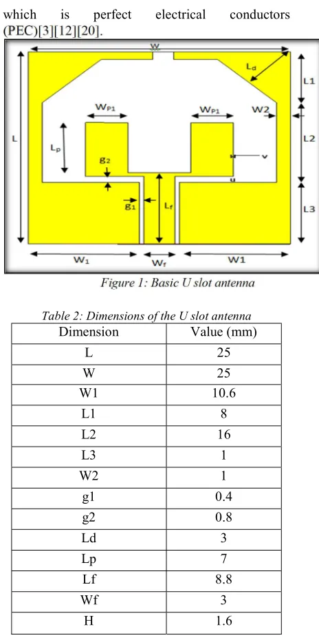
2016 generally available dielectric substrates like FR-4 and RT-Duroid, two biomedical material substrates of polyester and fleece[15][19][26]. The Basic Antenna design for considered for further analysed is shown in the figure 1 and the material properties are shown in table.1.
[image:2.612.311.543.89.554.2]2.
ANTENNA DESIGN
Table 1: Substrate materials used for proposed designs
S.N
O
Materi
als
used
Dielect
ric
constan
t
Thickne
ss (mm)
Loss
tange
nt
1
RT-Duriod
2.2
1.6
0.000
9
2
FR-4
4.3
1.6
0.025
3
Polyest
er
3.2
1.6
0.002
9
4
Fleece
1.3
1.6
0.025
A.SUBSTRATE MATERIALS
SELECTION
The permittivity of a substance is usually given comparative to that of free space which is known as relative permittivity or dielectric constant Єr. Different substrates having different dielectric constants and loss tangent affect the antenna concert in various ways[18][22]. Here, Fleece fabric with Єr =1.3, δ=0.025. Polyester with Єr =3.2, δ=0.0029.Rt Duroid withЄr=2.2, δ=0.0009. FR-4 with Єr =4.3, δ=0.025 are used as antenna substrates. Selection of material for designing the antenna is unique in this paper. Fleece fabric is outstanding in clothing, absorbency, durability, and flexibility. It is less flammable too. Properties of the fleece substance is pleasant to touch, very warm and provides warmth without weighing a lot, dries quick, never loses its properties during use, looks
good-looking, and very good
hygroscopic[9][10][21]. On the other hand Polyester includes high tensile strength, high resistance to stretching, durability and terrific electrical property whereas FR-4 is the primary insulating backbone upon which the huge majority of rigid printed circuit boards (PCBs) are produced. It is a compound substance composed of woven fibreglass cloth with an epoxy resin binder that is fire resistant. The patches are made of threads
which is perfect electrical conductors (PEC)[3][12][20].
Figure 1: Basic U slot antenna
Table 2: Dimensions of the U slot antenna
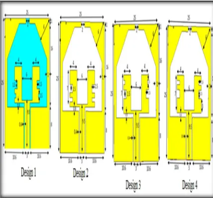
In this work, first considering the Basic U slot CPW antenna is as shown in fig.1 and their dimensions are included in Table 2. Based on the current distributions of the radiating element the patches are modified are shown in fig.2. In fig 2 the ground is same as that of the basic U slot antenna. The shape of the U slot is modified from design 1 to design 4. In design 1, the irregular U slot is modified by etching of two stubs (one in the centre of left and right rectangles with stub 1 dimensions and another stub with dimensions of the stub 2 at the lower middle parts of the two rectangle sides of
Dimension Value (mm)
L 25
W 25
W1 10.6
L1 8
L2 16
L3 1
W2 1
g1 0.4
g2 0.8
Ld 3
Lp 7
Lf 8.8
Wf 3
2017 the U slot shown in the Design 1, the dimensions of the stubs are shown in table 3). Modification of Design 1 with the lower stub 2 dimensions with stub 3 dimension in the lower part for getting Design 2. Up to Design we are concentrating on lower part etching, the Design 3 and Design 4 are Upper part etching with the reciprocal to the Design 1 and Design 2. From Design 1 to Design4, all the designing and simulations are carried out in MOM based CST Microwave Studio. With the substrate material properties are shown in Table 1 and the radiating element used is copper[6][11][17].
[image:3.612.91.305.262.461.2]Figure 2: Proposed Antenna Design
Table 3: 3 Dimensions of the stubs
3. EXPERIMENTAL
RESULTS AND DISCUSSIONS
The Design 1 to Design 4 are Designed and simulated using MOM based 3D EM Simulator. These four antennas are implemented using the four different substrates (two generally
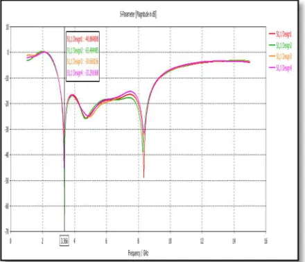
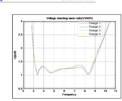
available materials of FR4, RT Duroid and two biomedical materials polyester and fleece)[13][16][27]. From the fig3 (a-c) shows the simulation Results of return loss, VSWR and Radiation pattern of proposed antennas of fig 2 are implemented using the RT Duroid material. The simulation result shows the best result of 3.5-12 GHz operating frequency of antenna and the bandwidth of 8.5 GHz with return loss -49 dB at the frequency 8.35 GHz obtained for design 4[4][29].
Fig 3(a): Return loss parameter performance of proposed antennas with RT Duroid material
Fig 3(b): VSWR parameter performance of proposed antennas with RT Duroid material
S.No Stub Dimension (length x depth)
1 stub 1 1.5 x 1.5
2 stub 2 0.75 x 0.75
[image:3.612.335.567.468.628.2]2018 Fig 3(c): Two Dimensional radiation pattern
performances of proposed antennas with RT Duroid material
From the fig 4(a-c) shows the simulation Results of return loss, VSWR and Radiation pattern of proposed antennas of fig 2 are implemented using the FR4 material. The simulation result shows the best result of 3.5-12 GHz operating frequency of antenna and the bandwidth of 8.5 GHz with return loss -63.4844 dB at the frequency 3.36 GHz of Design 4 gets
Fig 4(a): Return loss parameter performance of proposed antennas with FR4 material
Fig 4(b): VSWR parameter performance of proposed antennas with FR4 material
Fig 4(c): Two dimensional radiation pattern
performances of proposed antennas with FR4 material
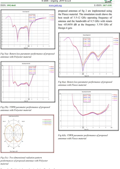
[image:4.612.77.529.67.265.2] [image:4.612.329.554.357.516.2] [image:4.612.80.300.455.644.2]2019 Fig 5(a): Return loss parameter performance of proposed antennas with Polyester material
Fig (5b): VSWR parameter performance of proposed antennas with Polyester material
Fig (5c): Two dimensional radiation pattern performances of proposed antennas with Polyester material
From the fig 6(a-c) shows the simulation Results of return loss, VSWR and Radiation pattern of
proposed antennas of fig 2 are implemented using the Fleece material. The simulation result shows the best result of 3.5-12 GHz operating frequency of antenna and the bandwidth of 8.5 GHz with return loss -45.0850 dB at the frequency 3.338 GHz of Design 4 gets
Fig 6(a): Return loss parameter performance of proposed antennas with Fleece material
[image:5.612.88.553.58.710.2]2020 Fig 6(c): Two dimensional radiation pattern
performances of proposed antennas with Polyester material
A.
Validation of proposed antennas
[image:6.612.88.332.70.252.2]The proposed antennas are fabricated and tested. Due to easily availability with low cost of FR4, we fabricate the proposed antennas and the fig 7 shows the fabricated prototypes. For measuring the return loss and VSWR parameter of the proposed antennas uses the VNA (Vector Network Analyzer). The measured return loss and VSWR parameter shown in fig 8(a & b)[23][25].
Fig 7: prototypes of proposed antennas with FR4 material.
Fig 8(a): validation of Return loss parameter of proposed antennas of FR4 material
Fig 8(b): validation of VSWR parameter of proposed antennas of FR4 material
4.COMPARATIVE STUDY OF THE
PROPOSED MODELS:
[image:6.612.322.579.81.294.2] [image:6.612.334.563.362.552.2] [image:6.612.91.305.449.641.2]2021 9.3657 GHz with minimum return loss of -31.127dB, VSWR 1.Model 4 resonates at 3.0253 GHz to 9.2482 GHz with minimum return loss of -44.809dB, VSWR 1.262.as per the observations second model is best suited model for ultra wide band applications.
5.CONCLUSION
A new CPW fed compact UWB antenna with four different slots are proposed. The antennas are designed using four different materials, two materials are generally available FR4 and RT Duroid and other two are biomedical materials like Polyester and Fleece. The simulations are carried for all four materials with four different structures. The simulation results are good agreement in terms of Return loss, VSWR and radiation pattern. Four different patch slot antennas are fabricated using the FR4 substrate due to its low cost. The fabricated prototype is good agreement with simulated return loss and VSWR parameter. The proposed antennas are used for any UWB applications. Major limitation of ultra wide band antenna for biomedical applications is its low gain. Gain enhancement can be possible by using optimisation methods.
6.FUTURE SCOPE:
Antenna is basically designed for bio medical applications. Extend this work by replacing the dielectric substrate with bio implantable material for biomedical applications. Also test the antenna with other feeding network.
ACKNOWLEDGMENT
The authors like to convey their thanks to the department of ECE and the management of K L University for their support and encouragement during this work.
REFERENCES:-
[1]. Federal Communications Commission, Washington, DC, USA, “Re-vision of Part 15 of the commission’s rules regarding ultra-wide-band transmission systems First Report and Order FCC 02.V48,” Tech. rep., 2002.
[2]. “FCC report and order for Part 15: Acceptance of ultra wideband (UWB) systems from 3.1– 10.6 GHz,” FCC, Washington, DC, USA, 2002.
[3]. “Federal communications commission: revision of part 15 of the commission's rules regarding ultra-wideband transmission system from 3.1 to 10.6GHz,” in Federal
Communications Commission, pp. 98–153,
Docket, Washington, DC, USA, 2002, ET-Docket.
[4]. G.Z.Rafi and L. Shafai, “Wideband-slotted diamond-shaped mi-crostrip patch antenna,” Electron. Lett., vol. 40, no. 19, pp. 1166–1167, Sep. 2004.
[5]. C. Balanis, Antenna Theory: Analysis and Design. John Wiley & Sons, 2005.
[6]. W. Sörgel and W. Wiesbeck, “Influence of the Antennas on the Ultra Wideband Transmission,” EURASIP Journal on Advances in Signal Processing, 2005.
[7]. 7. A. Alomainy, Y. Hao, C. G. Parini, and P. S. Hall, “Comparison between two different antennas for UWB on-body propagation measurements,” IEEE Antennas Wireless Propag. Lett., vol. 4, pp. 31–34, 2005.
[8]. . S. Gupta, M. Ramesh, and A. T. Kalghatgi, “Design of optimized CPW fed monopole antenna for UWB applications,” in Proc. Asia-Pacific Microw Conf. Proceedings (APMC), Dec. 4–7, 2005, vol. 4, p. 4.
[9]. . B. Sanz-Izquierdo, J. C. Batchelor, and M. I. Sobhy, “Compact UWB wearable antenna,” in Proc. Loughborough Antennas Propag. Conf.
(LAPC), Apr. 2–3, 2007, pp. 121–124.
[10]. . H. K. Yoon, W. S. Kang, Y. J. Yoon, and C.-H. Lee, “A CPW-fed flexible monopole antenna for UWB systems,” in Proc. IEEE Int. Symp. Antennas Propag. Soc., Jun. 9–15, 2007, pp. 701–704.
2022 [12]. . W. Wiesbeck, G. Adamiuk, and C.
Sturm, “Basic Properties and Design Principles of UWB Antennas,” Proceedings of the IEEE, vol. 97, no. 2, pp. 372 –385, Feb. 2009.
[13]. . N. Chahat, M. Zhadobov, R. Sauleau, and K. Ito, “A compact UWB antenna for on-body applications,” IEEE Trans. Antennas Propag., vol. 59, no. 4, pp. 1123–1131, Apr. 2011.
[14]. . K. Baskaran, C. P. Lee, and C. K. Chakrabarty, “A compact microstrip antenna for ultra wideband applications,” Eur.
J.Scientif. Res., vol. 67, no. 1, pp. 45–51, 2011.
[15]. . PSR Chowdary et.al; " On the Multiband and Miniaturization Characteristics of Sierpinski Fractal based Patch Antenna for Wireless Applications ," Springer -Telecommunications Systems Journal, Accepted. ISSN: 1018-4864.
[16]. P.J.Soh,G.A.E.Vandenbosch,S.L.Ooi, and M.R.N.Husna,“Wearable dual-band Sierpinski Fractal PIFA using conductive fabric,”
Electron. Lett., vol. 47, no. 6, pp. 365–367,
Mar. 2011.
[17]. P. J. Soh, S. J. Boyes, G. A. E. Vandenbosch, Y. Huang, and S. L. Ooi, “On-body characterization of a dual-band, all textile PIFA,” Progr. Electromagn. Res.
(PIER), vol. 129, pp. 517–539, 2012.
[18]. . S. J. Boyes, P. J. Soh, Y. Huang, G. A. E. Vandenbosch, and N. Khiabani, “On-body performance of dual-band textile antennas,”
IET Microw., Antennas, Propag., vol. 6, no.
15, pp. 1696–1703, Dec. 2012.
[19]. . Lilja, P. Salonen, T. Kaija, and P. de Maagt, “Design and manufacturing of robust textile antennas for harsh environments,” IEEE
Trans. Antennas Propag., vol. 60, no. 9, pp.
4130–4140, Sept. 2012.
[20]. . Z. Ihsan and K. Solbach, “Frequency Invariant Far-Field Beam Pattern of UWB Printed Circular Monopole Antenna Array,” in German Microwave Conference (GeMiC), March 2012.
[21]. . Anil Kr Gautam, Swati Yadav, Binod Kr Kanaujia, “A CPW-Fed Compact UWB Microstrip Antenna” IEEE ANTENNAS
AND WIRELESS PROPAGATION
LETTERS, VOL. 12, 2013.
[22]. . Rezaul Azim, Mohammad Tariqul Islam, Norbahiah Misran, Baharudin Yatim, and Haslina Arshad, “Design and Realization of a Planar Ultrawideband Antenna with Notch Band at 3.5 GHz,” The Scientific World Journal, vol. 2014, Article ID 563830, 7 pages, 2014
[23]. . Martins.C. Ezuma, Santosh Subedi, and Jae-Young Pyun ” Design of a Compact UWB Antenna for Multi-band Wireless Applications” IEEE ICOIN pp. 456-461, 2015.
[24]. Narbada Prasad Gupta, Mithilesh Kumar “Radiation Performance Improvement in Wearable UWB Antenna through Slot Insertion Technique” IEEE CSNT PP. 83-87, 2015 .
[25]. Dawar Awan, Husan Ali, Shahid Bashir, Muhammad Asif “Relative Size Reduction Technique to design miniaturized UWB Antennas,” International Conference on Microwave and Millimeter Wave Technology (ICMMT), IEEE, vol.1, pp.223-225, 2016
[26]. Akash Biswas, Akib Jayed
Islam, Abdullah Al-Faruk, Sadman Shahriar Alam “Design and erformance analysis of a microstrip line-fed on-body matched flexible UWB antenna for biomedical applications,” International Conference on Electrical, Computer and Communication Engineering (ECCE), IEEE, pp.181-185, 2017 [27]. Kawshik Shikder, Farhadur Arifin “A
novel UWB wearable icon-type textile antenna for WBAN applications,” International Conference on Electrical, Computer and Communication Engineering (ECCE), IEEE, pp.886-890, 2017.
[28]. .M. Venkata Narayana,
Govardhani.Immadi, Dr.Habibulla Khan,N. Suryateja, D. Manasa,” Reduction Of Mutual Coupling In Antenna Arrays By Sparse Antenna”, International Journal of Pure and Applied Mathematics, Volume 115 No. 7 2017, 465-469, ISSN: 1311-8080 (printed version); ISSN: 1314-3395 (on-line version).
[29]. .M. Venkata Narayana,
2023
Chowdary, M. Emmanuel Raju,
“Enhancement Of Bandwidth Of Electrically Small Antenna Using Spiral Resonator And Loop Feed”, International Journal of Pure and Applied Mathematics, Volume 115 No. 7 2017, 471-476, ISSN: 1311-8080 (printed version); ISSN: 1314-3395 (on-line version).
[30]. .M. Venkata Narayana,
2024
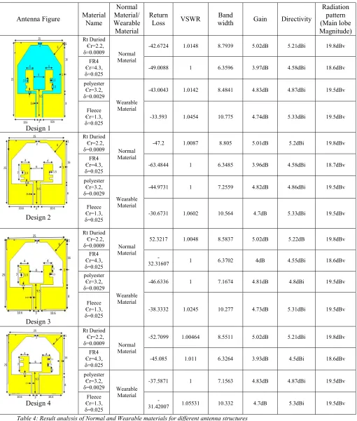
The observation results of four antennas with four different materials are shown in table 4.
Antenna Figure Material Name
Normal Material/ Wearable Material
Return
Loss VSWR width Band Gain Directivity
Radiation pattern (Main lobe Magnitude) Design 1 Rt Duriod Єr=2.2,
δ=0.0009 Normal Material
-42.6724 1.0148 8.7939 5.02dB 5.21dBi 19.8dBv
FR4 Єr=4.3, δ=0.025
-49.0088 1 6.3596 3.97dB 4.58dBi 18.6dBv
polyester Єr=3.2, δ=0.0029
Wearable Material
-43.0043 1.0142 8.4841 4.83dB 4.87dBi 19.5dBv
Fleece Єr=1.3, δ=0.025
-33.593 1.0454 10.775 4.74dB 5.33dBi 19.5dBv
Design 2
Rt Duriod Єr=2.2,
δ=0.0009 Normal Material
-47.2 1.0087 8.805 5.01dB 5.2dBi 19.8dBv
FR4 Єr=4.3,
δ=0.025 -63.4844 1 6.3485 3.96dB 4.58dBi 18.7dBv
polyester Єr=3.2, δ=0.0029
Wearable Material
-44.9731 1 7.2559 4.82dB 4.86dBi 19.5dBv
Fleece Єr=1.3, δ=0.025
-30.6731 1.0602 10.564 4.7dB 5.33dBi 19.5dBv
Design 3
Rt Duriod Єr=2.2,
δ=0.0009 Normal Material
52.3217 1.0048 8.5837 5.02dB 5.22dB 19.8dBv
FR4 Єr=4.3, δ=0.025
-32.31607 1 6.3702 4dB 4.55dBi 18.6dBv
polyester Єr=3.2, δ=0.0029
Wearable Material
-46.6336 1 7.1674 4.81dB 4.8dBi 19.5dBv
Fleece Єr=1.3, δ=0.025
-38.3332 1.0245 10.277 4.73dB 5.31dBi 19.5dBv
Design 4
Rt Duriod Єr=2.2,
δ=0.0009 Normal Material
-52.7099 1.00464 8.5511 5.02dB 5.21dBi 19.8dBv
FR4 Єr=4.3, δ=0.025
-45.085 1.011 6.3264 3.93dB 4.5dBi 18.6dBv
polyester Єr=3.2,
δ=0.0029 Wearable Material
-37.5871 1 7.1563 4.83dB 4.87dBi 19.5dBv
Fleece Єr=1.3, δ=0.025
[image:10.612.66.576.112.712.2]
-31.42007 1.05531 10.332 4.7dB 5.3dBi 19.5dBv