Volume 3, Issue 3, March 2014
Page 204
Abstract
In this paper, fingerprint verification based on the orientation features is presented. The ridge pattern of a fingerprint may be viewed as an oriented texture pattern possessing a fixed orientation and a spatial frequency in a local neighbourhood. The fixed orientation is an average orientation and the spatial frequency is due to the inter-ridge spacing. It is possible to represent the individuality of fingerprint based on the local orientation and spatial frequency computed for disti nct non-overlapping blocks in a fingerprint. Also the local variations in a ridge structure provide a better representation of the fingerprint.
Keywords: Fingerprint, Orientation, Image, Pixel, Core point
1.
I
NTRODUCTIONAnother way of representing the fingerprint image is from an output of transform or filter. The output of the filter in some suitable statistical form (like variance) has been used as features for matching. The Transform, possessing the orientation and frequency localization such as Gabor Transform has been proved its usefulness for fingerprint feature extraction. Gabor transform is frequency and orientation selective. Results have been reported based on Gabor Transform by various authors in [4-7]. The fingerprint is a pattern with strong directionality has been represented using the orientation field, orientation image first introduced by Grasselli [1]. Orientation image is a matrix whose elements encode the local orientation of the fingerprint ridges. Each element θi,j corresponding to the node [i, j] of square-meshed grid located over
pixel [xj, yj], denotes the average orientation of fingerprint ridges in a neighbourhood of [xi, yj]. Fingerprint image
possesses local variations in orientations in ridge flow, hence the feature extraction involves local processing, and for this the orientation field is used as a basis. Orientation field is also useful during pre-processing and post-processing.
2.
LITERATURE
SURVEY
G.Sambasiva Rao et al [2] described an efficient fingerprints identification technique which uses a gray level watershed method to find out the ridges present on a particular fingerprint image. The metric used for performance of identification techniques are directly scanned fingerprints or inked impression of fingerprints. These parameters are applied to gray level water shed method. For better accuracy in matching the images 5 level decomposition of matching is performed. These parameters perform better in comparing the resultant fingerprints. When tested on a database of 7 images this system is faster and more accurate to analyze the fingerprints matching process. Mohammad Sadegh Helfroush et al [3] proposed a method for fingerprint verification, based on the features extracted from both spectrum and direction domains of fingerprints, is introduced. In this method, the spectrum of fingerprint is divided into sectors with equal number of pixels and for each sector, the respective average and standard deviation is calculated. The resulting feature vector for any fingerprint is used to calculate the distance measure of two fingerprints. Also a value is assigned to the similarity of the Block Directional Field (BDF) of two fingerprints. The fusion of the above mentioned distance and similarity of BDF's is used to verify an input fingerprint image. This method does not need any pre-processing step and due to simplicity, the speed of verification is high. Also, in comparison with other image-based methods, this method does not need any reference point to be detected. The experiments show better results for verification accuracy in comparison with the most important methods presented in the literature.
3.
IMPLEMENTED
ALGORITHM
To examine the local variations in ridge structure, orientations of square tessellated fingerprint image have been used as features in the proposed fingerprint verification algorithm. Orientations around the reference point (core point) in a fingerprint have been used for image alignment during matching. Following steps have been followed for registration (training).
Step 1: Core point detection
Step 2: Image cropping around core point Step 3: Image smoothing
Step 4: Computation of orientation field Step 5: Computation of feature vector (template)
Automated Fingerprint Verification Based on
Orientation Features
Shekhar R Suralkar1, Pradeep M Patil2
1
Associate Professor. E & TC Department, SSBT’s COET Bambhori Jalgaon 2
Volume 3, Issue 3, March 2014
Page 205
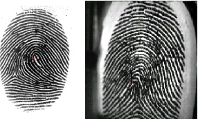
Several fingerprint-matching algorithms align the fingerprint images according to the centre point, called the core. This is also referred as image registration. The image registration using core point provides us the invariance with respect to x, y displacement i.e. translation invariance. For the fingerprints that do not contain core, the core is usually associated with the point of maximum ridgeline curvature. In the proposed algorithm a point of most curvature in a fingerprint image has been detected and considered as a reference (core) point. A typical core point detected fingerprint image is shown in Figure 1. A properly core point located fingerprint image has been considered for registration.Figure 1 Typical core point location in fingerprint image
As we go away from the core point there is little variations in the fingerprint ridge pattern, on the contrary as we traverse towards core point it could be easily noted that the variations in ridge flow are much more. In this algorithm the area around core point has been used as the area of interest for determining the orientation feature. An image of size 100 × 100 pixels around the core point has been cropped as shown in Figure 2.
Figure 2 Cropped fingerprint around the core point
The images in which the core point is located less than 50 pixels away from the image border were rejected for training and testing. The smoothing of cropped fingerprint image is carried out using a low pass filter, which helps in minimizing the effect of noise in gradient computation.
For the computation of orientation field the cropped fingerprint image is typically divided into number of non-overlapping blocks and an orientation representative of the ridges in the block is assigned to the block based on analysis of gray scale gradients in the block. The block size to be selected depends on the inter-ridge distance i.e. it should include at least one ridge and one valley in a block. The block orientation could be determined from the pixel gradient orientations based on averaging, voting or optimization. A fingerprint image and its orientation field have been shown in Figure 3.
Figure 3 Fingerprint image and its orientation field The orientation field of a fingerprint is given by,
(1)
Where,
(2)
Volume 3, Issue 3, March 2014
Page 206
w is the size of a block.Gx and Gy are the gradient magnitudes in x and y directions respectively.
The gradient magnitudes have been computed using Sobel gradient operators. A fingerprint image and its orientation image have been shown in Figure 4.
Figure 4 Fingerprint image and its orientation image
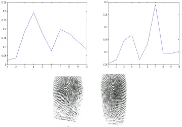
The variance is a measure of energy and this has been used as novel method for deriving the texture features from Gabor filtered images. It could be easily observed that there are substantial discriminating variations in orientation in a fingerprint image (see Figure 5). The variance of orientation is been used as feature vector. The test and trainee images are matched using the L2 norm.
Figure 5 Variance features & corresponding fingerprints
4.
EXPERIMENTAL
RESULTS
The experimental has been carried out on two different databases made available by University of Bologna [8] and the FVC 2002 [9]. The FVC2002 database consists of DB1, DB2, and DB3. The images were acquired under the same conditions: DB1 and DB2 with two large area FTIR optical scanners (388 × 374 pixels, 500 dpi and 560 × 296 pixels, 569 dpi respectively). In our experimentation DB1_a and DB1_b have been used. A part of complete database provided by University of Bologna has been used in the experimentation. The images in this database were captured from capacitive scanner (specifications).
The performance of the algorithm has been evaluated using the Receiver Operating Characteristics (ROC). This consists of a measure of false acceptance rate (FAR) and the false rejection rate (FRR) at various thresholds. Alternately the Genuine acceptance rate (1-FRR) and FAR may be measured at different thresholds. A genuine matching score is obtained when two feature vectors of the same individual are compared and an imposter matching score is obtained when feature vectors of two different individuals are compared. A single template per subject has been considered for experimentation.
Volume 3, Issue 3, March 2014
Page 207
1. N is the number of subjects with 8 fingerprints each.2. Total fingerprint images are T = 8xN.
3. Total trials carried out for finding true claims and imposter claims are Nx(T-1), out of which total true claims are Nx7 and imposter claims are (total trials–true claims).
4. False rejection rate = (true claims rejected/total true claims) x 100 and
5. False acceptance rate = (imposter claimed accepted/total imposter claims) x100 6. Genuine acceptance rate=1 – FRR in percentage.
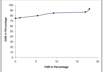
Figure 6 Experimental results for University of Bologna database For every possible combination the algorithm has been tested for computation of FAR and FRR.
University of Bologna database consists of images of 20 subjects with 8 images of each subject. Total 20×8=160 images are present. FAR and GAR at various values of thresholds. The genuine acceptance rate reported 96.33 percent at 11.3 percent FAR and 78 percent for 0.17 percent FAR. As compared to the fingerprint images from FVC2002 database fingerprint images of University of Bologna database are of good quality by means of amount of rotation in claimed fingerprint and average gray level.
Db1_a and Db1_b databases are taken from FVC2002. Db1_a and Db1_b consist of total 800 and 80 fingerprint images respectively. For experimentation 105 subjects with 8 fingerprints of each out of 840 fingerprint images from both the databases have been used. For a single threshold total trials carried out for computations of FAR and FRR were 105x (840-1) = 88095. Results are reported for various thresholds on FVC2002 databases.
Figure 7 Experimental results for FVC2002 database
5.
CONCLUSION
The proposed orientation feature, produce the discrimination between the fingerprints of different persons. The proposed method for estimating the amount of rotation in a fingerprint image is an efficient way, which takes only few computations. The proposed algorithm produce better results at lower and higher values of FAR as compared to minutiae based algorithms. As the algorithm takes fewer computations, it could be implemented using the real time processor.
References
[1] Grasselli A., “On the Automatic Classification of Fingerprints,” in Methodologies of Pattern Recognition, S. Watanabe (Ed.), Academic, New York, 1969.
Volume 3, Issue 3, March 2014
Page 208
[3] Mohammad Sadegh Helfroush and Mohsen Mohammadpour, “An Image-Based Fingerprint Verification System,” International Science and Technology Transactions of Control Engineering - Theory and Applications, Vol.1, No.1 (2) ISSN 1913-8784, June2010, pp 10-13.
[4] A. K. Jain, S. Prabhakar, L. Hong, S. Pankhanti, “Filterbank-based fingerprint matching,” IEEE Transaction on Image Processing, Vol. 9 no. 5, pp. 846-859, 2000.
[5] A. K. Jain, A. Ross, S. Prabhakar, “Fingerprint matching using minutiae and texture features,” in Proceedings of International Conference on Image Processing (ICIP), The Ssaloniki, Greece, pp 282-285, 2001.
[6] Chih-Jen Lee and Sheng-De Wang, “Fingerprint feature extraction using Gabor filters,” Electronic Letter, Vol. 35, no. 4, February 1999.
[7] Arun Ross, Anil Jain, James Reisman, “A Hybrid fingerprint matcher,” Pattern Recognition, Vol. 36, pp 1661-1673, 2003.
[8] Database was available on www.bias.csr.unibo.it/fvc2000/download.asp
[9] Maio D., Maltoni D., Chappelli R., Wayman J. L., and Jain A. K., “FVC2002: Second Fingerprint Verification Competition,” in Proc. Int. Conf. On Pattern Recognition (16th), vol. 3, pp 811 – 814, 2002.
AUTHOR