aptamer-based biosensors
Tobias Reinecke1, Johanna-Gabriela Walter2, Tim Kobelt1, André Ahrens1, Thomas Scheper2, and Stefan Zimmermann1
1Leibniz Universität Hannover, Institute of Electrical Engineering and Measurement Technology,
Department of Sensors and Measurement Technology, Appelstr. 9A, 30167 Hanover, Germany 2Institute of Technical Chemistry, Leibniz Universität Hannover, Callinstr. 5, 30167 Hanover, Germany
Correspondence:Tobias Reinecke ([email protected])
Received: 29 September 2017 – Revised: 6 January 2018 – Accepted: 9 January 2018 – Published: 23 February 2018
Abstract. Split-ring resonators are electrical circuits, which enable highly sensitive readout of split capacity changes via a measurement of the shift in the resonance frequency. Thus, functionalization of the split allows the development of biosensors, where selective molecular binding causes a change in permittivity and therefore a change in split capacity. In this work, we present a novel approach using transmission line theory to describe the dependency between permittivity of the sample and resonance frequency. This theory allows the identification of all relevant parameters of a split-ring resonator and thus a target-oriented optimization process. Hereby all setup optimizations are verified with measurements. Subsequently, the split of a resonator is functionalized with aptamers and the sensor response is investigated. This preliminary experiment shows that introducing the target protein results in a shift in the resonance frequency caused by a permittivity change due to aptamer-mediated protein binding, which allows selective detection of the target protein.
1 Introduction
Split-ring resonators originate from the field of metamateri-als, as they can exhibit effects like negative permittivity and permeability (Smith et al., 2000). However, in recent years, there is an increasing use of split-ring resonators in sensor and measuring technology, as they allow highly sensitive de-tection of changes in the polarizability (permittivity) of a ma-terial via the detection of a shift in the resonance frequency. Split-ring resonators are employed in a broad field of appli-cations (Schueler et al., 2012). There are systems described in literature, e.g., for dielectric characterization of liquids (Ebrahimi et al., 2014) or analysis of organic tissues (Puentes et al., 2011). Furthermore, they are found useful for measur-ing physical values like distance and rotation (Naqui et al., 2011). Another field of application is material testing for the detection of cracks in metal (Albishi and Ramahi, 2014).
Additionally, there are already some biosensors based on split-ring resonators described in literature. In Lee and Yook (2008) they are used for the detection of biotin and streptavidin binding, in Lee et al. (2012) for the
detec-tion of prostate-specific antigen and in Jaruwongrungsee et al. (2015) for the detection of immunoglobulin. Further-more, observation of DNA hybridization is reported in Lee et al. (2010).
However, all described resonator structures differ signif-icantly, e.g., in size, shape and used materials, complicat-ing the comparison of sensor performance. Based on our ini-tial paper (Reinecke et al., 2017), the aim of this work is to present a new theory for the dependency of resonance fre-quency and sample permittivity. Subsequently, this theory is used to perform target-oriented parametric studies to realize a split-ring resonator exhibiting maximum sensitivity. Pre-liminary results of a first aptamer-functionalized split-ring resonator for the label-free detection of C-reactive protein (CRP) are presented.
2 Fundamentals
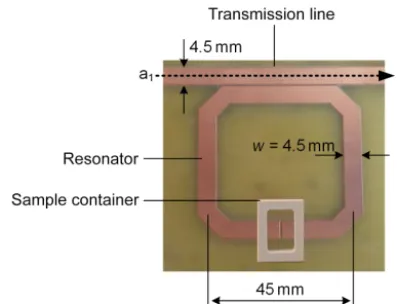
Figure 1.PCB with split-ring resonator.
Figure 2.Transmission measurement of the unloaded split-ring res-onator.
substrate with a ground plane on the backside. The structure on the top layer consists of a transmission line with a width of 4.5 mm resulting in a wave impedance of 50. Further-more, a square resonator structure with a mean edge length of 45 mm is located in a small distance of 300 µm. The edges of the resonator structure are cut off to reduce fringe effects. In a previous work, the square structure was found to be su-perior to a round structure, as it leads to a better coupling between resonator and transmission line, combined with a highQfactor (Reinecke et al., 2016). Opposite to the trans-mission line, there is a split in the resonator structure with a sample container placed on top of it.
The split-ring resonator is characterized via a transmission measurement (S21=b2/a1), i.e., the amplitude ratio of the received waveb2and the transmitted wavea1. TheS21 de-pendent on the frequency for the depicted unloaded resonator (loaded with air respectively) is shown in Fig. 2. Hereby, the resonance frequency is found at the lowestS21value.
Figure 3.CST Microwave Studio simulation of the split-ring res-onator outside resonance(a)and in resonance(b).
The electromagnetic behavior of the resonator can be vi-sualized via FEM (finite element method) simulations as de-picted in Fig. 3. Outside of resonance, the resonator structure is virtually field-free and thus all power is transmitted from transmitter to receiver (a1=b2). However, in resonance, the wave couples into the resonator structure, where a standing wave is formed. Therefore, there is a high field strength in the ring, especially in the split (see Fig. 3b), and thus power transmission from transmitter to receiver is drastically dimin-ished (a1>b2).The resonance frequency partly depends on the circumference of the resonator, while a bigger circumfer-ence leads to a lower resonance frequency and, furthermore, the resonance frequency is determined by the capacity of the split.
3 New theory for the relation between relative sample permittivity and resonance frequency
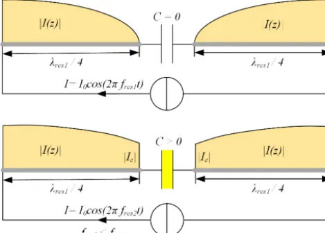
tech-Figure 4. Current distribution in the resonator structure in reso-nance for a hypothetical split capacityC=0 (top) andC >0 (bot-tom).
nology (Rudge et al., 1983; Huang and Boyle, 2008). How-ever, the commonly used assumptions for describing this phenomenon are only valid for very small extensions of the electrical length and thus cannot be applied for the descrip-tion of a split-ring resonator. Therefore, a new theory based on transmission line theory to describe the relation between relative sample permittivity and resonance frequency is pre-sented in the following.
The relative permittivity is generally a complex valueεr=
εr0−j εr00. The real part of the relative permittivityε0ris a mea-sure for the polarizability of a material and the imaginary part
εr00a measure for dielectric or conductive losses. The follow-ing theory only considers the frequency shift due to a change in the polarizability of the material (ε0r). However, the influ-ence of dielectric losses is accounted for by using the natu-ral frequency (undamped resonator) instead of the measured resonance frequency. The natural frequency is attained by di-viding the resonance frequency by
√
1−D2, whereDis the measured damping ratio of the resonance peak.
Figure 4 (top) shows the unwrapped resonator structure. The split is modeled as a capacity and the coupling between transmission line and resonator structure is modeled as a cur-rent source. At first, a hypothetical case where the split ca-pacity isC=0 is considered. Here, the boundary condition for the current distribution of the standing wave on the res-onator isI=0 at the end of the open sides of the line (posi-tion of the split). Therefore, the half-wave length of the res-onance frequency equals the circumference of the resonator, i.e.,λres1/2=180 mm, and thus the resonance wavelength is
λres1=360 mm.
However, when adding a split capacityC >0 to the open end of the line, the capacitor is charged with a chargeQand the current at the split becomes|I| = |Ie|>0, with|Ie| ∼Q or |Ie| ∼C respectively. As shown in Fig. 5, the capacity
Figure 5.A capacitive load leads to an extension of the electrical length of the resonator.
Figure 6.Cross section of the split capacity.
at the end of the line acts like an additional piece of line with a length of1l, leading to an extension of the electri-cal length of the resonator (analogue to the electrielectri-cal exten-sion of dipole antennas through hat capacities). Therefore, the resonance wavelength increases (λres2=λres1+41l) and the resonance frequency decreases tofres2=v/λres2 respec-tively. Herevis the propagation velocity of the electromag-netic wave.
A quantitative description of the dependency between the extension of the electrical length1land the split capacityC
can be found by calculating the input impedance of a trans-mission line of lengthl0 terminated with the split capacity and equalizing this impedance with the input impedance of an open line (stub) of lengthλres2.
According to transmission line theory, the input impedance of a transmission line with a length l0 ter-minated with an impedanceZ2 at the resonance frequency
fres2is
Z1=ZL
Z2+j ZLtan
2π l0 λres2
ZL+j Z2tan
2π l0 λres2
. (1)
Here,ZLis the wave impedance of the resonator structure andZ2is the impedance of the split capacity, i.e.,
Z2= 1
j2π fres2C
Figure 7.Transmission measurement for different mixtures of wa-ter and isopropanol in the sample container.
The electric potential in the center of the split is always
ϕ=0 V, because the open ends of the resonator are always on opposite potential. Therefore, for modulating the split as an equivalent circuit, the cross section depicted in Fig. 6 shows a transmission line connected to ground via three par-allel capacities: the sample-dependent capacity Csample and two parasitic capacities above and below the sample capac-ityCair+Csubstrate=Cp.
Then, the split capacityCcan be written as
C=Csample+Cp=Csample, εr=1·ε 0
r, sample+Cp. (3) Here, Csample,εr=1 is the sample capacity for an air-filled split. Combining Eqs. (1), (2) and (3), equalizing the result to the impedance of an open transmission line with length
l1=λres2/4 (resonance case: Zres=0) and using a Taylor approximation yields the desired dependency between the resonance wavelength λres2and the relative sample permit-tivityεr’:1
λres2=2l0 (4)
+
q
4l02+16l0vZL(Cp+Csample, εr=1·ε 0
r, sample). Here v is the propagation velocity, which only depends on the speed of lightc0and the effective permittivityεeff, which in this term is a superposition of the relative substrate per-mittivity (εr,FR4=4.1) and the relative permittivity of air (εr ,Air=1):
v=√c0
εeff
. (5)
1Detailed calculation including single steps can be found in the
Supplement.
Figure 8. Validation of theory via measurements of water-isopropanol mixtures.
Note that whenC=0, Eq. (4) becomes
λres2 4 =
λres1
4 =l0. (6)
This result supports the theory, because, as was already shown in Fig. 4, for this hypothetical case, the half-wave length of the resonance frequency must be equal to the cir-cumference of the resonator.
To further test Eq. (4) for plausibility, mixtures of iso-propanol (εr,i0 =9) with an increasing content of deionized water (εr,w0 =80) are filled in the sample container, leading to a sample with increasing relative permittivity. The rela-tive permittivity dependent on the mixture ratio can be found using Akerlof (1932), Sihvola (2000) and Lou et al. (1997).
It can be seen in Fig. 7 that increasing the real part of the relative permittivity of the sampleεr, sample leads to an in-crease in resonance wavelengthλres2, as predicted by Eq. (4), and thus to a shift in resonance frequency towards lower fre-quencies. Observing the peak width dependent on the imag-inary part of the relative permittivity reveals that an increase in dielectric losses or conductivity leads to peak-broadening, i.e., lowering of the quality factor or increase in damping of the resonator.
With the data from Fig. 7, Eq. (4) is verified and the un-known capacitiesCpandCsample,εr=1are determined.
There-fore, the function is fitted to the measured data. As a linear fit delivers better results as a fit to a square root, Eq. (4) is squared to
(λres2−2l0)2=4l20+16l0vZLCp +16l0vZLCsample,εr=1·ε
0
r, sample. (7)
Figure 9.Dependency between the resonance wavelength and the real part of the relative permittivity.
sample ε0r, sample. The lengthl0 is the half circumference of the used resonator structure (here, l0=90 mm). To elimi-nate the influence of damping on the resonance frequency, the resonance wavelength is calculated toλres2=f0√c0εeffwith
fres=f0 √
1−D2.
A linear correlation with a Pearson’s coefficient of R=
0.999 for the dependency between (λres2–2l0)2and the real part of the relative sample permittivity can be derived, con-firming the theoretical considerations. Determination ofCp and Csample,εr=1 is achieved via equating coefficients with
the linear fit to
Cp=
a−4l02
16l0vZL
=2.792 pF and
Csample,εr=1=
b
16l0vZL
=0.213 pF. (8)
Therefore, all variables included in Eq. (4) are determined and calculating the resonance frequency for a given sample permittivity is possible. Concluding, Fig. 9 shows the depen-dency between the resonance wavelength and the real part of the relative permittivity.
These results enable a target-oriented optimization pro-cess. From Eq. (4) it can be seen that the sensitivity depends on the split capacity, the wave impedance, the circumference of the resonator structure and the propagation velocity. In the next section, a systematic study of these parameters is per-formed to increase the sensitivity of the setup.
4 Setup optimization
The propagation velocity only depends on the speed of light
c0and the effective permittivityεeff. To increase the sensitiv-ity,vwould have to be increased, which is only possible by
Figure 10.Split-ring resonator with different split capacities.
Figure 11.Measuring an increasing sample permittivity with dif-ferent split capacities.
decreasing the effective permittivity and thus decreasing the relative permittivity of the substrate. Asεr,FR4has already a low value, the propagation velocity is not a parameter with broad potential for optimization. On the other hand, increas-ing the split capacity is more effective which is presented in the following section.
Figure 12.Electrical field in the cross section of the split capacity for a simple split(a)and interdigital structure(b).
fingers have a length2ofl=5 mm, a width ofwf=500 µm and the space between the fingers ofs=500 µm.
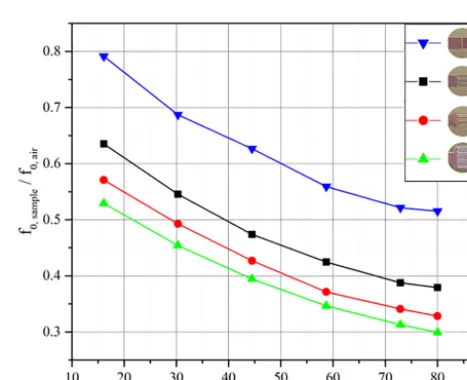
To investigate the effect on the sensitivity, again mixtures of isopropanol and deionized water are measured. The re-sults are shown in Fig. 11. Here, the resonance frequencies are normalized to the resonance frequency of the unloaded resonator.
Increasing the split capacity leads to a significantly in-creased sensitivity. When using a simple split, the relative frequency shift from the unloaded resonator (εr, sample=1) to the resonator loaded with deionized water (εr, sample=80) is 50 %, while the relative frequency shift increases to 70 % when using an interdigital structure with six fingers.
Another advantage of interdigital structures for the realiza-tion of a biosensor becomes apparent by looking at the elec-trical field in the capacity, depicted in Fig. 12. When using a simple split, the penetration depth of the electrical field is relatively high. Therefore, the environment (e.g., permittiv-ity of the sample) has a high influence on the measurement. However, the purpose of a biosensor is to detect binding re-actions on the surface of the split capacity and therefore a low penetration depth is preferable to increase the influence of the binding reaction and decrease the influence of the envi-ronment on the measuring result. Therefore, the six-finger in-terdigital structure is superior to the simple split, as the field concentrates around the fingers, see Fig. 12b.
To further decrease the penetration depth and simultane-ously increase the capacity, the space between the fingers
2Increasing the length of the fingers has a similar effect to
in-creasing the number of fingers. A figure comparing results for
l=5 mm andl=3.5 mm can be found in the Supplement.
Figure 13.Decreasing penetration depth via decreasing the space between the fingers of an interdigital structure.
Figure 14.Split-ring resonator on a 1.4 mm thick FR4 substrate with six-finger interdigital capacity.
of the six-finger structure is gradually decreased froms=
500 µm tos=150 µm in the final optimization step. Smaller spacessbetween the fingers could not be investigated due to technical limitations in the manufacturing process.
Figure 15.Measurement results for unloaded resonators with different wave impedances of the resonator structure:(a)transmission mea-surement;(b)quality factor.
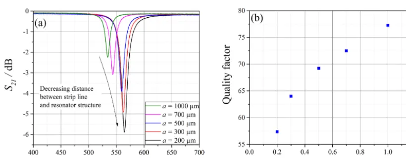
Figure 16.Increasing coupling by decreasing distance between strip line and resonator structure:(a)transmission measurement;(b)quality factor.
guaranteed, as the volume of the sample container is signif-icantly larger than that of the fluid, resulting in higher mea-surement uncertainty at those meamea-surement points.
The results in Fig. 13 show that decreasing the space be-tween the fingers leads to an increased split capacity and thus to an increased sensitivity, as there is a higher shift in reso-nance frequency towards smallers. Furthermore, the pene-tration depth decreases: while there is still a small frequency shift observable for the resonator withs=500 µm, when in-creasing the fluid level from 200 to 250 µL, the signal al-ready saturates at a fluid level of 100 µL for the resonator withs=150 µm.
In the first experiments, we found that using a 3 mm thick FR4 substrate relates to significant fabrication tolerances. Therefore, we chose to carry out all following experiments with split-ring resonators on 1.5 mm thick FR4 substrates. The corresponding split-ring resonator is shown in Fig. 14.
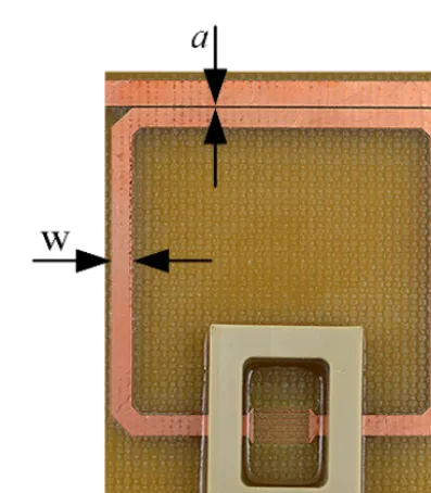
The wave impedance is in inverse proportion to the con-ductor width of the resonator structure (ZL∼1/w). Fig-ure 15 depicts theS21 dependent on the frequency for res-onators with decreasing w and therefore increasing ZL of the square resonator structure. The width of the transmission line is kept constant at 2.4 mm (50on 1.5 mm FR4 sub-strate) for all measurements. As predicted by Eq. (4), an in-creasingZLleads to a decreasing resonance frequency. How-ever, aw <1.5 mm leads deterioration of the coupling be-tween transmission line and resonator structure; i.e., the min-imumS21 becomes smaller. Additionally, the quality factor decreases with increasingZL. Therefore, the optimum width of the resonator structure is found atw≈2.0 mm as the qual-ity factor is not significantly reduced, combined with maxi-mum coupling.
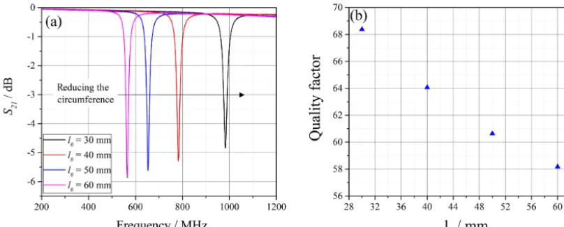
Figure 17.Influence of the circumference of the resonator structure on the resonance frequency:(a)transmission measurement;(b)quality factor.
Figure 18.Final layout of the split-ring resonator.
Figure 19.Optical detection of CRP bound to aptamers.
a=200 µm. Smaller distances could not be investigated due to technical limitations in the manufacturing process.
Figure 16 shows the measured transmission of resonators with differenta. Decreasing the distance leads to better cou-pling but decreases the quality factor of the resonance peak. However, directly contacting transmission line and resonator structure (data not shown) leads to even higher coupling but also to massive peak deformation.
Finally, the circumference (2l0) of the resonator structure influences the sensitivity according to Eq. (4). Furthermore,
Figure 20.S21 with deionized water as sample before and after immobilization of aptamers.
it is possible to adjust the resonance frequency, as shown in Fig. 17. A length of l0=30 mm leads to a resonance fre-quency of almost 1 GHz, while doubling l0 reduces it to 570 MHz. Higher quality factors are found at higher reso-nance frequencies.
Figure 21.S21of control resonator with deionized water as sample before and after exposure to immobilization chemicals.
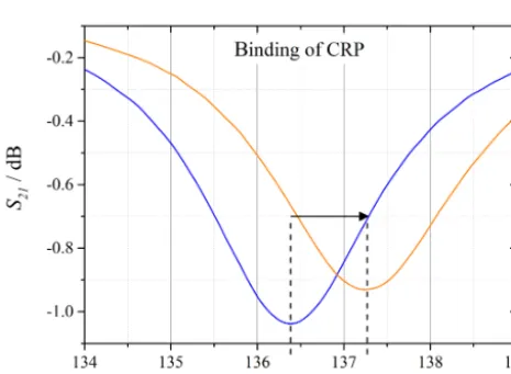
Figure 22. S21 with deionized water as sample before and after binding of CRP.
5 Initial results: aptamer-based detection of C-reactive protein (CRP) with a split-ring resonator
In this section, the split capacity is functionalized with ap-tamers. Aptamers can be considered as artificial alternatives to antibodies, produced via chemical synthesis (Toh et al., 2015). Their in vitro selection process enables the genera-tion of different aptamers selectively binding a huge vari-ety of different target molecules, even toxic or low immuno-genic ones (Mairal et al., 2008). As a first model system, CRP purified from human plasma (Bio-Rad, Puchheim, Ger-many) and corresponding aptamers (sequences derived from Chao-June Huang et al., 2010, and synthesized by BioSpring, Frankfurt, Germany) are purchased from OTC Biotech, San Antonio, USA. In a first step, the aptamers’ ability to se-lectively bind CRP is tested. Therefore, 50 amino-modified
Figure 23.S21 with deionized water as sample before and after exposition to CRP.
aptamers are spotted on a 3-D aldehyde-modified microar-ray slide (PolyAn, Berlin, Germany), similar to the proce-dure described in Heilkenbrinker et al. (2015), and subse-quently exposed to solutions with different concentrations of fluorescence-labeled CRP to perform quantitative measure-ments.
Furthermore, the aptamers are exposed to solutions with different concentrations of fluorescence-labeled bovine serum albumin (BSA) to test the selectivity of the aptamers.
The results in Fig. 19 show that the fluorescence of the small spots where aptamers are immobilized increases when exposed to an increasing concentration of fluorescence-labeled CRP. Therefore, it can be concluded that quantitative measurements of CRP are possible with these aptamers. The test series with fluorescence-labeled BSA shows virtually no response, which leads to the conclusion that the aptamer se-lectively binds CRP.
Similar to the immobilization procedure described in Loo et al. (2014), aptamers are immobilized on the split capac-ity of a split-ring resonator. In parallel, a control resonator is exposed to all chemicals necessary for the immobilization process without finally immobilizing aptamers. In this way it is excluded that the sensor response arises from parasitic ef-fects, e.g., an alteration of the capacity, due to reactions with those chemicals. Furthermore, all measurements are carried out with deionized water in the sample container after per-forming several washing steps. Thus, the influence of the permittivity of the solutions containing aptamers and CRP respectively is eliminated and it is assured that solely bind-ing reactions on the surface of the split capacity are causbind-ing a measuring signal.
the resonance frequency increases after exposure to CRP. This can be caused by adsorption of CRP on the gold sur-face, leading to an increase in split capacity.
However, the presented results show that aptamer-functionalized split-ring resonators can be used as biosen-sors, as the small changes in split capacity due to binding reactions on the gold surface can be detected via the highly sensitive detection of shifts in resonance frequency.
6 Conclusions
In this work, we presented a systematic investigation of a split-ring resonator for application as a biosensor. The pa-rameters responsible for the sensitivity of the setup were de-termined based on a new approach to determine the reso-nance frequency dependent on the relative permittivity of the sample using transmission line theory. Based on these pa-rameters, the resonator structure was optimized and all opti-mizations where verified by measurements. Subsequently, a split-ring resonator was functionalized with aptamers and a selective detection of CRP could be shown. In future work, the immobilization process will be improved to gain higher sensor responses and more efficient blocking of the gold sur-face. Furthermore, the optimal resonance frequency for CRP detection needs to be determined. Finally, quantitative mea-surements will be performed.
Data availability. All relevant data are contained in the paper and the Supplement.
The Supplement related to this article is available online at https://doi.org/10.5194/jsss-7-101-2018-supplement.
Competing interests. The authors declare that they have no con-flict of interest.
cracks in metallic and non-metallic materials using a comple-mentary split-ring resonator, Sensors (Basel, Switzerland), 14, 19354–19370, https://doi.org/10.3390/s141019354, 2014. Ebrahimi, A., Withayachumnankul, W., Al-Sarawi, S., and Abbott,
D.: High-Sensitivity Metamaterial-Inspired Sensor for Microflu-idic Dielectric Characterization, IEEE Sensors J., 14, 1345– 1351, https://doi.org/10.1109/JSEN.2013.2295312, 2014. Heilkenbrinker, A., Reinemann, C., Stoltenburg, R., Walter,
J.-G., Jochums, A., Stahl, F., Zimmermann, S., Strehlitz, B., and Scheper, T.: Identification of the target bind-ing site of ethanolamine-bindbind-ing aptamers and its exploita-tion for ethanolamine detecexploita-tion, Anal. Chem., 87, 677–685, https://doi.org/10.1021/ac5034819, 2015.
Huang, Y. and Boyle, K.: Antennas, From theory to practice, Chich-ester, Wiley, 2008.
Huang, C.-J., Lin, H.-I., Shiesh, S.-C., and Lee, G.-B.: Integrated microfluidic system for rapid screening of CRP aptamers uti-lizing systematic evolution of ligands by exponential enrich-ment (SELEX), Biosensors and Bioelectronics, 25, 1761–1766, https://doi.org/10.1016/j.bios.2009.12.029, 2010.
Jaruwongrungsee, K., Waiwijit, U., Withayachumnankul, W., Maturos, T., Phokaratkul, D., Tuantranont, A., Wlo-darski, W., Martucci, A., and Wisitsoraat, A.: Microfluidic-based Split-Ring-Resonator Sensor for Real-time and Label-free Biosensing, Proc. Eng., 120, 163–166, https://doi.org/10.1016/j.proeng.2015.08.595, 2015.
Lee, H.-J. and Yook, J.-G.: Biosensing using split-ring res-onators at microwave regime, Appl. Phys. Lett., 92, 254103, https://doi.org/10.1063/1.2946656, 2008.
Lee, H.-J., Lee, H.-S., Yoo, K.-H., and Yook, J.-G.: DNA sensing using split-ring resonator alone at microwave regime, J. Appl. Phys. 108, 014908, https://doi.org/10.1063/1.3459877, 2010. Lee, H.-J., Lee, H., Moon, H.-S., Jang, I.-S., Choi,
J.-S., Yook, J.-G., and Jung, H.-I.: A planar split-ring resonator-based microwave biosensor for label-free detec-tion of biomolecules, Sensor. Actuator. B, 169, 26–31, https://doi.org/10.1016/j.snb.2012.01.044, 2012.
Loo, F.-C., Ng, S.-P., Wu, C.-M. L., and Kong, S. K.: An ap-tasensor using DNA aptamer and white light common-path SPR spectral interferometry to detect cytochrome-c for anti-cancer drug screening, Sensor. Actuator. B, 198, 416–423, https://doi.org/10.1016/j.snb.2014.03.077, 2014.
ganic tissues, edited by: IEEE Staff, 2011 IEEE/MTT-S Interna-tional Microwave Symposium, 2011 IEEE/MTT-S InternaInterna-tional Microwave Symposium – MTT 2011, Baltimore, MD, USA, 5/6/2011–10/6/2011, IEEE Staff, IEEE, 1–4, 2011.
Reinecke, T., Ahrens, S., and Zimmermann, S.: Biosensorplattform auf Basis von Split-Ring Resonatoren, edited by: Zimmermann, S., 30, Messtechnisches Symposium, Berlin: De Gruyter, De Gruyter Oldenbourg, 2016.
Reinecke, T., Kobelt, T., Ahrens, A., Zimmermann, S., Scheper, T., and Walter, J.-G. (Eds.): A3.4 – Biosensor based on a split-ring resonator, AMA Service GmbH, Von-Münchhausen-Str. 49, 31515 Wunstorf, Germany, 6 pp., AMA Association for Sensors and Measurement, Sophie-Charlotten-Str. 15, 9 Berlin, Germany, 2017.
Schultz, S.: Composite medium with simultaneously negative permeability and permittivity, Phys. Rev. Lett., 84, 4184–4187, https://doi.org/10.1103/PhysRevLett.84.4184, 2000.