Journal of Engineering Sciences, Volume 6, Issue 1 (2019), pp. E 33–E 38 E 33 JOURNAL OF ENGINEERING SCIENCES
ЖУРНАЛ ІНЖЕНЕРНИХ НАУК
ЖУРНАЛ ИНЖЕНЕРНЫХ НАУК
Web site: http://jes.sumdu.edu.ua
DOI: 10.21272/jes.2019.6(1).e6 Volume 6, Issue 1 (2019)
UDC 536.2:697.1
Dynamic Simulation of Heat Transfer through External Building Constructions
Pitel J.1, Khovanskyi S.2, Pavlenko I.2, Mizakova J.1*1
Faculty of Manufacturing Technologies with a seat in Presov, Technical University of Kosice, 1 Bayerova St., 080 01 Presov, Slovakia;
2
Faculty of Technical Systems and Energy Efficient Technologies, Sumy State University, 2 Rymskogo-Korsakova St., 40007 Sumy, Ukraine
Article info:
Paper received:
The final version of the paper received: Paper accepted online:
January 20, 2019 April 24, 2019 April 29, 2019
*
Corresponding Author’s Address:
[email protected]
Abstract. In the paper, some approaches to dynamic modeling of heat transfer through external building construc-tions are presented. The model of heat transfer dynamics through a wall was designed on the base of mathematical describing of an energy balance for the elementary layer of a plane wall. The wall was considered as a continuum with continuously distributed thermal resistance and capacity. Based on the designed analytical mathematical model, a simulation model in MATLAB/Simulink environment was developed. These dynamic models of heat transfer through the wall with real materials parameters and also through the window with real thermal parameters were simu-lated and some simulation results are presented in the paper.
Keywords: dynamic modeling, mathematical model, heat transfer.
1
Introduction
Heating, cooling, and lighting are the primary energy consumers in buildings, but heating is predominant [1]. To improve energy efficiency and reduce energy con-sumption, it is highly important to obtain patterns of en-ergy use, climatic conditions, heat transfer characteristics, and ventilation requirements.
Heating models can be installed on the basis of system identification and statistical methods to assess the energy consumption of buildings by combining existing data. Since the interior of the building is not always meet the requirements of comfort, the reaction of the building should be corrected through the heating or air-conditioning systems that act as controlled heat or cold sources [2].
Due to a high number of insulating materials are wide-ly used in new construction and modern building enve-lope has more complicated internal and external struc-tures [3], the problem of dynamic simulation of heat transfer through external building constructions is the urgent scientific problem.
Previously developed simplified models are able to de-scribe existing building systems with the aim of predic-tion for air-condipredic-tioning system optimal control [4]. However, these models need to be supplemented by de-tailed physical models of heat transfer.
2
Literature Review
A number of research works are aimed at ensuring the precise dynamic simulation of heat transfer through ex-ternal building constructions. Particularly, the paper [5] presents the analysis of energy demand in residential buildings for different climates by means of dynamic simulation.
The paper [6] presents a solution of the problem of heat transfer through walls for energy independent build-ing applications in the form of an optimized, thermally controlled storage using phase change materials integrat-ed to building walls.
Thermal dynamic modeling and simulation of a heat-ing system for a multi-zone office buildheat-ing equipped with demand controlled ventilation using MATLAB/Simulink is presented in the paper [7].
Using the CFD methods for numerical simulation of the heat and mass transfer processes is proposed in the articles [8, 9].
Modeling of conduction transfer functions for typical thermal bridges identified in BIM data is proposed in the paper [10].
E 34 MECHANICAL ENGINEERING: Computational Mechanics
3
Research Methodology
3.1
Mathematical description of heat transfer
dynamics through a wall
For the design of the mathematical model of heat transfer dynamics through the wall, we have considered a single-layered plane wall, where the wall has been con-sidered as a continuum with continuously distributed thermal resistance and capacity. We have chosen elemen-tary layer with following parameters, m (Figure 1):
dy – thickness of an elementary layer in a plane wall; di – thickness of the whole single-layered plane wall;
y – a distance of elementary layer from the heated sur-face.
di y dy
F1 F F +dF F2
Figure 1 – Single-layered plane wall
Let’s others variable has been used for mathematical description: F1 – heat flow supplied into the heated wall surface, W; F2– heat flow taken away from the cooled wall surface, W; F – heat flow inputs into unit surface of layer dy, and heat flow (F + dF) outputs from it, W.
Material parameters of a single-layered plane wall which have been used for mathematical description:
c – specific heat capacity, J/(kgK); – volume weight, kg/m3; – heat conductivity of wall material, W/(mK).
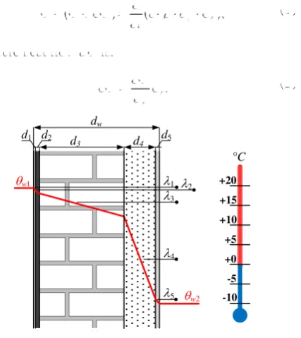
If a wall of the real building is considered, which con-sists of several layers (Figure 2) with various parameters of each material, the materials parameters and the tem-peratures on both sides of such wall can be denote as follows: w1 – temperature of the heated wall surface, K; w2 – temperature of the cooled wall surface, K; w –
temperature of elementary layer, K; di– i-layer thickness,
m; λi – heat conductivity of i-layer material, W/(mK).
The parameters of the multi-layered wall are calculat-ed as follows: Ri = di/λi – thermal resistance of i-layer
with thickness di, Km2/W; dw =
n i i d 1
– thickness of
multi-layered wall, which consists from layers with thickness di, m; R =
n i i R 1
– thermal resistance of
multi-layered wall, which consists from layers with thermal
resistance Ri, Km2/W; U = 1/R – heat transfer coefficient,
W/(m2K).
According to [12] the heat energy does not originate either does not dissolve in considering an elementary layer of the wall. Then the difference of input heat and output heat in the layer has to be equal to the time varia-tion of the energy in a layer.
Let’s c is a specific heat capacity and is a volume weight of the wall material, then:
d
c dy
,t w
F F
F (1)
where heat flow dF is:
. d d y y F F (2) dw
d3 d4
w1 w2 1 3 4 5 d1 2
d2 d5
°C +20 +15 +10 +5 +0 -5 -10
Figure 2 – Multi-layered plane wall
If specific heat capacity c and volume weight of the used wall material are constant, then:
. t c y w F
(3)
According to Fourier’s law, the heat flow is directly proportional to the temperature gradient
, y w
F (4)
where is the heat conductivity coefficient of the used wall material.
These partial differential equations (3) and (4) with relevant initial and border conditions completely describe non-stationary one-dimensional heat flow. After expres-sion of dependent variables by their values and incre-ments and their conversion to non-dimensional form [13, 14] we have got partial differential equations system of heat transfer dynamics through a wall:
; 0 F t x d c y
x w w
Journal of Engineering Sciences, Volume 6, Issue 1 (2019), pp. E 33–E 38 E 35 This system describes the dependence of
non-dimensional variables xF for heat flows F and xw for
temperatures w, but it still needs to be supplemented by
equations of heat transfer on both sides of the wall sur-faces. In dimensionless form for the indoor surface area it is valid:
2 1
1 1 1,1 1 *
1
1 x xw xa xw h xw
xF F (7)
where x*Ф1 includes also external effects on the heat flow transfer into the wall, xθa2 is the temperature of air warming the wall, κ1 = h1·dw/λ, and h1 is heat transfer coefficient between air and wall surface, W/(m2K).
Similarly, for the outdoor surface area it is valid:
2
2 2 2,2 2 *
2
2 x xw xw xo h xw
xF F (8)
where x*Ф2 includes external conditions of the heat flow transfer from the wall,
x
o is the temperature of air cooling the wall,κ2 = h2·dw/λ, and h2 is heat transfer coef-ficient between the wall surface and air W/(m2K).Using Laplace transform and some substitutions (de-tailed described in [15]) we have got equations:
1
1
2
2
;2 p G p X p G p X p
XF F w (9)
3
1
1
2
,1 p G p X p G p X p
Xw F w (10)
where:
1 ;1
p ch p
G (11)
th ;2 p p p
G (12)
th .3
p p p
G (13)
Then using substitution solved in [15] and substitution
p = Ts·s, we have got transfer functions:
; ) ( 12 24 24 12 24 24 2 2 1 s T s T p p p G s s (14)
; ) ( 12 24 ) ( 6 4 12 24 6 4 2 2 2 2 2 s T s T s T s T p p p p p G s s s s (15)
, ) ( 12 24 5 ) ( 20 120 12 24 5 20 120 2 2 2 2 3 s T s T s T s T p p p p p G s s s s (16)
where Ts = d 2s·ρ·с/λ is constant, which is depended on
wall properties dw and
. · · · 1 1
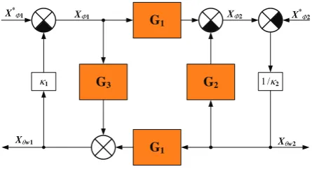
n i i i w n i i w w d d R d R d (17)Based on equations (7)–(10) block diagram of heat transfer dynamics through a wall was designed and it is shown in Figure 3.
1
X*F1
G1
G3 G2
G1
1/2
XF1
Xw1 Xw2
XF2 X*F2
Figure 3 – Block diagram of heat transfer dynamics through a wall
3.2
Simulation model of heat transfer
dynamics
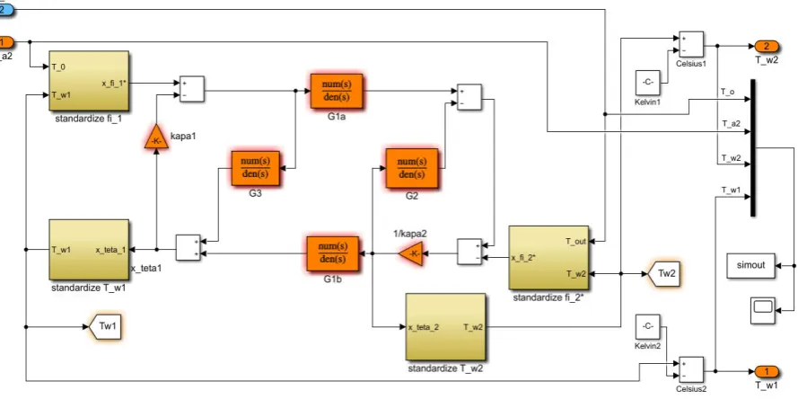
In Figure 4, there is presented dynamic simulation model of heat transfer through a wall developed in MATLAB/Simulink environment. This model was de-signed on the base of the block diagram of heat transfer dynamics through a wall (Figure 3) corresponding to transfer functions (14)–(16) of partial differential equa-tion system (9), (10).
According to (9) and (10), temperature θw1 of the heat-ed wall surface and heat flow Ф2 taken away from cooled wall surface is calculated from heat flow Ф1 supplied into the heated wall surface and from temperature θw2 of the cooled wall surface. Heat flow Ф1 supplied into the heat-ed wall surface is calculatheat-ed using equation (7) with two inputs: temperature θa2 of air warming the wall and tem-perature θw1 of the heated wall surface. The temperature of the cooled wall surface θw2 is calculated using equation (8) and it serves as input into main parts of the model.
The main part of the model is Transfer Fcnblocks
G1a = G1b = G1, G2, and G3, which determine the dynam-ics of the system. Another important part of the model is hierarchical blocks named “standardize”, which serve for calculation of main variables in the model.
4
Results
Using the model in Figure 4 we have simulated heat transfer through the real wall and through the real win-dow, to compare different materials of multi-layered wall, thermal parameters, energy losses, etc.
Firstly, heat transfer through the real wall was simulat-ed (Figure 5) with following real parameters, which have corresponded to parameters measured on typical building wall with thickness dw = 0.520 m, where the wall has
E 36 MECHANICAL ENGINEERING: Computational Mechanics
Figure4 – Dynamic simulation model of heat transfer through a wall
,
R dw
(18)
where R is thermal resistance obtained by formula (for the case of the total number of layers n = 5):
.
5
1
i i
i d R
(19)
Thermal conductivities of the individual wall layers, W/(mK): 1 = 0.70, 2 = 0.03, 3 = 0.52, 4 = 0.04, and 5 = 0.87.
So, thermal conductivity of the simulated multi-layered wall is = 0.15 W/(mK).
Outdoor temperature o has been simulated as a sine
wave with period 86 400 s (i. e. 24 hours), and amplitude 5 °C. The temperature of heating water b1 has been
50 °C.
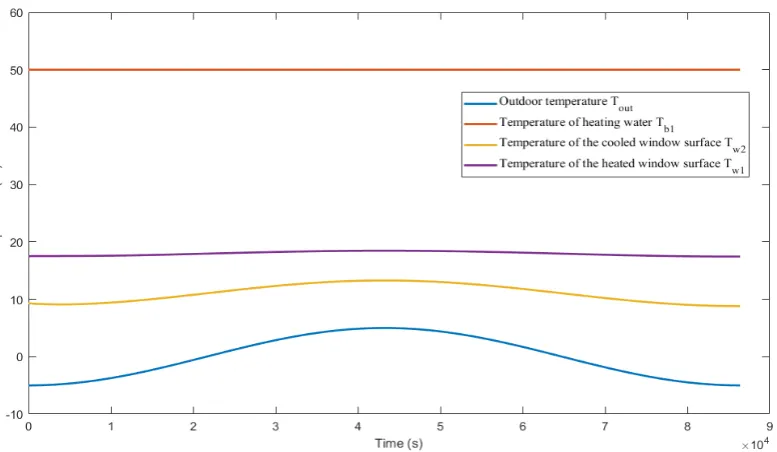
Next, heat transfer through the real wall was simulated (Figure 6) with the following real parameters: thermal resistance R = 1 Km2/W, dw = 0.030 m. Outdoor
temper-ature o has been simulated again as a sine wave with
period 86 400 s (i. e. 24 hours) and amplitude 5 °C. The temperature of heating water b1 has been 50 °C.
Journal of Engineering Sciences, Volume 6, Issue 1 (2019), pp. E 33–E 38 E 37
Figure 6 – Simulation results of heat transfer through the real window: temperature of the heated window surface θw1 (Tw1), and temperature of the cooled window surface θw2 (Tw2)
5
Conclusions
To summarize, the described mathematical model of heat transfer dynamics through a plane wall has led to the system of partial differential equations which second-order transfer functions were derived. Model parameters of single-layered and multi-layered plain walls were also described in the paper. Based on the designed analytical model of heat transfer through a wall, a dynamic simula-tion model in MATLAB/Simulink environment was de-veloped. This model has been tested for different real wall material parameters, for example, a brick wall, insu-lated wall, etc. The tested model was also used for simu-lation of heat transfer through the real window.
Comparison of simulation results in Figures 5, 6 shows that the temperature of the heated wall surface is higher than the temperature of the heated window surface. Con-versely, the temperature of the cooled wall surface is lower than the temperature of the cooled window surface. It shows that heat losses through the window with worse thermal properties are higher than through the wall with better thermal properties. So, the achieved simulation results have confirmed the right approach to model de-sign.
From the point of view of model dynamics, it can be stated that the dynamic change in the outdoor temperature had an impact especially on the temperature of the cooled wall or window surface. This impact is with time delay given by system time constant. The achieved simulation results are in line with theoretical assumptions.
The designed and tested dynamic model of heat trans-fer through external building constructions is needed for simulation of the heating process control based on out-door temperature compensation. So in the future work, this model will be implemented into a dynamic simula-tion model of the heating system containing model of heating body and a model of heating curves.
6
Acknowledgments
This work was supported by the Slovak Research and Development Agency under the contract No. APVV-15-0602.
The achieved results were partially supported by the Ministry of Education and Science of Ukraine under the research project No. 0117U003931.
References
1. Perera, D. W. U., Pfeiffer, C. F., & Skeie, N.-O. (2014). Modelling the heat dynamics of a residential building unit: Application to Norwegian buildings. Modeling, Identification and Control, Vol. 35(1), pp. 43–57, doi: 10.4173/mic.2014.1.4.
2. Missoum, A., Elmir, M., Bouanini, M., & Draoui, B. (2016). Numerical simulation of heat transfer through the building facades of buildings located in the city of Bechar. International Journal of Multiphysics, Vol. 10(4), pp. 441–450.
3. Gao, Y., Roux, J. J., & Zhao, L. H. (2007). A low-order thermal bridge dynamic model for building simulation. Proceedings: Building Simulation, pp. 281–286.
E 38 MECHANICAL ENGINEERING: Computational Mechanics
5. Bianco, V., Rosa, M., Scarpa, F., & Tagliafico, L. A. (2016). Analysis of energy demand in residential buildings for different climates by means of dynamic simulation. International Journal of Ambient Energy, Vol. 37(2), pp. 108–120, doi: 10.1080/01430750.2014.907207.
6. Wegmueller, R., Magnin, G., Robadey, J., & Niederhauser, E.-L. (2018). Controlled active thermal storage in smart PCM walls for energy independent building applications. IEEE 5th International Conference on Renewable Energy: Generation and Appli-cations, 17703462, doi: 10.1109/ICREGA.2018.8337575.
7. Behravan, A., Obermaisser, R., & Nasari, A. (2017). Thermal dynamic modeling and simulation of a heating system for a multi-zone office building equipped with demand controlled ventilation using MATLAB/Simulink. IEEE International Conference on Circuits, System and Simulation, pp. 103–108, doi: 10.1109/CIRSYSSIM.2017.8023191.
8. Svoboda, Z., & Kubr, M. (2011). Numerical simulation of heat transfer through hollow bricks in the vertical direction. Journal of Building Physics, Vol. 34(4), pp. 325–350, doi: 10.1177/1744259110388266.
9. Varukha, D. A., Smirnov V. А., Edl M., Demianenko M. M., Yukhymenko M. P., Pavlenko I. V., & Liaposhchenko O. O. (2018). Simulation of separation and air classification processes of aerodisperse systems in the shelving device. Journal of Engi-neering Sciences, Vol. 5(1), pp. F5–F9, doi: 10.21272/jes.2018.5(1).f2.
10. Narowski, P., Stasierski, J., & Wereszczynski, P. (2011). Modelling of conduction transfer functions for typical thermal bridges identified in BIM data. Proceedings of Building Simulation 2011: 12th Conference of International Building Performance Simu-lation Association, Vol. 12, pp. 1320–1327.
11. Veken, J., Saelens, D., Verbeek, G., & Hens. H. (2004). Comparison of steady-state and dynamic building energy simulation programs. Buildings, Vol. IX, pp. 1-11
12. Cermak, J., Peterka, V., & Zavorka, J. (1968). Dynamika Regulovaných Soustav v Tepelné Energetice a Chemii. Academia, Pra-ha, Czech Republic [in Czech].
13. Piteľ, J. (2007). Matematický model prestupu tepla stenou pre simuláciu riadenia procesu vykurovania. Acta Metallurgica Slovaca, Vol. 13(3), pp. 296-300 [in Slovak].
14. Mizakova, J., & Piteľ, J. (2017). An analytical dynamic model of heat transfer from the heating body to the heated room.
MATEC Web of Conferences, Vol. 125, pp. 1–5.
15. Mizakova, J., Piteľ, J., & Hrehova, S. (2014). Some simulation results of heat transfer through the wall model. International Journal of Mathematical Models and Methods in Applied Sciences, Vol. 8(1), pp. 1–8.
Динамічне моделювання теплообміну через зовнішні будівельні конструкції
Пітель Я.1, Хованський С.2, Павленко І.2, Міжакова Я.11 Факультет виробничих технологій у м. Прешов, Технічний університет м. Кошице,
вул. Баєрова, 1, 080 01, м. Прешов, Словаччина;
2 Факультет технічних систем та енергоефективних технологій, Сумський державний університет,
вул. Римського-Корсакова, 2, 40007, м. Суми, Україна
Анотація. У статті представлені теоретичний і числовий підходи до динамічного моделювання
теплообміну через зовнішні будівельні конструкції. У результаті розроблено модель динаміки теплопередачі
через стіну на основі математичного моделювання енергетичного балансу елементарного шару плоскої стінки. Стіна розглядалась як суцільне середовище з безперервно розподіленим тепловим опором і ємністю.
На основі розробленого аналітичного підходу, що реалізує запропоновану математичну модель, розроблено імітаційну модель із застосуванням середовища MATLAB/Simulink. Продемонстровано динамічну модель
теплопередачі через стіну з параметрами реальних матеріалів, а також через вікно з реальними тепловими параметрами. Результати моделювання представлені графічно.