36 | P a g e
STUDY OF WIND ANALYSIS OF MULTI-STORY
COMPOSITE STRUCTURE FOR PLAN
IRREGULARITY
Shaikh Muffassir ¹, L.G. Kalurkar ²
¹PG Student, Structural Engineering, Department of Civil Engineering
J.N.E.C, Aurangabad, (India)
²Assistant Professor, Department of Civil Engineering,
J.N.E.C, Aurangabad, (India)
ABSTRACT
ETABS 2015 (Extended three dimensional analysis of building system) is the tool to analyses the multi story
structure, for the system of forces, Earthquake analysis, Time history analysis, and Wind analysis. In this case
study the effect of wind on multi story composite structure for plan irregularity is observed. In addition, the
effect of shape on wind analysis is also discussed. In this study the comparison of impact of wind for Square,
Rectangular, U-shape, and H-shape building structure is presented. The post analysis consist typical
characteristic comparison related to storey displacement, storey drift, time period, base reaction, etc. The
categorization of structure as Class-B, Class-C of wind code consideration for different height is used for
modelling of structure. Modelling of as category-2 is taken constant to compare the result. This study of
composite structure for plan irregularity concludes that which shape is more dominant for story displacement,
story drift, time period etc. and also which shape is safer for wind effect.
Keywords
-
ETABS, Composite structure, Multi story building, Plan Irregularity, Wind Analysis.
I. INTRODUCTION
1.1 General
For design of structure as safe it is important to have knowledge of various types of loads and its effect on
structure. Therefore it is essential to have knowledge of their worst combination to which it may be subjected
during its life span. And also to have knowledge about lateral loads such as earthquake and wind load. The
effect of lateral load is very important to consider for high rise composite structure. In some cases the effect of
wind is found greater than earthquake effect. It depends on the zone factor defined by codes.
Lateral loads due to wind which acting on multi story building can cause shake in the upper stories. This could
be effect caused due to wind at upper stories as the wind intensity is increasing with graduating heights. Thus
the multi-story building also act as a portal frame the moment concentrating at base due to lateral wind forces
are greater. Thus it is important to nullify displacement in lateral direction by appropriate design. The effect of
37 | P a g e
building like Bhurj khalifa have given importance of shape. Similarly plan irregularity of composite structure
have discussed in the case study.
1.2 Literature review
Syed Rehan, S.H. Mahure [1]: Presented the work on analysis and design of (G+15) Stories under the effect of
earthquake and wind for Composite, Steel and RCC structure. The modelling and analysis is done by using
Staad pro. And they compare the result of Composite, RCC and steel building such as story displacement, story
drift and Maximum bending moment and shear forces. They suggest that composite structure is better option
compare to RCC and Steel.
Abhay Guleria [2]: They presented the work on structural analysis of multi story building under the effect of
earthquake for RCC structure for different plan configuration. The modelling and analysis is done by using
ETABS software. And they compare the result of different plan configuration buildings such as story
overturning moment, story shear, story drift and mode shapes.
Jawad Ahmed, H S Vidyadhar [3]: They presented the work on wind analysis of multi story buildings with
different lateral load resisting system for different aspect ratio. The modelling and analysis is done by using
ETABS software and the total forty five models are prepared. They suggest that RC shear wall is better to resist
lateral loads compared to RC double bracing.
Swati D. Ambadkar, Vipul S. Bawner [4]: They presented the analysis of (G+11) multi story building for
different terrain category in significant relation of moment, forces and displacement. The modelling and analysis
is done by using Staad pro. Software. For the analysis basic wind speed are taken 44 m/s, 47m/s, and 50m/s.
They conclude that wind speed increases bending moment values also increases according to category.
1.3 Objective
Based on the analysis and result discussion of above literature the study of this paper consist of work of analysis
of wind on multi story composite buildings for different plan irregularity, study also contributed for analysis the
various effect caused due to wind lateral load like Displacement, Storey drift, Base shear and comparative study.
Also the plan irregularity importance in different heights of structures is discussed.
Parameters of lateral load have greater impact for analysis and to take further assessment to improve structural
behavior like Displacement, Storey drift, Base shear, Column forces, Time period, Overturning moment, Storey
stiffness and Maximum Bending moment of beam.
The different loads have considered to analysis the structure like:
a) Dead load consider from Indian Standard Code of Practice for Design loads (other than Earthquake) for
Buildings and Structures, IS: 875(Part 1)-1987
b) Imposed load consider from Indian Standard Code of Practice for Design loads (other than Earthquake) for
Buildings and Structures, IS: 875(Part 2)-1987
c) Wind load consider from Indian Standard Code of Practice for Design loads (other than Earthquake) for
Buildings and Structures, IS: 875(Part 3)-1987
The intensity of Basic wind speed (Vb), Design wind speed (Vz), based on the Indian standard and parameters in
correlation to these standards have considered in design and provided as a input through ETABS in analysis the
38 | P a g e
By using the following formula the design wind speed is calculated.
Vz = Vb*K1*K2*K3
Where, K1= Probability Factor (Risk Co-efficient)
K2= Terrain, Height and Structure size Factor
K3= Topography Factor
After calculating of design wind speed than calculate the design wind pressure. By using following formula the
design wind pressure is calculated.
Pz = 0.6(Vz)²
Where, Pz = design wind pressure in N/mm² at height z
Vz = Design wind velocity in m/s
For calculating the wind load on individual member such as roof, cladding and walls, it is important to take the
pressure difference between opposite faces. For clad building it is necessary to know the external pressure and
internal pressure. For calculating the wind load on individual member acting normal to member is:
F = (Cpi-Cpe) A*Pz
Where, F = Wind load on individual member in KN
Cpi = Internal pressure coefficient
Cpe = Internal pressure coefficient
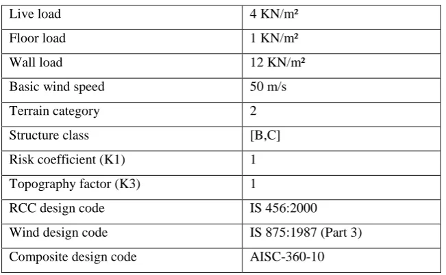
The plan irregularity which is discussed in the study consist of square shape building, rectangular shape
building, H-shape building, U-shape building. Generally these plan irregularity is commonly adopted in
Residential apartment, Hospitals, Educational institute buildings and Commercial buildings. The comparative
data of displacement have discussed in each aspect of design.
For selection of effective load combination in which the ultimate effect regarding all parameter have chosen.
1.2(DL+LL+WindX) have taken as critical combination. Where, WindX is the design wind pressure in
x-direction, which gives the maximum displacement as compared to other direction of wind pressure. For internal
pressure coefficient, the percentage of opening between 5% to 20% is consider. And external pressure
coefficient is computed from IS: 875 (Part 3)-1987 code. For all composite structure cladding is to be consider
and wind load is calculated.
II. SYSTEM DEVELOPMENT
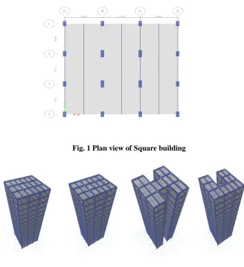
In this Study a multi storied composite structure of 15X15m Plan dimension is considered and the building is
considered as commercial building. The structural properties and dimensions are elaborated below. And also
39 | P a g e
In addition , the composite structure are analyzed for different load combination such as dead load , live load
and wind load as per IS Code 875 (Part 5)-1987. Various specification of loading which are taken is shown in
Table.
Fig. 1 Plan view of Square building
Fig. 2 3D View of Square, Rectangular, H-Shape, U-Shape Buildings
Table 1: Specification of Buildings
Table 2: Material Properties
Plan dimension 15mx15m
(G+5) 7 story 20 m
(G+15) 17 story 50 m
(G+25) 27 story 80 m
Height of each story 3 m
Thickness of deck/slab 0.150 m
Thickness of wall 0.23 m
Grade of concrete M25
Grade of reinforcing steel Fe 500 (HYSD)
Grade of structural steel Fe 345
Density of concrete 25 KN/m³
Density of brick wall 20 KN/m³
40 | P a g e
Table 3: Specification of Loading
Table 4: Specification of (G+5) Composite Buildings
Table 5: Specification of (G+15) Composite Buildings
Composite Section Encased Section
Beam ISWB 550 -
Column up to 9 story
Column-1 600X900 ISWB 600-2
Column-2 450X900 ISMB 600-2
Column-3 450X700 ISWB 550-1
Column from 10 to 17 story
Column-4 450X700 ISWB 550-1
Column-5 350X700 ISMB 550
Column-6 350X650 ISMB 500
Live load 4 KN/m²
Floor load 1 KN/m²
Wall load 12 KN/m²
Basic wind speed 50 m/s
Terrain category 2
Structure class [B,C]
Risk coefficient (K1) 1
Topography factor (K3) 1
RCC design code IS 456:2000
Wind design code IS 875:1987 (Part 3)
Composite design code AISC-360-10
Composite Section Encased Section
Beam ISWB 300 -
Column 1 350X650 ISMB 500
Column 2 300X500 ISMB 350
41 | P a g e
Table 6: Specification of (G+25) Composite Buildings
Composite Section Encased Section
Beam W18X311 -
Column up to 14 story
Column-1 600X1200 W 40X277
Column-2 600X900 W 27X235
Column-3 450X900 W 27X102
Column from 15 to 27 story
Column-4 450X900 W 27X102
Column-5 480X700 W 18X143
Column-6 350X700 W 21X55
III. RESULT AND DISCUSSION
Total twelve numbers of composite structure are modeled using finite element based software ETABS 2015. For
analysis of building, Indian standard code of practice for design loads (other than earthquake for buildings and
structure) IS 875(Part 3):1987 is used for computing basic wind speed (Vb), Internal pressure coefficient (Cpi),
External pressure coefficient (Cpe) and Terrain, height and structure size factor (k2) etc.
42 | P a g e
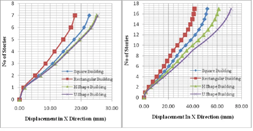
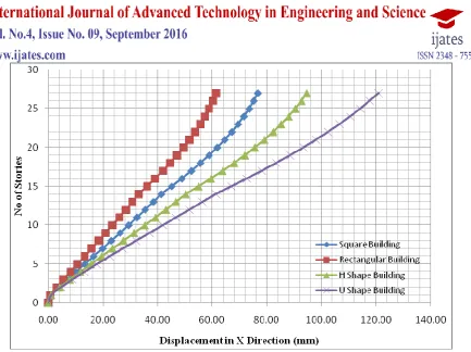
Fig. 5 Story Displacement (For G+25)
The above graph of displacement shows the displacement of (G+5) for plan irregularity similarly shows (G+15)
and (G+25) displacement for different plan configuration. The above Figures suggest that the displacement is
varies with increases in numbers of stories.
3.2. Story Drift
43 | P a g e
Fig. 8 Story Drift (For G+25)
Above Figure 6, 7, 8 shows the story drift for different story such as (G+5),(G+15) and (G+25) for different
shapes of buildings. Story drift increases with increase in height and also story drift is maximum in U shape
building compare to other shape buildings.
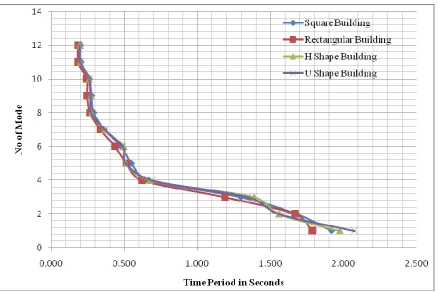
3.3. Time period
44 | P a g e
Fig. 11 Time Period (For G+25)
The time period of (G+5), (G+15) and (G+25) shown in above Figures for different number of modes. The
maximum time period is in U shape building compare to other shapes buildings. Time period are shown for
twelve modes of buildings. Maximum time period are found for mode one in U shape building.
IV. CONCLUSION
This study presented an assessment of wind effect on multi story composite structure for different shapes and
overall analysis result of G+5, G+15, and G+25 shows that
1) Composite structure need to prefer because of the speed in construction due to ease in installation of
structural element.
2) The composite frames are light in weight which reduces the dead load on structure that can reduce the whole
load of building. This reduces dimension of structural member tending to economical aspect.
3) The displacement in U-shape structure increases abruptly as increase in height of story so the U-shape
structure is not preferable in wind prone zone.
4) Overall analysis suggests rectangular structure for along wind or across wind direction is preferable due to
large stiffness and less displacement against wind.
5) In High rise structure the wind pressure is mainly depends on exposed area of building against the wind
intensity So that the exposed area of building need to be altered or needs to deviate to some angle to reduce
45 | P a g e
REFERENCES
[1] Syed Rehan and S.H.Mahure, Study of Seismic and Wind Effect on Multi Storey R.C.C. Steel and
Composite Building, International Journal of Engineering and Innovative Technology (IJEIT), 3(12),
June 2014, 78-83.
[2] Abhay Guleria, Structural Analysis of a Multi-Storeyed Building using ETABS for different Plan
Configurations, International Journal of Engineering Research & Technology (IJERT), 3(5), May 2014,
1481-1487.
[3] Jawad Ahmed, H S Vidyadhar, Wind Analysis and Design of Multi Bay Multi Storey 3D RC Frame,
International Journal of Engineering Research & Technology (IJERT), 2(9), September 2013, 2567-2570.
[4] Swati D.Ambadkar and Vipul S. Bawner, Behavior of Multi story Building under the Effect of Wind
load, International Journal of Applied sciences and Engineering research (IJASER), 1(4), 2012, 656-662.
[5] Dae Kun Kwon, Ahsan Kareem, Wind load factors for dynamically sensitive structures with
uncertainties, Engineering structures (ELSEVIER), 10(3), August 2015, 53-62.
[6] Mark D. Denavit, Jerome F. Hajjar, Analysis and Design of Steel-Concrete Composite Frame Systems ,
ASCE , 12(2), 2014, 2605-2616.
[7] IS: 875(Part 3)-1987, Indian Standard Code of Practice for Design loads (other than Earthquake) for
Buildings and Structures, Bureau of Indian Standards, New Delhi.
[8] IS: 456(2000), Indian Standard Code of Practice for Plan and Reinforcement concrete (Fourth Revisions),
Bureau of Indian Standards (BIS), New Delhi.
[9] IS 808(1989), Dimensions for Hot Rolled Steel Beam, Column, Channel and Angle Sections, Bureau of
Indian Standards (BIS), New Delhi.
[10] IS 11384:1985, Code of Practice for Design of Composite Structure, Bureau of Indian Standards, New
Delhi.
[11] R.P. Johnson, Composite Structures of Steel and Concrete Beams, Slabs, Columns and Frames for
Buildings, Third Edition.
[12] ANSI/AISC 360-10, Specification for Structural Steel Buildings, American Institute of Steel