Niko Hyka Medical University of Tirana, Faculty of Medical Technical Sciences, Tirana, Albania.
Erjon Spahiu University of Tirana, Faculty of Natural Sciences, Department of Physics, Tirana, Albania.
Dafina Xhako University of Tirana, Faculty of Natural Sciences, Department of Physics, Tirana, Albania.
Partizan Malkaj Polytechnic University of Tirana, Faculty of Mathematics Engineering & Physics Engineering, Tirana, Albania.
Theodhor Karaja University of Tirana, Faculty of Natural Sciences, Department of Physics, Tirana, Albania.
In radiotherapy, medical physicists give a major contribution to the safe and effective radiation treatment for patients with cancer. Megavoltage linac photon outputs are determined using the IAEA TRS-398 code of practice or AAPM TG-51 and the results are compared. Beam calibration means: determination of absorbed dose to water per 100 monitor units in a water phantom at reference conditions. The measured dose Dw,Q in water at reference point is a primary parameter for planning the treatment monitor units (MU). Traceability of dose accuracy therefore still depends mainly on the calibration factor of the ion chamber/dosimeter provided by the accredited laboratories. Our data therefore imply that the dosimetry level maintained for clinical use of linear accelerator photon beams are within recommended levels of accuracy, and uncertainties are within reported values. However, in Albania the frequently problem is related to resources with respect to both, qualified teachers and equipment, that are at disposal for teaching and training. The concepts of e-learning methods using different non commercial software, contribute to overcome this problem. In our case, we use an academic education method to practise radiation oncologists and medical physicists for LINAC beam calibration using a virtual simulator program and Matlab. Our group, after some experiences in calculation methods using Matlab, is focused on a PC based program which simulates the required equipment, the measurement set-up, and the measurement itself. All procedures are modelled according to the IAEA Code of Practice, TRS 398.
1. Introduction
After installation of a LINAC, the next procedure is acceptance test and commissioning of linear
accelerator for clinical use (Hyka N. et al. 2013) by medical physicists. Since commissioning
beam data are treated as a reference and ultimately used by treatment planning systems, it is vitally
important that the collected data are of the highest quality to avoid dosimetric and patient
treatment errors that may subsequently lead to a poor radiation outcome. IAEA and AAPM
(Almond PR, et al. 1999), (IAEA 2000, TRS No. 398) reports and other documents which provide
guidelines and recommendations on the proper selection of phantoms and detectors, procedures
for acquiring specific photon and electron beam parameters and methods to reduce measurement
errors under 1%, beam data processing and detector size convolution. TRS 398, provides a
methodology for the determination of absorbed dose to water in the low, medium and high energy
Linac Photon Beam Calibration Using Virtual
Simulator Program
Medicine & Physics
Keywords: Radiotherapy, linac, calibration, beam, protocol, virtual
simulator program.
photon beams, electron beams, proton beams and heavy ion beams used for external radiation
therapy.
2. Materials and Methods
The ranges of radiation qualities covered (IAEA, 2000) in TRS 398 report are given below:
-
Low energy X rays with generating potentials up to 100 kV and HVL (half-value layer) of 3
mm Al (the lower limit is determined by the availability of standards);
-
Medium energy X rays with generating potentials above 80 kV and HVL of 2 mm Al
60Co
gamma radiation;
-
High energy photons generated by electrons with energies in the interval 1–50 MeV, with
TPR20,10 values between 0.50 and 0.84;
-
Electrons in the energy interval 3–50 MeV, with a half-value depth, R
50, between 1 and 20
g/cm2;
-
Protons in the energy interval 50–250 MeV, with a practical range, R
p, between 0.25 and 25
g/cm2;
-
Heavy ions with Z between 2 (He) and 18 (Ar) having a practical range in water, R
p, of 2 to 30
g/cm2 (for carbon ions this corresponds to an energy range of 100 MeV/u to 450 MeV/u,
where u is the atomic mass unit).
Main quantities to measure and calculate during a commissioning procedure or periodically checks
are:
-
D
w,Q(Absorbed dose to water at the reference depth, z
ref, in a water phantom irradiated by a
beam of quality
Q
. The subscript
Q
is omitted when the reference beam quality is
60Co, in gray
(Gy).
-
Eo, Ez
- mean energy of a photon beam at the phantom surface and at depth
z
, respectively, in
MeV.
-
k
i- general correction factor used in the formalism to correct for the effect of the difference in
the value of an influence quantity between the calibration of a dosimeter under reference
conditions in the standards laboratory and the use of the dosimeter in the user facility under
different conditions.
-
k
pol- factor to correct the response of an ionization chamber for the effect of a change in
polarity of the polarizing voltage applied to the chamber.
-
k
Q,Qo- factor to correct for the difference between the response of an ionization chamber in the
reference beam quality
Q
oused for calibrating the chamber and in the actual user beam quality
Q.
The subscript
Q
ois omitted when the reference quality is
60Co gamma radiation (i.e. the
reduced notation k
Qalways corresponds to the reference quality
60Co).
-
N
D,w,Qo- calibration factor in terms of absorbed dose to water for a dosimeter at a reference
beam quality
Qo
. The product
M
Qo* N
D,w,Qoyields the absorbed dose to water,
D
w,Qo, at the
reference depth zref and in the absence of the chamber. The subscript Qo is omitted when the
reference quality is a beam of
60Co gamma rays (i.e.
N
D,walways corresponds to the calibration
symbol
N
Dis also used in calibration certificates issued by some standards laboratories and
manufacturers instead of
N
D,w.
-
N
K,Qo- calibration factor in terms of air kerma for a dosimeter at a reference beam quality
Q
o,
in
Gy/C
or
Gy/rdg
.
The absorbed dose to water at the reference depth z
refin water for a reference beam of quality
Q
oand in the absence of the chamber is given by:
where
M
Qois the reading of the dosimeter under the reference conditions used in the standards
laboratory and
N
D,w,Qois the calibration factor in terms of absorbed dose to water of the dosimeter
obtained from a standards laboratory. In most clinical situations the measurement conditions do
not match the reference conditions used in the standards laboratory. This may affect the response
of the dosimeter and it is then necessary to differentiate between the reference conditions used in
the standards laboratory and the clinical measurement conditions. The calibration factor for an
ionization chamber irradiated under reference conditions is the ratio of the conventional true value
of the quantity to be measured to the indicated value. Reference conditions are described by a set
of values of influence quantities for which the calibration factor is valid without further correction
factors. The reference conditions for calibrations in terms of absorbed dose to water are, for
example, the geometrical arrangement (distance and depth), the field size, the material and
dimensions of the irradiated phantom, and the ambient temperature, pressure and relative
humidity. When a dosimeter is used in a beam of quality
Q
different from that used in its
calibration,
Q
o, the absorbed dose to water is given by:
D
w,Q= M
QN
D,w,Qok
Q,Qowhere the factor
k
Q,Qocorrects for the effects of the difference between the reference beam quality
Q
oand the actual user quality
Q
, and the dosimeter reading
M
Qhas been corrected to the reference
values of influence quantities, other than beam quality, for which the calibration factor is valid.
The beam quality correction factor
k
Q,Qois defined as the ratio, at the qualities
Q
and
Q
o, of the
calibration factors in terms of absorbed dose to water of the ionization chamber.
=
The most common reference quality
Q
oused for the calibration of ionization chambers is
60Co
gamma radiation, in which case the symbol kQ is used in this TRS 398 for the beam quality
correction factor. In some protocols, high energy photon and electron beams are directly used for
calibration purposes and the symbol
k
Q,Qois used in those cases. In this study, we will calculate
these factors to determinate the absorbed dose to water,
D
w,Q,
according to the IAEA Code of
As we described above, to calculate the parameters of a high energy photon beam, it’s important to
have a set of physical equipments such as: linac, phantom, ionization chambers etc. Best practice
to do this is during installation of e new linac machine or measurements for quality control,
periodic tests etc, of an already installed machine in a radiotherapy centre. In this case professional
software is provided by vendors such is PTW (www.ptw.de). It’s very difficult for students to
have access in these equipments and to practice. A software that simulate the virtual equipments
such as: high energy photon beam (15 MV accelerating potential in our case), ionization chamber
(PTW Farmer Type 30013), water phantom, electrometer, thermometer, barometer, is provided to
authors by Dr. G. Hartmann
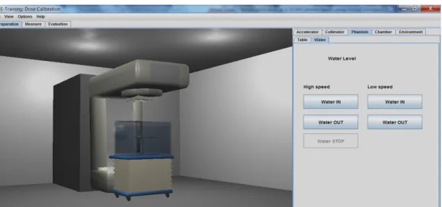
246. (Hartmann G. H., 2009). A GUI of this software is given in figure
1.
Figure 1- E-training Dose Calibration Program
As is described in user manual and in G. H. Hartmann (2009) publication, this program is
structured in three main parts: preparation of measurement, simulation of measurement,
calculation and evaluation of parameters. Based on these guidelines, first we set up the measuring
equipment.
3. Results and Discussions
To perform measurements with virtual simulator, we followed these steps:
-
Preparation of accelerator: we put up the gantry and collimator at zero; we selected the
type of radiation and energy 15 MeV and reference field size
10 x 10
.
-
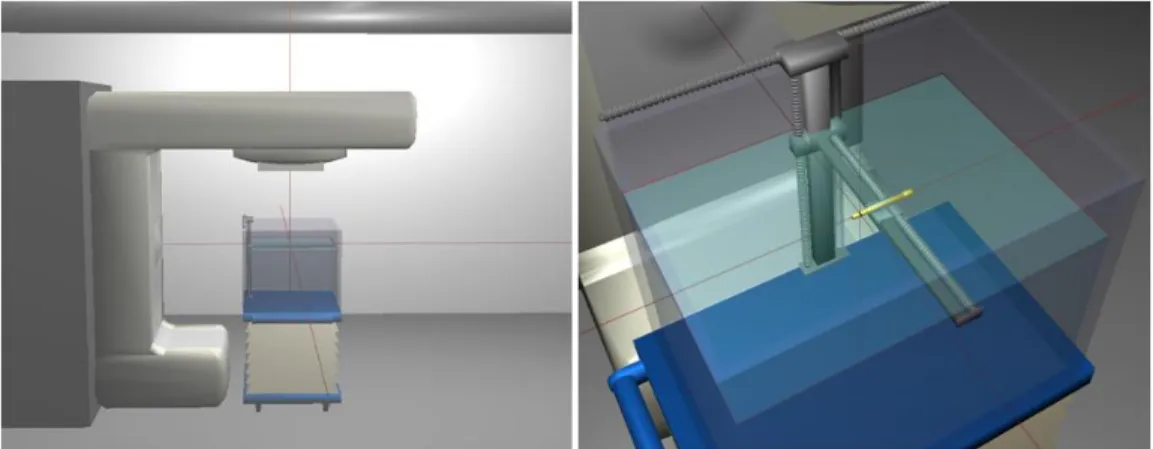
Preparation of water phantom: we filled the water phantom and adjust the SSD
(source-surface distance) according laser system reference, (figure 2. a). Also we measured virtual
temperature and air pressure.
246 We thank Dr. G. Hartmann EFOMP & German Cancer Research Center (DKFZ), for providing this program to Niko Hyka and Dafina Xhako, students of the “Training Course on Medical Physics for Radiation Therapy: Dosimetry and Treatment Planning for Basic and Advanced Applications”, organized at ICTP, Trieste Italy.
-
Chamber preparation: In our case we used cylindrical chamber, model 30013 Farmer, inner
radius of sensitive volume
r = 3.1 mm
. According PTW user manual calibration factor is
N =
5.233 Gy/C
and the voltage to be applied is 400 V. We adjusted to central ray the ionisation
chamber; we placed the chamber correctly to zero depth, and arrange the voltage and polarity.
(figure 2.b)
Figure 2 - Virtual simulator positioning of: a) linear accelerator and lasers, b) phantom and ionisation chamber
Table 1. Reference condition parameters. Reference conditions for 15 MeV photons:
Field size: 10 cm x 10 cm
SSD (source-surface distance) 99.98 cm
Measurement depth in water: 10 cm (for PDD, 0.5 - 25 cm) Positioning of chamber: central electrode at measuring depth Reference water temperature: T0=20°C
Reference air pressure: P0=101.325 kPa Measured water temperature (virtual simulation): T = 20.6 °C Measured air pressure (virtual simulation): P = 98.18 kPa
Measurement under reference conditions (IAEA, 2005):
To determine the absorbed dose at
z
max,
for a given beam, we use the central axis percentage depth dose (PDD) data for SSD set-ups and
tissue maximum ratios (TMR) for SAD set-ups. Clinical dosimetry requires the measurements of
central axis percentage depth dose (PDD) distributions, tissue phantom ratios (TPR) or tissue
maximum ratios (TMR), isodose distributions, transverse beam profiles and output factors as a
function of field size and shape for both reference and non-reference conditions (figure 3, a).
Such measurements should be made for all possible combinations of field size and SSD or SAD
used for radiotherapy treatment. An example of a depth dose measurement at central ray is shown
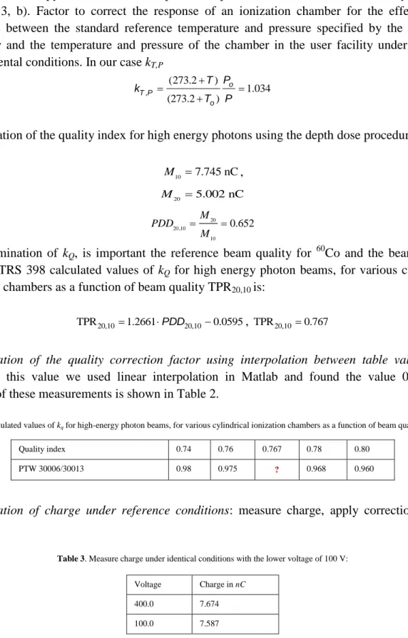
in figure 3, b). Factor to correct the response of an ionization chamber for the effect of the
difference between the standard reference temperature and pressure specified by the standards
laboratory and the temperature and pressure of the chamber in the user facility under different
environmental conditions. In our case
k
T,P, (273.2 ) 1.034 (273.2 ) o T P o P T k T P
Determination of the quality index for high energy photons using the depth dose procedure:
10 7.745 nC M
,
20 5.002 nC M 20 20,10 10 0.652 M PDD M For determination of
k
Q, is important the reference beam quality for
60Co and the beam quality
index
Q
. TRS 398 calculated values of
k
Qfor high energy photon beams, for various cylindrical
ionization chambers as a function of beam quality TPR
20,10is:
20,10 20,10
TPR 1.2661PDD 0.0595
,
TPR20,100.767Determination of the quality correction factor using interpolation between table values
. To
determine this value we used linear interpolation in Matlab and found the value 0.973. An
example of these measurements is shown in Table 2.
Table 2. Calculated values of kq for high-energy photon beams, for various cylindrical ionization chambers as a function of beam quality TPR20,10
Determination of charge under reference conditions
: measure charge, apply correction factors
(Table 3).
Table 3. Measure charge under identical conditions with the lower voltage of 100 V: Quality index 0.74 0.76 0.767 0.78 0.80
PTW 30006/30013 0.98 0.975 ? 0.968 0.960
Voltage Charge in nC
400.0 7.674
where reference saturation is 100% and used polarizing potential is 400 V positive. From
quadratic fit coefficients, for the calculation of k
sby the two voltage technique in pulsed and
pulsed–scanned radiation, as a function of the voltage ratio
V1/V2
, we found:
2 1 1 1 2 2 2 1.004
s o M M k a a a M M.
Used polarizing potential +400 V, the polarity effect for photon beams usually is very small. In
such a case where no information on the polarity used at calibration is given, it is better not to
perform any correction. It may be a wrong correction.
Determination of corrected charge,
:
Chamber reading in beam of quality
Q
corrected for
influence quantities to the reference conditions:
Q = 7.674 1.034 1.004 = 7.967 [nC/50 MU]
M
where:
k
s= 1.004 and
k
T,P=1.034.
Determination of
N
D,W,Qis based on calibration certificate of ionisation chamber. In our case we
used absorbed dose to water calibration factor
N
D,W,Q= 5.233 x 10⁷ Gy/C
for beam quality
60Co.
Using the formalism:
o o w,Q Q D,w,Q Q,Q D M N k
,
MQ 7.967 nC/50 MU,
o 7 w,Q D 5.233 x 10 Gy/C,
k o Q,Q 0.973,
we can calculate:
D w,15MV 0.812 Gy/100 MU